steering wheel adjustment FORD MUSTANG 1969 Volume One Chassis
[x] Cancel search | Manufacturer: FORD, Model Year: 1969, Model line: MUSTANG, Model: FORD MUSTANG 1969Pages: 413, PDF Size: 75.81 MB
Page 14 of 413
02-01-03
Brakes
02-01-03
vacuum system is operating, the pedal
will tend to fall away under foot pres-
sure and less pressure will be required
to hold the pedal in the applied posi-
tion. If no action is felt, the vacuum
booster system is not functioning.
If the brake pedal movement feels
spongy, bleed the hydraulic system to
remove air from the system. Refer to
Hydraulic System Bleeding, Part 1,
Section 2.
VACUUM TESTS—VACUUM
RELEASE PARKING BRAKES
Visually check the operation of the
brake linkage as the brake pedal is
depressed. Then, check the operation
of the brake linkage when the manual
release lever is activiated. These
checks should indicate whether the
manual parking brake control linkage
is operating properly or requires re-
pair or adjustment due to inability of
the parking brake to hold against
moderate vehicle movement. Perform
tests of the parking brake system and
controls after making certain the link-
age and manual controls operate
properly.
When testing a parking brake vacu-
um release system, a minimum of 10
inches of vacuum (Hg.) should be
available at all points where vacuum is
applied. This can be checked with a
Rotunda Fuel Pump Tester Gauge
(ARE345) and two Distributor Tester
hose adapters (Marked Q) connected
together with a coupling. This allows
the Fuel Pump Tester Gauge hose to
be adapted to any other vacuum hose
or rubber connector in the vacuum
systems.
Failure to maintain 10 inches of
vacuum (Hg.) during vacuum system
tests could be caused by a loose hose
connection, resulting in a vacuum
leak. When checking for vacuum be-
tween two points, trace the hose along
the entire routing to be sure it is not
crossed with another hose and con-
nected to the wrong connection.
All of the vacuum parking brake
control checks are to be performed
with the engine running at idle speed.
Leaks in the parking brake hoses or
a disconnected or improperly con-
nected hose can usually be found by
listening for a hissing sound along the
hose routings. Under no circumstances
should air pressure be applied to the
vacuum system as the actuator dia-
phragm in the parking brake vacuum
motor may be damaged.
1.
Start the engine and run it at
idle speed. With the transmission shift
control in neutral, depress the parking
brake pedal to apply the parking
brake. Move the transmission shift
control to D range and observe the
parking brake pedal to see that the
pedal moves upward and the parking
brake releases. If the parking brake
releases, the parking brake vacuum
control is working properly.
2.
If the parking brake does not re-
lease, test for vacuum at the steering
column neutral switch port in the
junction block, vacuum lines and the
parking brake release vacuum motor.
Use the Rotunda Vacuum and Fuel
Pump Tester 345. This can be accom-
plished by removing the hose from
each component and attaching it to
the vacuum gauge. Connect two dis-
tributor tester vacuum hose adapters
together with a coupling as a connec-
tor to attach the gauge. A minimum
of ten inches of vacuum is required to
actuate the parking brake vacuum
motor. Do not remove any of the vac-
uum hoses from the junction block
unless the junction block is being re-
placed, as the plastic nipples are thin
and very brittle and damage may re-
sult. If a minimum reading is not
present when checking each of the
aforementioned components, they
must be replaced.
ROAD TEST
A road test should be conducted
only when the operator is sure the
brakes will stop the vehicle.
If the road test reveals one or more
problem conditions, correct all mal-
functions of the vacuum system, brake
booster and hydraulic system prior to
removing brake drums, brake calipers,
brake shoes and linings or backing
plates.
ANTI-SKID CONTROL
SYSTEM TESTS
No adjustments or repairs are to be
performed on the skid control system.
Damaged or worn parts are to be re-
placed.
Refer to Ford Car and Truck Diag-
nosis Manual for Testing procedures.
COMMON ADJUSTMENTS AND REPAIRS
PARKING BRAKE LINKAGE
ADJUSTMENT
FORD, MERCURY, METEOR,
FAIRLANE, MONTEGO,
FALCON, MUSTANG
AND COUGAR
Check the parking brake cables
when the brakes are fully released. If1
the cables are loose, adjust them as
follows:
1.
Fully release the parking brake
pedal by pulling the release lever.
2.
Depress the parking brake pedal
until it is engaged in the first notch of
the control. On a vacuum release
brake, the first notch will be approxi-
mately two inches of pedal travel.
3.
Raise the vehicle. With the
transmission in neutral, turn the ad-
justing nut forward against the equal-
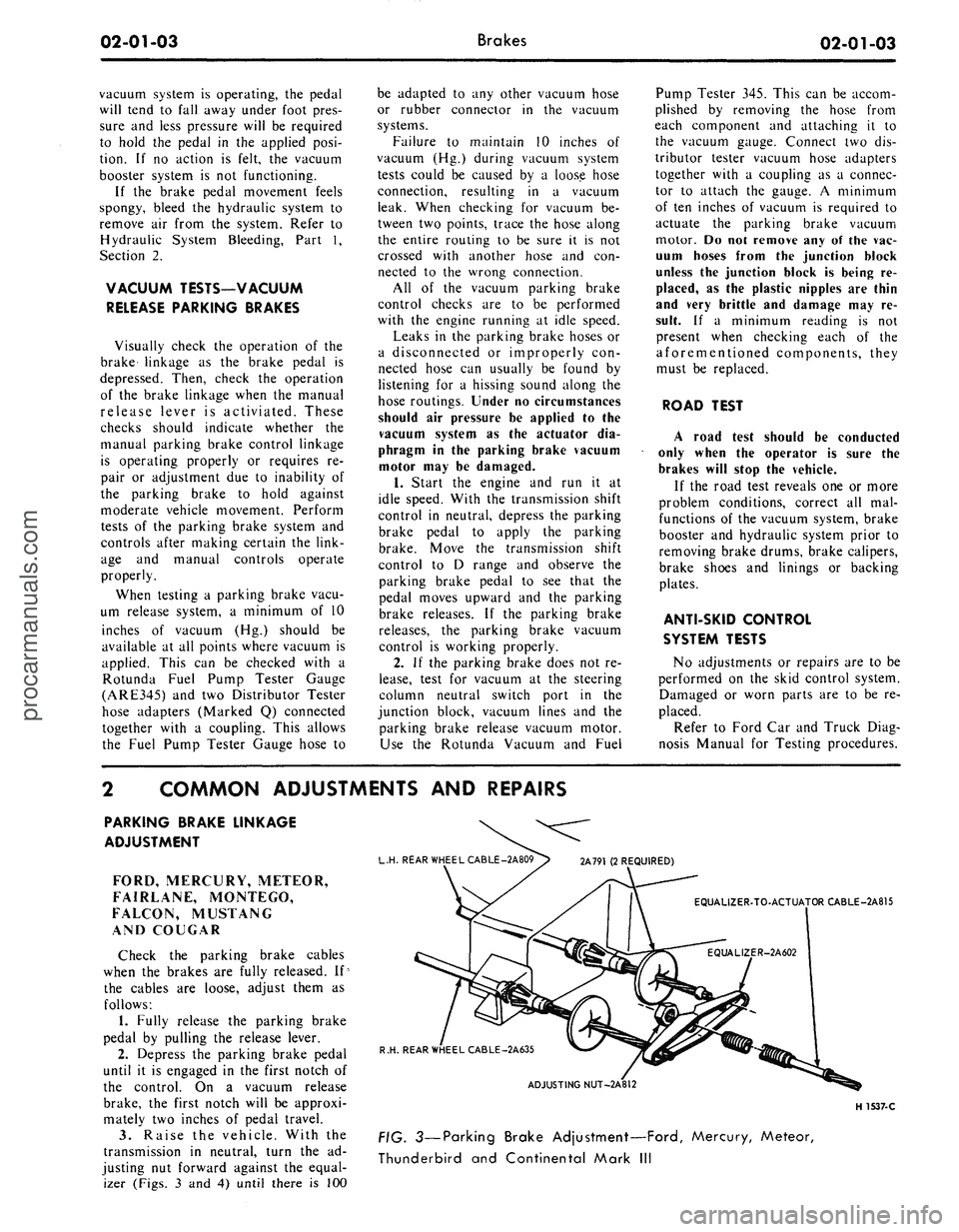
izer (Figs. 3 and 4) until there is 100
L.H. REAR WHEEL CABLE -2A809> 2A791 (2 REQUIRED)
EQUALIZER-TO-ACTUATOR CABLE-2A815
R.H. REAR WHEEL CABLE-2A635
ADJUSTING NUT-2A812
H 1537-C
FIG. 3—Parking Brake Adjustment—Ford, Mercury, Meteor,
Thunderbird and Continental Mark IIIprocarmanuals.com
Page 66 of 413
03-01-01
PART
3-1
PAGE
Suspension,
Steering, Wheels and
Tires,
General Service 03-01-01
PART
3-2
Suspension 03-02-01
PART
3-3
Automatic
Air
Leveling System ....03-03-01
PART
3-4
Automatic
Air
Leveling System
Lincoln Continental 03-04-01
PART
3-5
Steering Columns and Linkage ... 03-05-01
PART
3-6
Manual Steering 03-06-01
PART
3-7
Ford Design Non-Integral Power
Steering System
03-07-01
PART
3-8
PAGE
Ford Design Integral Power
Steering Gear 03-08-01
PART
3-9
Saginaw Design Integral Power
Steering Gear 03-09-01
PART
3-10
Ford-Thompson Power Steering
Pump 03-10-01
PART
3-11
Eaton Power Steering Pump 03-1
1-01
PART 3-12
Wheels and Tires 03-1 2-01
PART
3-13
Specifications
03-13-01
PART
3-1
Suspension,Steering, Wheels
and
Tires—General Service
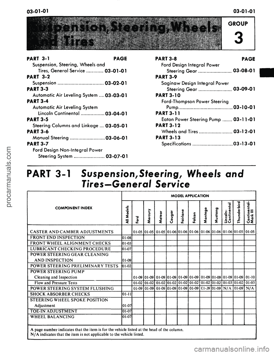
COMPONENT INDEX
CASTER AND CAMBER ADJUSTMENTS
FRONT
END
INSPECTION
FRONT WHEEL ALIGNMENT CHECKS
LUBRICANT CHECKING PROCEDURE
POWER STEERING GEAR CLEANING
AND INSPECTION
POWER STEERING PRELIMINARY TESTS
POWER STEERING PUMP
Cleaning
and
Inspection
Flow
and
Pressure Tests
POWER STEERING SYSTEM FLUSHING
SHOCK ABSORBER CHECKS
STEERING WHEEL SPOKE POSITION
Adjustment
TOE-IN ADJUSTMENT
WHEEL BALANCING
MODEL APPLICATION
All
Models
01-08
01-03
01-07
01-09
01-02
01-11
01-07
01-07
01-07
Ford
01-05
01-09
01-02
01-09
Mercury
01-05
01-09
01-02
01-09
Meteor
01-05
01-09
01-02
01-09
Cougar
01-06
01-09
01-02
01-09
Fairlane
01-06
01-09
01-02
01-09
Falcon
01-06
01-09
01-02
01-09
Montego
01-06
01-09
01-02
Gl-09
Mustang
01-06
01-09
01-02
01-09
Lincoln-
Continental
01-06
01-09
01-03
N/A
Thunderbird
01-05
01-09
01-02
01-09
Continental-
Mark
III
01-05
01-10
01-03
N/A
A page number indicates that
the
item
is for the
vehicle listed
at the
head
of the
column.
N/A indicates that
the
item
is not
applicable
to the
vehicle listed.
procarmanuals.com
Page 67 of 413
03-01-02
Suspension — Steering, Wheels And Tires — General Service
03-01-02
1 TESTING
POWER STEERING-
PRELIMINARY TESTS
The following preliminary checks
should always be made before per-
forming any operations.
AIR BLEEDING
Air in the power steering system
(shown by bubbles in the fluid) should
be bled. After making sure that the
reservoir is filled to specification (the
fluid must be at normal operating
temperature when the check is made),
turn the steering wheel through its full
travel three or four times. Do not hold
the wheels against their stops. Re-
check the fluid level.
CHECK FLUID LEVEL
Run the engine until the fluid is at
normal operating temperature. Then
turn the steering wheel all the way to
the left and right several times, and
shut off the engine.
Check the fluid level in the power
steering reservoir. The level must show
on the cross hatching between the bot-
tom of the dipstick and the full mark
(Fig. 1). If the level is low, add
enough automatic transmission fluid
C1AZ-19582-A to raise the level to
the F mark on the dipstick. Do not
overfill the reservoir.
CHECK PUMP BELT
If the pump belt is broken, glazed,
or worn, replace it with a new belt.
Use only the specified type of belt.
Refer to Part 3-13 for belt adjustment
procedure.
CHECK FOR FLUID
LEAKS
With the engine idling, turn the
steering wheel from stop to stop sever-
al times. Check all possible leakage
points. Tighten all loose fittings, and
replace any damaged lines or defective
seats.
CHECK TURNING EFFORT
With the front wheels properly al-
igned and tire pressures correct, check
the effort required to turn the steering
wheel.
G 1508- A
FIG.
1—Power
Steering Pump
Dipstick
1.
With the vehicle on dry concrete,
set the parking brakes.
2.
With the engine warmed up and
running at idle speed, turn the steering
wheel to the left and right several
times to warm the fluid.
3.
Attach a pull scale to the rim of
the steering wheel. Measure the pull
required to turn the wheel one com-
plete revolution in each direction. The
effort required to rotate the steering
wheel should not exceed specifications
given in Part 3-13.
POWER STEERING PUMP FLOW
AND PRESSURE TESTS—
EXCEPT LINCOLN CONTINENTAL
AND CONTINENTAL MARK III
The power steering flow and pres-
sure tests will show whether the pump,
steering gear or power assist control
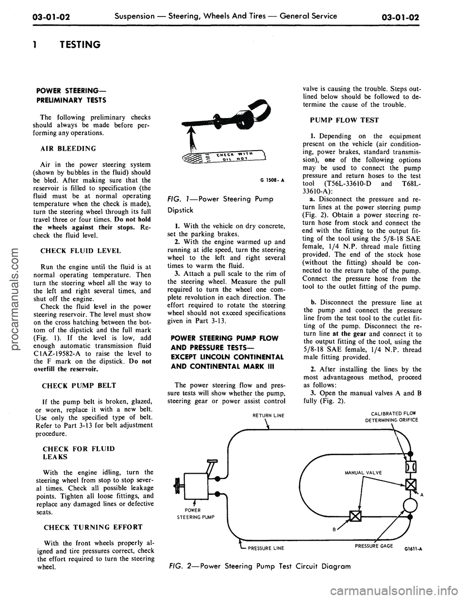
RETURN LINE
POWER
STEERING PUMP
Sr
valve is causing the trouble. Steps out-
lined below should be followed to de-
termine the cause of the trouble.
PUMP FLOW TEST
1.
Depending on the equipment
present on the vehicle (air condition-
ing, power brakes, standard transmis-
sion),
one of the following options
may be used to connect the pump
pressure and return hoses to the test
tool (T56L-3361O-D and T68L-
33610-A):
a. Disconnect the pressure and re-
turn lines at the power steering pump
(Fig. 2). Obtain a power steering re-
turn hose from stock and connect the
end with the fitting to the output fit-
ting of the tool using the
5/8-18
SAE
female, 1/4 N.P. thread male fitting
provided. The end of the stock hose
(without the fitting) should be con-
nected to the return tube of the pump.
Connect the pressure hose from the
tool to the outlet fitting of the pump.
b.
Disconnect the pressure line at
the pump and connect the pressure
line from the test tool to the outlet fit-
ting of the pump. Disconnect the re-
turn line at the gear and connect it to
the output fitting of the tool, using the
5/8-18
SAE female, 1/4 N.P. thread
male fitting provided.
2.
After installing the lines by the
most advantageous method, proceed
as follows:
3.
Open the manual valves A and B
fully (Fig. 2).
CALIBRATED FLOW
DETERMINING ORIFICE
PRESSURE LINE
FIG. 2—Power Steering Pump Test Circuit Diagram
PRESSURE GAGE
G1611-Aprocarmanuals.com
Page 68 of 413
03-01-03
Suspension — Steering, Wheels And Tires — General Service
03-01-03
4.
Connect a tachometer, start the
engine and operate it at idle speed
until the reservoir fluid temperature
reaches 165 to 175. This temperature
must be maintained throughout the
test. Valve B may be partially closed
to create a back pressure up to 350
psi to hasten the temperature rise. The
reservoir fluid must be at the proper
level.
5.
With the engine operating at rec-
ommended idle rpm and fluid temper-
ature noted in Step 4, close the manu-
al valve B. The minimum acceptable
pressure reading is 620 psi.
6. If the pressure gauge reading is
below the minimum specification, the
pump is at fault and should be re-
paired with necessary parts.
7.
If the reading is at or above the
minimum specification, the pump flow
is normal. Open manual valve B and
proceed to the Pump Fluid Pressure
Test.
PUMP FLUID
PRESSURE TEST
1.
Keep the lines and tools con-
nected as in the Pump Flow Test.
2.
With manual valves A and B
opened fully, operate the engine at
recommended idle speed (Fig. 2).
Close manual valve A, then manual
valve B. Do not keep both valves
closed for more than 5 seconds as this
would abnormally increase the fluid
temperature and cause undue pump
and/or gear wear.
3.
With the valves fully closed, the
pressure gauge should read 1000 psi
minimum for Ford, Mercury, Meteor
or Thunderbird and 750 psi minimum
for Cougar, Fairlane, Falcon, Monte-
go or Mustang.
4.
If the pressure gauge reading is
below the minimum specification, the
pump is at fault and should be re-
paired with necessary parts.
5.
If the pressure gauge reading is
at or above the minimum specifica-
tions,
the pump is normal and the
power steering gear or power assist
control valve is at fault.
FLUID PRESSURE TEST-
LINCOLN CONTINENTAL AND
CONTINENTAL MARK III
The pressure testing gauge set, tool
T56L-33610-D, requires modification
to make it adaptable for installation
in the power steering hydraulic sys-
tem. The parts required and the modi-
fication procedure are as follows:
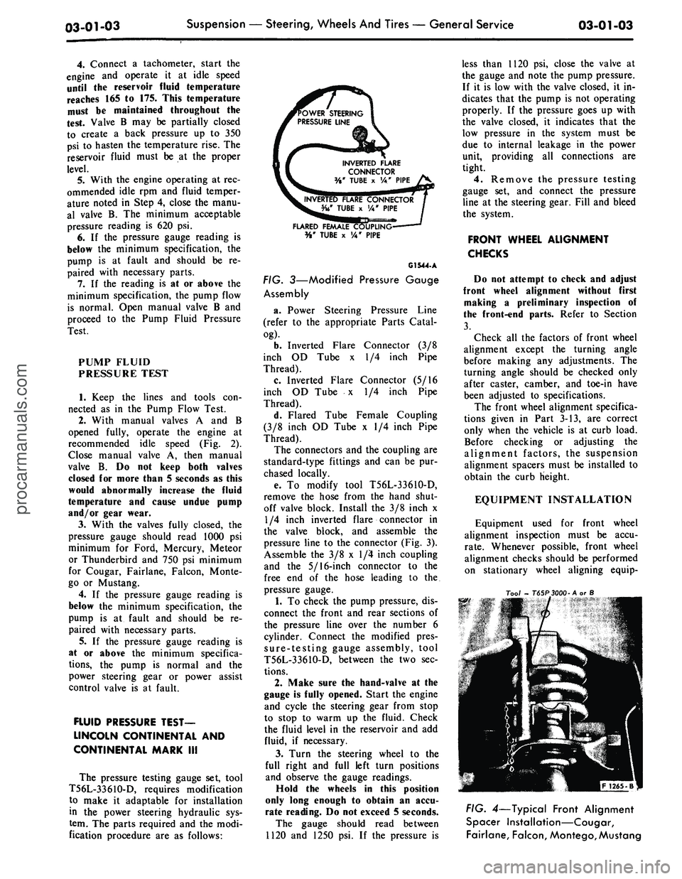
OWER STEERING
PRESSURE LINE
INVERTED FLARE
CONNECTOR
%* TUBE x VA" PIPE
FLARED FEMALE COUPW
%' TUBE x VA" PIPE
G1544.A
FIG. 3—Modified Pressure Gauge
Assembly
a. Power Steering Pressure Line
(refer to the appropriate Parts Catal-
og).
b.
Inverted Flare Connector (3/8
inch OD Tube x 1/4 inch Pipe
Thread).
c. Inverted Flare Connector (5/16
inch OD Tube x 1/4 inch Pipe
Thread).
d. Flared Tube Female Coupling
(3/8 inch OD Tube x 1/4 inch Pipe
Thread).
The connectors and the coupling are
standard-type fittings and can be pur-
chased locally.
e. To modify tool T56L-33610-D,
remove the hose from the hand shut-
off valve block. Install the 3/8 inch x
1/4 inch inverted flare connector in
the valve block, and assemble the
pressure line to the connector (Fig. 3).
Assemble the 3/8 x 1/4 inch coupling
and the 5/16-inch connector to the
free end of the hose leading to the.
pressure gauge.
1.
To check the pump pressure, dis-
connect the front and rear sections of
the pressure line over the number 6
cylinder. Connect the modified pres-
sure-testing gauge assembly, tool
T56L-3361O-D, between the two sec-
tions.
2.
Make sure the hand-valve at the
gauge is fully opened. Start the engine
and cycle the steering gear from stop
to stop to warm up the fluid. Check
the fluid level in the reservoir and add
fluid, if necessary.
3.
Turn the steering wheel to the
full right and full left turn positions
and observe the gauge readings.
Hold the wheels in this position
only long enough to obtain an accu-
rate reading. Do not exceed 5 seconds.
The gauge should read between
1120 and 1250 psi. If the pressure is
less than 1120 psi, close the valve at
the gauge and note the pump pressure.
If it is low with the valve closed, it in-
dicates that the pump is not operating
properly. If the pressure goes up with
the valve closed, it indicates that the
low pressure in the system must be
due to internal leakage in the power
unit, providing all connections are
tight.
4.
Remove the pressure testing
gauge set, and connect the pressure
line at the steering gear. Fill and bleed
the system.
FRONT WHEEL ALIGNMENT
CHECKS
Do not attempt to check and adjust
front wheel alignment without first
making a preliminary inspection of
the front-end parts. Refer to Section
3.
Check all the factors of front wheel
alignment except the turning angle
before making any adjustments. The
turning angle should be checked only
after caster, camber, and toe-in have
been adjusted to specifications.
The front wheel alignment specifica-
tions given in Part 3-13, are correct
only when the vehicle is at curb load.
Before checking or adjusting the
alignment factors, the suspension
alignment spacers must be installed to
obtain the curb Height.
EQUIPMENT INSTALLATION
Equipment used for front wheel
alignment inspection must be accu-
rate.
Whenever possible, front wheel
alignment checks should be performed
on stationary wheel aligning equip-
Too/
- T65P3000-A or S
FIG. 4—Typical Front Alignment
Spacer Installation—Cougar,
Fairlane, Falcon,
Montego,
Mustangprocarmanuals.com
Page 69 of 413
03-01-04
Suspension — Steering, Wheels And Tires — General Service
03-01-04
Tool
- T 65 P -
3000
B or C
1266-B
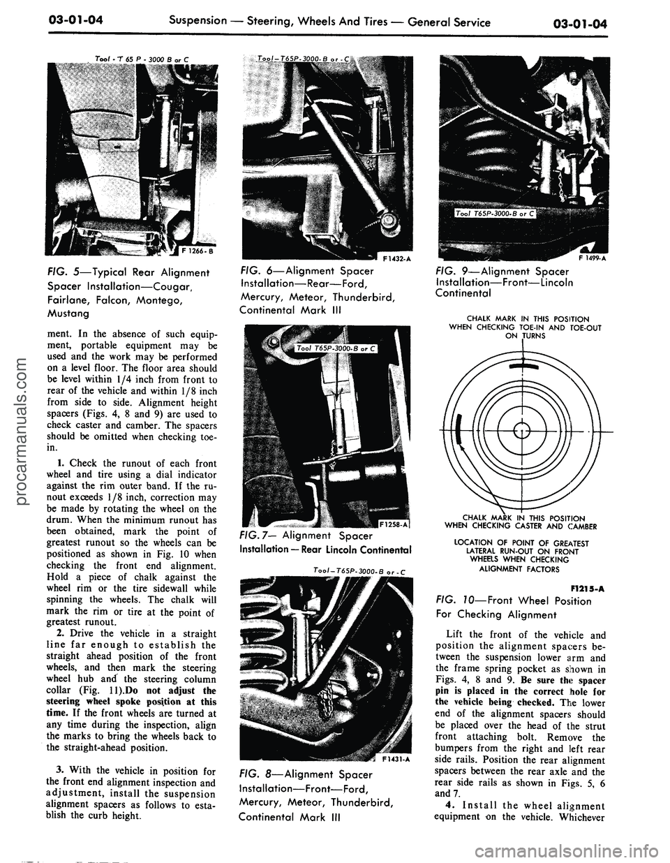
FIG. 5—Typical Rear Alignment
Spacer Installation—Cougar,
Fairlane, Falcon, Montego,
Mustang
ment. In the absence of such equip-
ment, portable equipment may be
used and the work may be performed
on a level floor. The floor area should
be level within 1/4 inch from front to
rear of the vehicle and within 1/8 inch
from side to side. Alignment height
spacers (Figs. 4, 8 and 9) are used to
check caster and camber. The spacers
should be omitted when checking toe-
in.
1.
Check the runout of each front
wheel and tire using a dial indicator
against the rim outer band. If the ru-
nout exceeds 1/8 inch, correction may
be made by rotating the wheel on the
drum. When the minimum runout has
been obtained, mark the point of
greatest runout so the wheels can be
positioned as shown in Fig. 10 when
checking the front end alignment.
Hold a piece of chalk against the
wheel rim or the tire sidewall while
spinning the wheels. The chalk will
mark the rim or tire at the point of
greatest runout.
2.
Drive the vehicle in a straight
line far enough to establish the
straight ahead position of the front
wheels, and then mark the steering
wheel hub and the steering column
collar (Fig. ll).Do not adjust the
steering wheel spoke position at this
time. If the front wheels are turned at
any time during the inspection, align
the marks to bring the wheels back to
the straight-ahead position.
3.
With the vehicle in position for
the front end alignment inspection and
adjustment, install the suspension
alignment spacers as follows to esta-
blish the curb height.
F1432-A
FIG. 6—Alignment Spacer
Installation—Rear—Ford,
Mercury, Meteor, Thunderbird,
Continental Mark III
|F1258-Af
FIG. 7— Alignment Spacer
Installation — Rear Lincoln Continental
Tool-T65P-3000-B or -C
F1431-A
FIG. 8—Alignment Spacer
Installation—Front—Ford,
Mercury, Meteor, Thunderbird,
Continental Mark III
F 1499-A
FIG. 9—Alignment Spacer
Installation—Front—Lincoln
Continental
CHALK MARK IN THIS POSITION
WHEN CHECKING TOE-IN AND TOE-OUT
ON TURNS
CHALK MARK IN THIS POSITION
WHEN CHECKING CASTER AND CAMBER
LOCATION OF POINT OF GREATEST
LATERAL RUN-OUT ON FRONT
WHEaS WHEN CHECKING
ALIGNMENT FACTORS
F1215-A
FIG. 70—Front Wheel Position
For Checking Alignment
Lift the front of the vehicle and
position the alignment spacers be-
tween the suspension lower arm and
the frame spring pocket as shown in
Figs.
4, 8 and 9. Be sure the spacer
pin is placed in the correct hole for
the vehicle being checked. The lower
end of the alignment spacers should
be placed over the head of the strut
front attaching bolt. Remove the
bumpers from the right and left rear
side rails. Position the rear alignment
spacers between the rear axle and the
rear side rails as shown in Figs. 5, 6
and 7.
4.
Install the wheel alignment
equipment on the vehicle. Whicheverprocarmanuals.com
Page 70 of 413
03-01-05
Suspension — Steering, Wheels And Tires — General Service
03-01-05
type of equipment is used, follow the
installation and inspection instructions
provided by the equipment manufactu-
rer.
CASTER
Check the caster angle at each front
wheel.
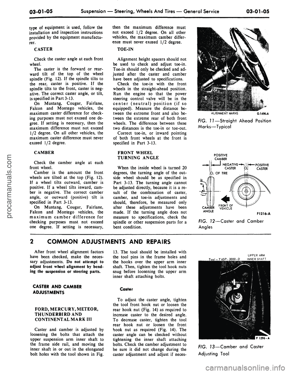
The caster is the forward or rear-
ward tilt of the top of the wheel
spindle (Fig. 12). If the spindle tilts to
the rear, caster is positive. If the
spindle tilts to the front, caster is neg-
ative. The correct caster angle, or tilt,
is specified in Part 3-13.
On Mustang, Cougar, Fairlane,
Falcon and Montego vehicles, the
maximum caster difference for check-
ing purposes must not exceed one de-
gree.
If setting is necessary, then the
maximum difference must not exceed
1/2 degree. On all other vehicles, the
maximum caster difference must never
exceed 1/2 degree.
CAMBER
Check the camber angle at each
front wheel.
Camber is the amount the front
wheels are tilted at the top (Fig. 12).
If a wheel tilts outward, camber is
positive. If a wheel tilts inward, cam-
ber is negative. The correct camber
angle, or outward (positive) tilt is
specified in Part 3-13.
On Mustang, Cougar, Fairlane,
Falcon and Montego vehicles, the
maximum camber difference for
checking purposes must not exceed
one degree. If setting is necessary,
then the maximum difference must
not exceed 1/2 degree. On all other
vehicles, the maximum camber differ-
ence must never exceed 1/2 degree.
TOE-IN
Alignment height spacers should not
be used to check and adjust toe-in.
Toe-in should only be checked and ad-
justed after the caster and camber
have been adjusted to specifications.
Check the toe-in with the front
wheels in the straight-ahead position.
Run the engine so that the power
steering control valve will be in the
center (neutral) position (if so
equipped). Measure the distance be-
tween the extreme front and also be-
tween the extreme rear of both front
wheels. The difference between these
two distances is the toe-in or toe-out.
Correct toe-in, or inward pointing
of both front wheels at the front is
specified in Part 3-13.
FRONT WHEEL
TURNING ANGLE
When the inside wheel is turned 20
degrees, the turning angle of the out-
side wheel should be as specified in
Part 3-13. The turning angle cannot
be adjusted directly, because it is a re-
sult of the combination of caster,
camber, and toe-in adjustments and
should, therefore, be measured only
after these adjustments have been
made. If the turning angle does not
measure to specifications, check the
spindle or other suspension parts for a
bent condition.
ALIGNMENT
MARKS
G-1496-A
FIG. I?—Straight Ahead Position
Marks—Typical
POSITIVE
CAMBER
• •
NEGATIVE-*!
| ^*—
CASTER
ICL
OF TIRE
POSITIVE
CASTER
5r\
CA&U
ANGlE
F1216-A
FIG. 72—Caster and Camber
Angles
COMMON ADJUSTMENTS AND REPAIRS
After front wheel alignment factors
have been checked, make the neces-
sary adjustments. Do not attempt to
adjust front wheel alignment by bend-
ing the suspension or steering parts.
CASTER AND CAMBER
ADJUSTMENTS
FORD, MERCURY, METEOR,
THUNDERBIRDAND
CONTINENTAL MARK III
Caster and camber is adjusted by
loosening the bolts that attach the
upper suspension arm inner shaft to
the frame side rail, and moving the
inner shaft in or out in the elongated
bolt holes with the tool shown in Fig.
13.
The tool should be installed with
the tool pins in the frame holes and
the hooks over the upper arm inner
shaft. Then, tighten the tool hook nuts
snug before loosening the upper arm
inner shaft attaching bolts.
Caster
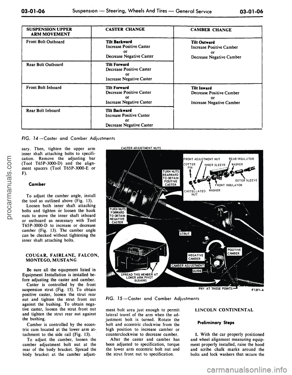
To adjust the caster angle, tighten
the tool front hook nut or loosen the
rear hook nut (Fig. 14) as required to
increase caster to the desired angle.
To decrease caster, tighten the tool
rear hook nut or loosen the front
hook nut as required (Fig. 14). The
caster angle can be checked without
tightening the inner shaft attaching
bolts.
Check the camber adjustment to
be sure it did not change during the
caster adjustment and adjust if neces-
FIG. 73—Camber and Caster
Adjusting Toolprocarmanuals.com
Page 71 of 413
03-01-06
Suspension — Steering, Wheels And Tires — General Service
03-01-06
SUSPENSION UPPER
ARM MOVEMENT
Front Bolt Outboard
Rear Bolt Outboard
Front Bolt Inboard
Rear Bolt Inboard
CASTER CHANGE
Tilt Backward
Increase Positive Caster
or
Decrease Negative Caster
Tilt Forward
Decrease Positive Caster
or
Increase Negative Caster
Tilt Forward
Decrease Positive Caster
or
Increase Negative Caster
Tilt Backward
Increase Positive Caster
or
Decrease Negative Caster
CAMBER CHANGE
Tilt Outward
Increase Positive Camber
or
Decrease Negative Camber
Tilt Inward
Decrease Positive Camber
or
Increase Negative Camber
FIG. 14—Caster and Camber Adjustments
sary. Then, tighten the upper arm
inner shaft attaching bolts to specifi-
cation. Remove the adjusting bar
(Tool T65P-3OOO-D) and the align-
ment spacers (Tool T65P-3O00-E or
F).
Camber
To adjust the camber angle, install
the tool as outlined above (Fig. 13).
Loosen both inner shaft attaching
bolts and tighten or loosen the hook
nuts to move the inner shaft inboard
or outboard as necessary with Tool
T65P-3OOO-D to increase or decrease
camber (Fig. 13). The camber angle
can be checked without tightening the
inner shaft attaching bolts.
COUGAR, FAIRLANE, FALCON,
MONTEGO, MUSTANG
Be sure all the equipment listed in
Equipment Installation is installed be-
fore adjusting the caster and camber.
Caster is controlled by the front
suspension strut (Fig. 15). To obtain
positive caster, loosen the strut rear
nut and tighten the strut front nut
against the bushing. To obtain nega-
tive caster, loosen the strut front nut
and tighten the strut rear nut against
the bushing.
Camber is controlled by the eccen-
tric cam located at the lower arm at-
tachment to the side rail (Fig. 13).
To adjust the camber, loosen the
camber adjustment bolt nut at the
rear of the body bracket. Spread the
body bracket at the camber adjust-
TER ADJUSTMENT NUTS
EAR INSULATOR
WASHER
FRONT ADJUSTMENT NUT
INNER SLEEVE
TURN NUTS
REARWARD
TO OBTAIN
POSITIVE
CASTER
OUTER SLEEVE
RONT INSULATOR
WASHER
CASTELLATED
NUT
TURN NUTS
FORWARD
TO OBTAIN
NEGATIVE
CASTER
NEGATIVE
CAMBER
SPREAD THIS MEMBER AT
LOWER ARM PIVOT
BUSHING
PRY AT THESE POINTS'
F1371-A
FIG. J5—Caster and Camber Adjustments
ment bolt area just enough to permit
lateral travel of the arm when the ad-
justment bolt is turned. Rotate the
bolt and eccentric clockwise from the
high position to increase camber or
counterclockwise to decrease camber.
After the caster and camber has
been adjusted to specification, torque
the lower arm eccentric bolt nut and
the strut front nut to specification.
LINCOLN CONTINENTAL
Preliminary Steps
1.
With the car properly positioned
and wheel alignment measuring equip-
ment properly installed, raise the hood
and scribe chalk marks around the
bolts and lock washers that secure theprocarmanuals.com
Page 72 of 413
03-01-07
Suspension — Steering, Wheels And Tires — General Service
03-01-07
upper arm shaft to the frame member
(Fig. 3, Part 3-2).
2.
Loosen the arm shaft attaching
bolts,
raise the front end of the vehicle
and lower it again. This will break the
arm shaft loose from the frame mem-
ber.
3.
With a pry bar, move the arm
shaft back into alignment with the
chalk marks made in Step 1, and
tighten the shaft attaching bolts. The
bolts should be tightened just enough
to hold the shaft in position without
preventing its being moved with the
pry bar.
Caster
1.
With the aid of a pry bar, move
the shaft in or out, as required, to
meet specifications. A movement of
approximately 3 /32 inch at either the
front or rear bolt location will change
the caster 1/2 degree. Inboard move-
ment of the front bolt, or outboard
movement of the rear bolt, will change
caster in the negative direction. Out-
board movement of the front bolt, or
inboard movement of the rear bolt,
will change caster in the positive di-
rection.
2.
When the caster is correct, tor-
que the shaft attaching bolts to speci-
fication and recheck the caster and
camber to insure that the readings
have not changed.
Camber
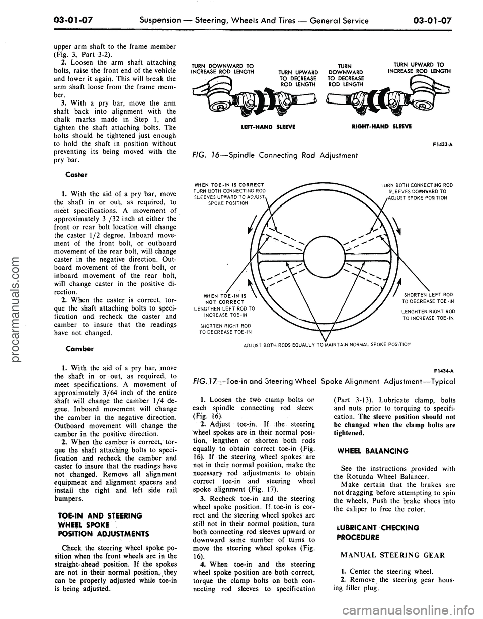
TURN DOWNWARD TO
INCREASE ROD LENGTH
TURN UPWARD
TO DECREASE
ROD LENGTH
TURN
DOWNWARD
TO DECREASE
ROD LENGTH
TURN UPWARD TO
INCREASE ROD LENGTH
LEFT-HAND SLEEVE
RIGHT-HAND SLEEVE
FIG. 16—Spindle Connecting Rod Adjustment
WHEN TOE-IN IS CORRECT
TURN BOTH CONNECTING ROD
SLEEVES UPWARD TO ADJUST
SPOKE POSITION
F1433-A
i URN BOTH CONNECTING ROD
SLEEVES DOWNWARD TO
ADJUST SPOKE POSITION
WHEN TOE-IN IS
NOT CORRECT
LENGTHEN LEFT ROD TO
INCREASE TOE-IN
SHORTEN RIGHT ROD
TO DECREASE TOE-IN
SHORTEN LEFT ROD
TO DECREASE TOE-IN
LENGHTEN RIGHT ROD
TO INCREASE TOE-IN
ADJUST BOTH RODS EQUALLY TO MAINTAIN NORMAL SPOKE POSITION
1.
With the aid of a pry bar, move
the shaft in or out, as required, to
meet specifications. A movement of
approximately 3/64 inch of the entire
shaft will change the camber 1/4 de-
gree.
Inboard movement will change
the camber in the negative direction.
Outboard movement will change the
camber in the positive direction.
2.
When the camber is correct, tor-
que the shaft attaching bolts to speci-
fication and recheck the camber and
caster to insure that the readings have
not changed. Remove all alignment
equipment and alignment spacers and
install the right and left side rail
bumpers.
TOE-IN AND STEERING
WHEEL SPOKE
POSITION ADJUSTMENTS
Check the steering wheel spoke po-
sition when the front wheels are in the
straight-ahead position. If the spokes
are not in their normal position, they
can be properly adjusted while toe-in
is being adjusted.
F1434-
A
f/G.77—Toe-in and Steering Wheel Spoke Alignment Adjustment—Typical
1.
Loosen the two ciamp bolts or
each spindle connecting rod sleeve
(Fig. 16).
2.
Adjust toe-in. If the steering
wheel spokes are in their normal posi-
tion, lengthen or shorten both rods
equally to obtain correct toe-in (Fig.
16).
If the steering wheel spokes are
not in their normal position, make the
necessary rod adjustments to obtain
correct toe-in and steering wheel
spoke alignment (Fig. 17).
3.
Recheck toe-in and the steering
wheel spoke position. If toe-in is cor-
rect and the steering wheel spokes are
still not in their normal position, turn
both connecting rod sleeves upward or
downward same number of turns to
move the steering wheel spokes (Fig.
16).
4.
When toe-in and the steering
wheel spoke position are both correct,
torque the clamp bolts on both con-
necting rod sleeves to specification
(Part 3-13). Lubricate clamp, bolts
and nuts prior to torquing to specifi-
cation. The sleeve position should not
be changed when the clamp bolts are
tightened.
WHEEL BALANCING
See the instructions provided with
the Rotunda Wheel Balancer.
Make certain that the brakes are
not dragging before attempting to spin
the wheels. Push the brake shoes into
the caliper to free the rotor.
LUBRICANT CHECKING
PROCEDURE
MANUAL STEERING GEAR
1.
Center the steering wheel.
2.
Remove the steering gear hous-
ing filler plug.procarmanuals.com
Page 84 of 413
03-02-08
Suspension
03-02-08
IN-VEHICLE ADJUSTMENTS AND REPAIRS
HOISTING INSTRUCTIONS
Damage to steering linkage compo-
nents and front suspension struts may
occur if care is not exercised when po-
sitioning the hoist adapters of 2 post
hoists prior to lifting the vehicle.
If a 2 post hoist is used to lift the
vehicle, place the adapters under the
lower arms or the No. 1 crossmember.
Do not allow the adapters to contact
the steering linkage. If the adapters
are placed under the crossmember, a
piece of wood (2 x 4 x 16 inches)
should be placed on the hoist channel
between the adapters. This will pre-
vent the adapters from damaging the
front suspension struts.
UPPER BALL JOINT
REPLACEMENT
FORD, MERCURY,
METEOR, THUNDERBIRD,
CONTINENTAL MARK III
1.
Raise the vehicle high enough to
provide working space, and place a
support under the lower arm. If a
chain hoist or a jack that has a nar-
row contact pad is to be used on the
bumper to raise the vehicle, distribute
the load along the bumper by using a
steel plate 3 or 4 inches long as a con-
tact pad to prevent damaging the
bumper.
2.
Remove the wheel and tire.
3.
Drill a
1/8-inch
hole through
each upper ball joint retaining rivet.
Using a large chisel, cut off the rivets.
4.
Remove the upper arm suspen-
sion bumper.
5.
Remove the cotter pin and nut
from the upper ball joint stud.
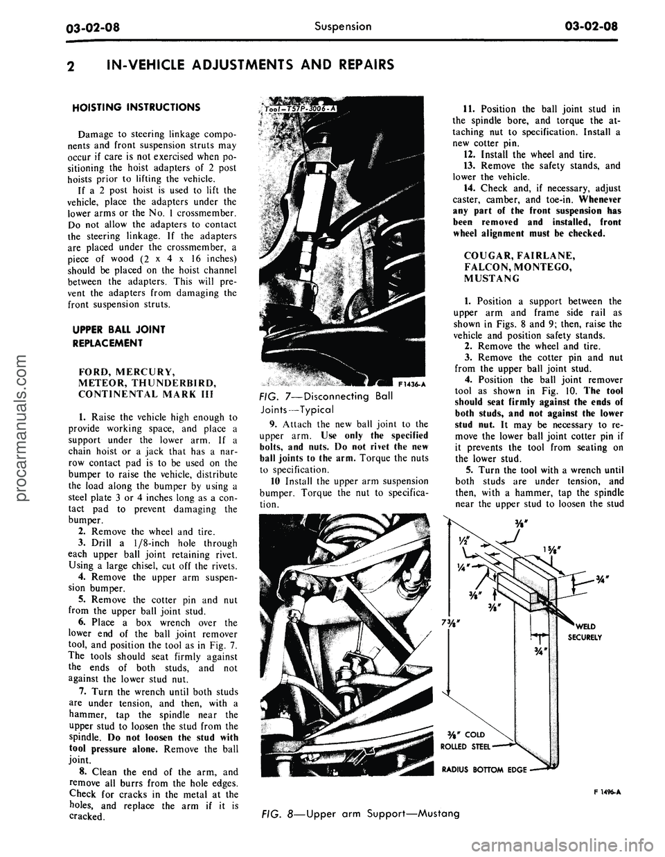
6. Place a box wrench over the
lower end of the ball joint remover
tool, and position the tool as in Fig. 7.
The tools should seat firmly against
the ends of both studs, and not
against the lower stud nut.
7.
Turn the wrench until both studs
are under tension, and then, with a
hammer, tap the spindle near the
upper stud to loosen the stud from the
spindle. Do not loosen the stud with
tool pressure alone. Remove the ball
joint.
8. Clean the end of the arm, and
remove all burrs from the hole edges.
Check for cracks in the metal at the
holes,
and replace the arm if it is
cracked.
F1436-A
FIG. 7—Disconnecting Ball
Joints—Typical
9. Attach the new ball joint to the
upper arm. Use only the specified
bolts,
and nuts. Do not rivet the new
ball joints to the arm. Torque the nuts
to specification.
10 Install the upper arm suspension
bumper. Torque the nut to specifica-
tion.
11.
Position the ball joint stud in
the spindle bore, and torque the at-
taching nut to specification. Install a
new cotter pin.
12.
Install the wheel and tire.
13.
Remove the safety stands, and
lower the vehicle.
14.
Check and, if necessary, adjust
caster, camber, and toe-in. Whenever
any part of the front suspension has
been removed and installed, front
wheel alignment must be checked.
COUGAR, FAIRLANE,
FALCON, MONTEGO,
MUSTANG
1.
Position a support between the
upper arm and frame side rail as
shown in Figs. 8 and 9; then, raise the
vehicle and position safety stands.
2.
Remove the wheel and tire.
3.
Remove the cotter pin and nut
from the upper ball joint stud.
4.
Position the ball joint remover
tool as shown in Fig. 10. The tool
should seat firmly against the ends of
both studs, and not against the lower
stud nut. It may be necessary to re-
move the lower ball joint cotter pin if
it prevents the tool from seating on
the lower stud.
5.
Turn the tool with a wrench until
both studs are under tension, and
then, with a hammer, tap the spindle
near the upper stud to loosen the stud
F 1496-A
FIG. 8—Upper arm Support—Mustangprocarmanuals.com
Page 95 of 413
03-02-19
Suspension
03-02-19
6. Raise the upper arm to free the
ball joint stud from the spindle. Wire
the upper end of the spindle to the un-
derbody to prevent damage to the
brake hose.
7.
Mark the position of the upper
arm shaft on the underbody member
to facilitate making caster and camber
adjustments after installation of the
upper arm.
8. Remove the suspension upper
arm-to-underbody attaching bolts,
lock washers, and attaching nuts.
Then, remove the upper arm.
Installation
1.
Position the upper arm shaft on
the underbody member. Line up the
shaft with the marks made before re-
moval of the arm.
2.
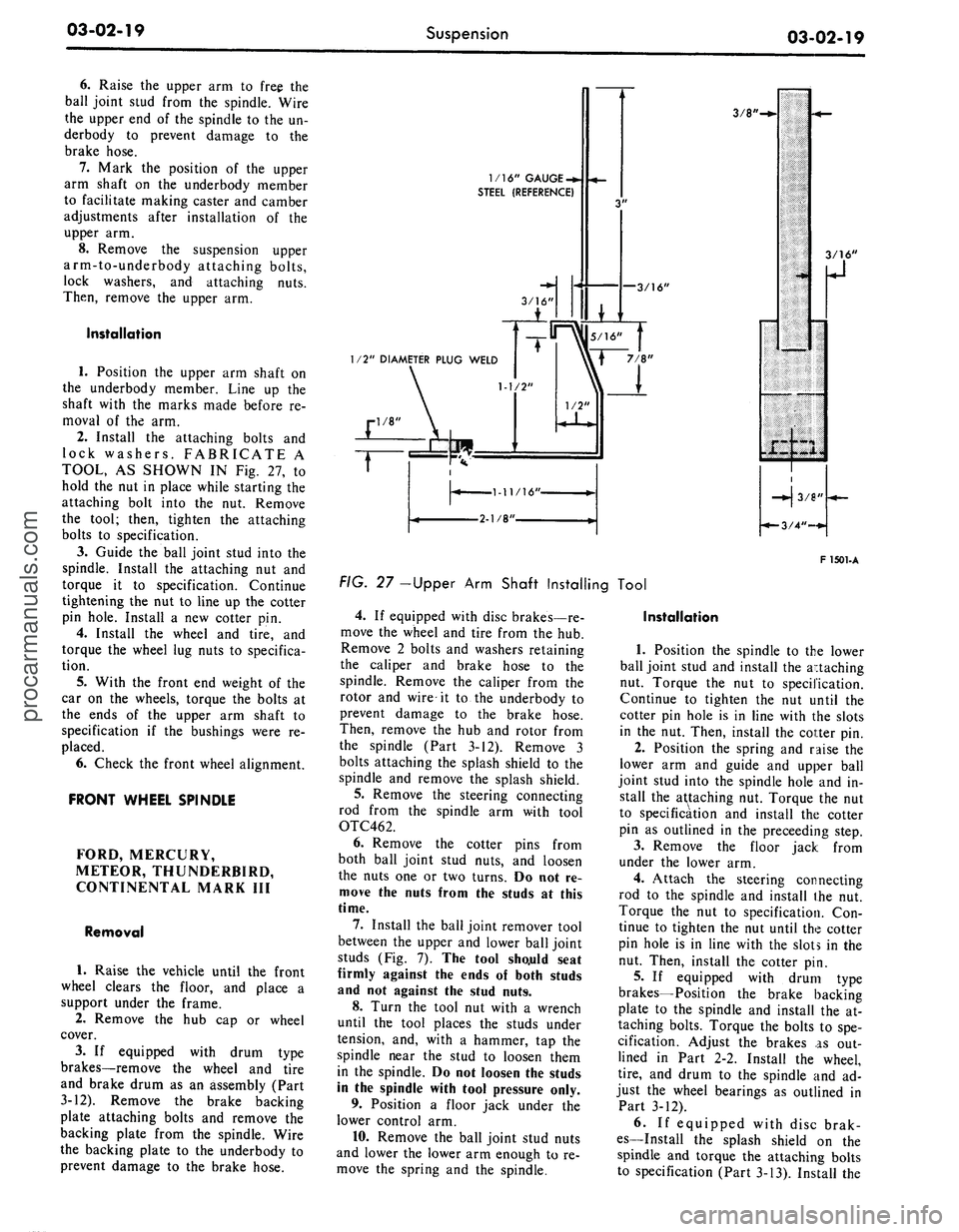
Install the attaching bolts and
lock washers. FABRICATE A
TOOL, AS SHOWN IN Fig. 27, to
hold the nut in place while starting the
attaching bolt into the nut. Remove
the tool; then, tighten the attaching
bolts to specification.
3.
Guide the ball joint stud into the
spindle. Install the attaching nut and
torque it to specification. Continue
tightening the nut to line up the cotter
pin hole. Install a new cotter pin.
4.
Install the wheel and tire, and
torque the wheel lug nuts to specifica-
tion.
5.
With the front end weight of the
car on the wheels, torque the bolts at
the ends of the upper arm shaft to
specification if the bushings were re-
placed.
6. Check the front wheel alignment.
FRONT WHEEL SPINDLE
FORD, MERCURY,
METEOR, THUNDERBIRD,
CONTINENTAL MARK III
Removal
1.
Raise the vehicle until the front
wheel clears the floor, and place a
support under the frame.
2.
Remove the hub cap or wheel
cover.
3.
If equipped with drum type
brakes—remove the wheel and tire
and brake drum as an assembly (Part
3-12). Remove the brake backing
plate attaching bolts and remove the
backing plate from the spindle. Wire
the backing plate to the underbody to
prevent damage to the brake hose.
1/16" GAUGE
-*.
STEEL (REFERENCE)
—3/16'
3/8'
1/2" DIAMETER PLUG WELD
F 1501-A
FIG. 27 -Upper Arm Shaft Installing Tool
4.
If equipped with disc brakes—re-
move the wheel and tire from the hub.
Remove 2 bolts and washers retaining
the caliper and brake hose to the
spindle. Remove the caliper from the
rotor and wire it to the underbody to
prevent damage to the brake hose.
Then, remove the hub and rotor from
the spindle (Part 3-12). Remove 3
bolts attaching the splash shield to the
spindle and remove the splash shield.
5.
Remove the steering connecting
rod from the spindle arm with tool
OTC462.
6. Remove the cotter pins from
both ball joint stud nuts, and loosen
the nuts one or two turns. Do not re-
move the nuts from the studs at this
time.
7.
Install the ball joint remover tool
between the upper and lower ball joint
studs (Fig. 7). The tool sho.uld seat
firmly against the ends of both studs
and not against the stud nuts.
8. Turn the tool nut with a wrench
until the tool places the studs under
tension, and, with a hammer, tap the
spindle near the stud to loosen them
in the spindle. Do not loosen the studs
in the spindle with tool pressure only.
9. Position a floor jack under the
lower control arm.
10.
Remove the ball joint stud nuts
and lower the lower arm enough to re-
move the spring and the spindle.
Installation
1.
Position the spindle to the lower
ball joint stud and install the attaching
nut. Torque the nut to specification.
Continue to tighten the nut until the
cotter pin hole is in line with the slots
in the nut. Then, install the cotter pin.
2.
Position the spring and raise the
lower arm and guide and upper ball
joint stud into the spindle hole and in-
stall the attaching nut. Torque the nut
to specification and install the cotter
pin as outlined in the preceeding step.
3.
Remove the floor jack from
under the lower arm.
4.
Attach the steering connecting
rod to the spindle and install the nut.
Torque the nut to specification. Con-
tinue to tighten the nut until the cotter
pin hole is in line with the slots in the
nut. Then, install the cotter pin.
5.
If equipped with drum type
brakes—Position the brake backing
plate to the spindle and install the at-
taching bolts. Torque the bolts to spe-
cification. Adjust the brakes as out-
lined in Part 2-2. Install the wheel,
tire,
and drum to the spindle and ad-
just the wheel bearings as outlined in
Part 3-12).
6. If equipped with disc brak-
es—Install the splash shield on the
spindle and torque the attaching bolts
to specification (Part 3-13). Install theprocarmanuals.com