stop start FORD MUSTANG 1969 Volume One Chassis
[x] Cancel search | Manufacturer: FORD, Model Year: 1969, Model line: MUSTANG, Model: FORD MUSTANG 1969Pages: 413, PDF Size: 75.81 MB
Page 13 of 413
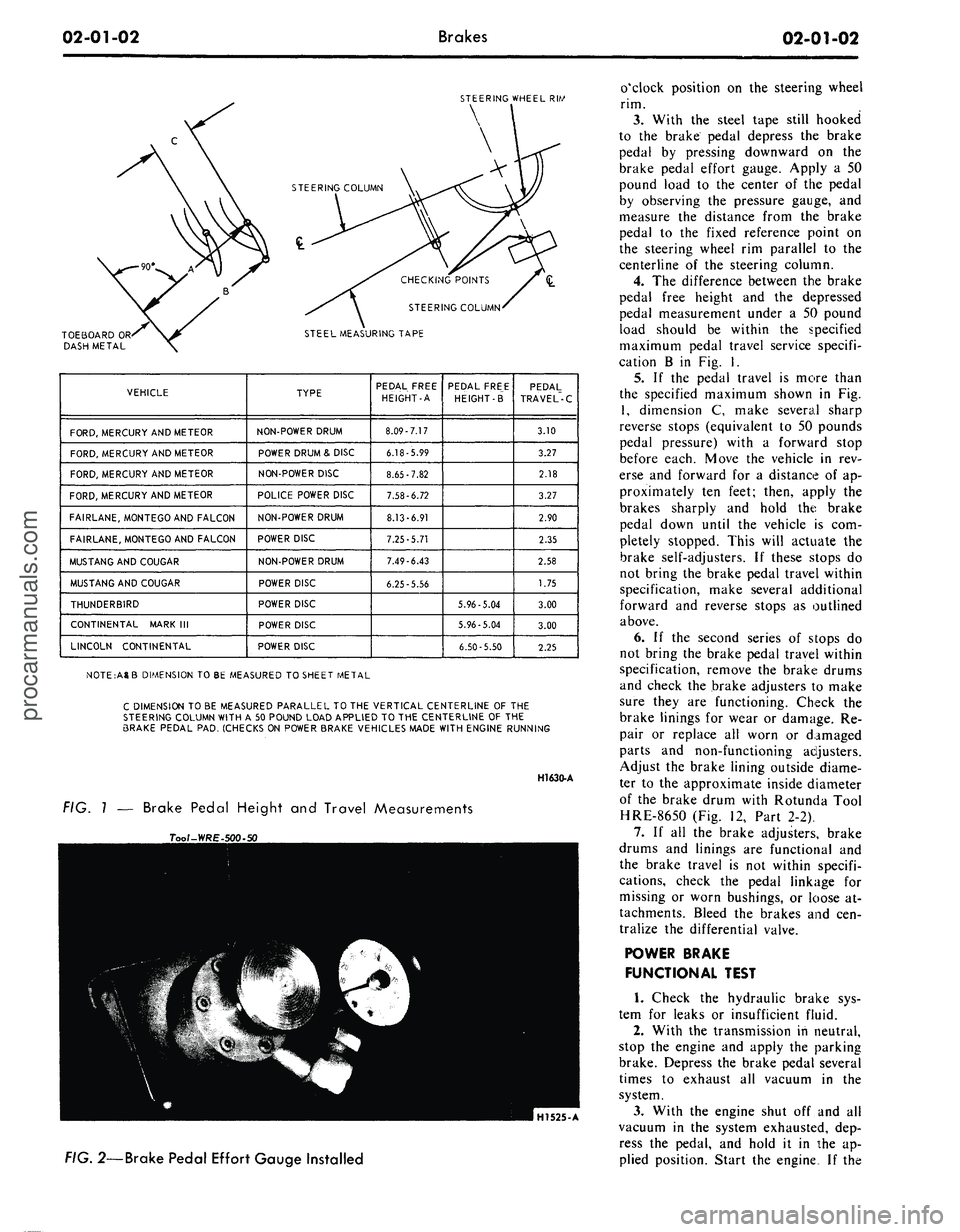
02-01-02
Brakes
02*01-02
STEERING
WHEEL RIW
TOEBOARD
OR
DASH
METAL
CHECKING
POINTS
STEERING
COLUMN-
STEEL
MEASURING TAPE
VEHICLE
FORD,
MERCURY AND METEOR
FORD,
MERCURY AND METEOR
FORD,
MERCURY AND METEOR
FORD,
MERCURY AND METEOR
FAIRLANE,
MONTEGO AND FALCON
FAIRLANE,
MONTEGO AND FALCON
MUSTANG
AND COUGAR
MUSTANG
AND COUGAR
THUNDERBIRD
CONTINENTAL
MARK III
LINCOLN
CONTINENTAL
TYPE
NON-POWER
DRUM
POWER
DRUM & DISC
NON-POWER
DISC
POLICE
POWER DISC
NON-POWER
DRUM
POWER
DISC
NON-POWER
DRUM
POWER
DISC
POWER
DISC
POWER
DISC
POWER
DISC
PEDAL
FREE
HEIGHT-A
8.09-7.17
6.18-5.99
8.65-7.82
7.58-6.72
8.13-6.91
7.25-5.71
7.49-6.43
6.25-5.56
PEDAL
FREE
HEIGHT-B"
5.96-5.04
5.96-5.04
6.50-5.50
PEDAL
TRAVEL-C
3.10
3.27
2.18
3.27
2.90
2.35
2.58
1.75
3.00
3.00
2.25
NOTE:AgB
DIMENSION TO BE MEASURED TO SHEET METAL
C
DIMENSION TO BE MEASURED PARALLEL TO THE VERTICAL CENTERLINE OF THE
STEERING
COLUMN WITH A 50 POUND LOAD APPLIED TO THE CENTERLINE OF THE
BRAKE
PEDAL PAD. (CHECKS ON POWER BRAKE VEHICLES MADE WITH ENGINE RUNNING
H1630-A
FIG. 1 — Brake Pedal Height and Travel Measurements
Tool-WRE-l
HI525-A
FIG.
2—Brake Pedal Effort Gauge Installed
o'clock position on the steering wheel
rim.
3.
With the steel tape still hooked
to the brake pedal depress the brake
pedal by pressing downward on the
brake pedal effort gauge. Apply a 50
pound load to the center of the pedal
by observing the pressure gauge, and
measure the distance from the brake
pedal to the fixed reference point on
the steering wheel rim parallel to the
centerline of the steering column.
4.
The difference between the brake
pedal free height and the depressed
pedal measurement under a 50 pound
load should be within the specified
maximum pedal travel service specifi-
cation B in Fig. I.
5.
If the pedal travel is more than
the specified maximum shown in Fig.
1,
dimension C, make several sharp
reverse stops (equivalent to 50 pounds
pedal pressure) with a forward stop
before each. Move the vehicle in rev-
erse and forward for a distance of ap-
proximately ten feet; then, apply the
brakes sharply and hold the brake
pedal down until the vehicle is com-
pletely stopped. This will actuate the
brake self-adjusters. If these stops do
not bring the brake pedal travel within
specification, make several additional
forward and reverse stops as outlined
above.
6. If the second series of stops do
not bring the brake pedal travel within
specification, remove the brake drums
and check the brake adjusters to make
sure they are functioning. Check the
brake linings for wear or damage. Re-
pair or replace all worn or damaged
parts and non-functioning adjusters.
Adjust the brake lining outside diame-
ter to the approximate inside diameter
of the brake drum with Rotunda Tool
HRE-8650 (Fig. 12, Part 2-2).
7.
If all the brake adjusters, brake
drums and linings are functional and
the brake travel is not within specifi-
cations, check the pedal linkage for
missing or worn bushings, or loose at-
tachments. Bleed the brakes and cen-
tralize the differential valve.
POWER BRAKE
FUNCTIONAL TEST
1.
Check the hydraulic brake sys-
tem for leaks or insufficient fluid.
2.
With the transmission in neutral,
stop the engine and apply the parking
brake. Depress the brake pedal several
times to exhaust all vacuum in the
system.
3.
With the engine shut off and all
vacuum in the system exhausted, dep-
ress the pedal, and hold it in the ap-
plied position. Start the engine If theprocarmanuals.com
Page 14 of 413
02-01-03
Brakes
02-01-03
vacuum system is operating, the pedal
will tend to fall away under foot pres-
sure and less pressure will be required
to hold the pedal in the applied posi-
tion. If no action is felt, the vacuum
booster system is not functioning.
If the brake pedal movement feels
spongy, bleed the hydraulic system to
remove air from the system. Refer to
Hydraulic System Bleeding, Part 1,
Section 2.
VACUUM TESTS—VACUUM
RELEASE PARKING BRAKES
Visually check the operation of the
brake linkage as the brake pedal is
depressed. Then, check the operation
of the brake linkage when the manual
release lever is activiated. These
checks should indicate whether the
manual parking brake control linkage
is operating properly or requires re-
pair or adjustment due to inability of
the parking brake to hold against
moderate vehicle movement. Perform
tests of the parking brake system and
controls after making certain the link-
age and manual controls operate
properly.
When testing a parking brake vacu-
um release system, a minimum of 10
inches of vacuum (Hg.) should be
available at all points where vacuum is
applied. This can be checked with a
Rotunda Fuel Pump Tester Gauge
(ARE345) and two Distributor Tester
hose adapters (Marked Q) connected
together with a coupling. This allows
the Fuel Pump Tester Gauge hose to
be adapted to any other vacuum hose
or rubber connector in the vacuum
systems.
Failure to maintain 10 inches of
vacuum (Hg.) during vacuum system
tests could be caused by a loose hose
connection, resulting in a vacuum
leak. When checking for vacuum be-
tween two points, trace the hose along
the entire routing to be sure it is not
crossed with another hose and con-
nected to the wrong connection.
All of the vacuum parking brake
control checks are to be performed
with the engine running at idle speed.
Leaks in the parking brake hoses or
a disconnected or improperly con-
nected hose can usually be found by
listening for a hissing sound along the
hose routings. Under no circumstances
should air pressure be applied to the
vacuum system as the actuator dia-
phragm in the parking brake vacuum
motor may be damaged.
1.
Start the engine and run it at
idle speed. With the transmission shift
control in neutral, depress the parking
brake pedal to apply the parking
brake. Move the transmission shift
control to D range and observe the
parking brake pedal to see that the
pedal moves upward and the parking
brake releases. If the parking brake
releases, the parking brake vacuum
control is working properly.
2.
If the parking brake does not re-
lease, test for vacuum at the steering
column neutral switch port in the
junction block, vacuum lines and the
parking brake release vacuum motor.
Use the Rotunda Vacuum and Fuel
Pump Tester 345. This can be accom-
plished by removing the hose from
each component and attaching it to
the vacuum gauge. Connect two dis-
tributor tester vacuum hose adapters
together with a coupling as a connec-
tor to attach the gauge. A minimum
of ten inches of vacuum is required to
actuate the parking brake vacuum
motor. Do not remove any of the vac-
uum hoses from the junction block
unless the junction block is being re-
placed, as the plastic nipples are thin
and very brittle and damage may re-
sult. If a minimum reading is not
present when checking each of the
aforementioned components, they
must be replaced.
ROAD TEST
A road test should be conducted
only when the operator is sure the
brakes will stop the vehicle.
If the road test reveals one or more
problem conditions, correct all mal-
functions of the vacuum system, brake
booster and hydraulic system prior to
removing brake drums, brake calipers,
brake shoes and linings or backing
plates.
ANTI-SKID CONTROL
SYSTEM TESTS
No adjustments or repairs are to be
performed on the skid control system.
Damaged or worn parts are to be re-
placed.
Refer to Ford Car and Truck Diag-
nosis Manual for Testing procedures.
COMMON ADJUSTMENTS AND REPAIRS
PARKING BRAKE LINKAGE
ADJUSTMENT
FORD, MERCURY, METEOR,
FAIRLANE, MONTEGO,
FALCON, MUSTANG
AND COUGAR
Check the parking brake cables
when the brakes are fully released. If1
the cables are loose, adjust them as
follows:
1.
Fully release the parking brake
pedal by pulling the release lever.
2.
Depress the parking brake pedal
until it is engaged in the first notch of
the control. On a vacuum release
brake, the first notch will be approxi-
mately two inches of pedal travel.
3.
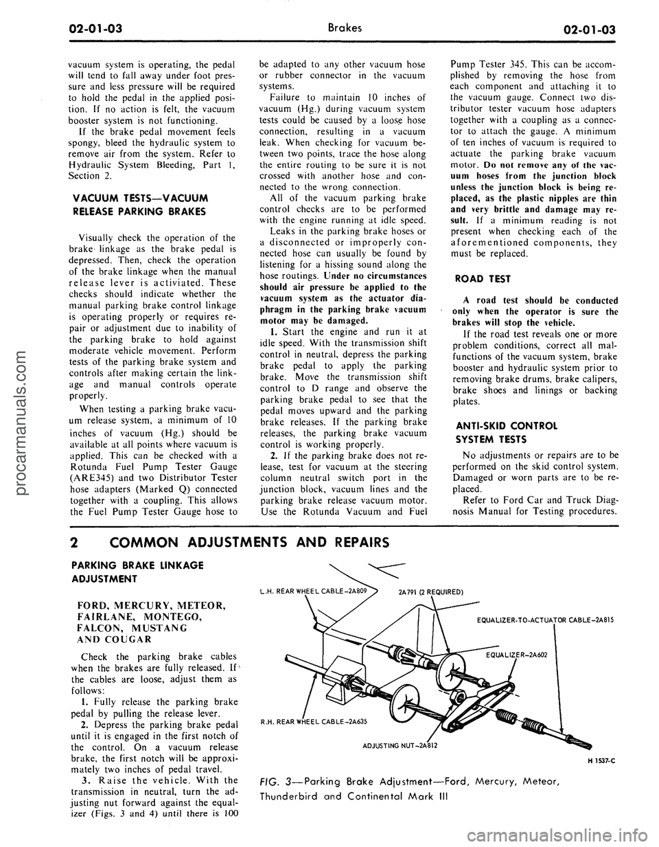
Raise the vehicle. With the
transmission in neutral, turn the ad-
justing nut forward against the equal-
izer (Figs. 3 and 4) until there is 100
L.H. REAR WHEEL CABLE -2A809> 2A791 (2 REQUIRED)
EQUALIZER-TO-ACTUATOR CABLE-2A815
R.H. REAR WHEEL CABLE-2A635
ADJUSTING NUT-2A812
H 1537-C
FIG. 3—Parking Brake Adjustment—Ford, Mercury, Meteor,
Thunderbird and Continental Mark IIIprocarmanuals.com
Page 17 of 413
02-01-06
Brakes
02-01-06
side.
Refill the master cylinder reser-
voir after each wheel cylinder is bled
and install the master cylinder cover
and gasket. Be sure the diaphragm
type gasket is properly positioned in
the master cylinder cover. When the
bleeding operation is completed, the
fluid level should be filled to within
1/4 inch of the top of the reservoirs.
7. If the primary (front brake) sys-
tem is to be bled. Repeat steps 2
through 6 at the right front brake cal-
iper or cylinder and ending at the left
front brake caliper or cylinder.
8. On disc brake equipped models
be sure that the front brake pistons
are returned to their normal positions
and that the shoe and lining assem-
blies are properly seated by depressing
the brake pedal several times until
normal pedal travel is established.
9. Centralize the pressure differen-
tial valve. Refer to the Centralizing
the Pressure Differential Valve proce-
dures which follow.
PRESSURE BLEEDING
The Lincoln Continental hydraulic
brake system is to be bled only with
pressure bleeding equipment.
Bleed the longest lines first. The
bleeder tank should contain enough
new Ford Brake Fluid to complete the
bleeding operation. Use Ford Brake
Fluid — Extra Heavy Duty — Part
Number C6AZ-19542-A (ESA-
M6C25-A) or equivalent for all brake
applications. The brake fluid is col-
ored blue for identification purposes.
Do not mix low temperature brake
fluid with the specified brake fluid
during the bleeding operations. Never
re-use brake fluid that has been
drained from the hydraulic system.
The tank should be charged with ap-
proximately 10 to 30 pounds of air
pressure. Never exceed 50 pounds
pressure.
1.
Clean all dirt from the master
cylinder reservoir cover.
2.
Remove the master cylinder res-
ervoir cover and rubber gasket, and
fill the master cylinder reservoir with
the specified brake fluid. Install the
pressure bleeder adapter tool to the
master cylinder, and attach the bleed-
er tank hose to the fittng on the
adapter.
Master cylinder pressure bleeder
adapter tools can be obtained from
the various manufacturers of pressure
bleeding equipment. Follow the in-
structions of the manufacturer when
installing the adapter.
3.
If the master cylinder is
equipped with a bleed screw, loosen
the bleed screw and bleed the master
cylinder until the fluid is free of air
bubbles; then, tighten the bleed screw.
Do not use the secondary piston stop
screw, located on the bottom of the
master cylinder, to bleed the master
cylinder.
4.
If the rear wheel cylinders, the
secondary brake system, are to be
bled, position a 3/8 inch box wrench
(Fig. 9) on the bleeder fitting on the
right rear brake wheel cylinder. At-
tach a bleeder tube to the bleeder fit-
ting. The end of the tube should fit
snugly around the bleeder fitting.
5. Open the valve on the bleeder
tank to admit pressurized brake fluid
to the master cylinder reservoir.
6. Submerge the free end of the
tube in a container partially filled with
clean brake fluid, and loosen the
bleeder fitting.
7.
When air bubbles cease to ap-
pear in the fluid at the submerged end
of the bleeder tube, close the bleeder
fitting and remove the tube.
8. Repeat steps 3 through 7 at the
left rear wheel cylinder.
9. If the vehicle is equipped with
disc brakes, repeat steps 4 through 7,
starting at the right front disc caliper
and ending at the left front disc cali-
per.
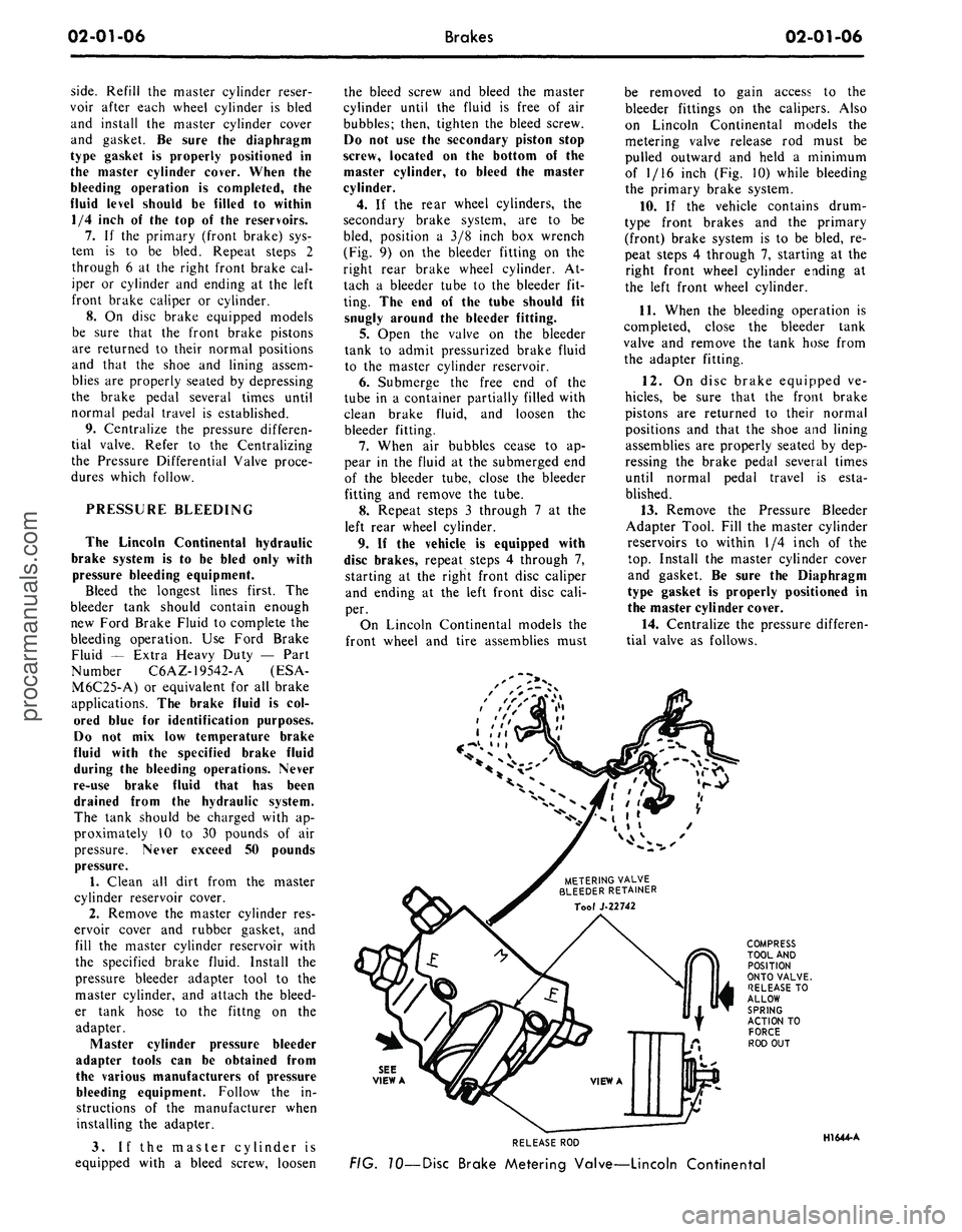
On Lincoln Continental models the
front wheel and tire assemblies must
be removed to gain access to the
bleeder fittings on the calipers. Also
on Lincoln Continental models the
metering valve release rod must be
pulled outward and held a minimum
of 1/16 inch (Fig. 10) while bleeding
the primary brake system.
10.
If the vehicle contains drum-
type front brakes and the primary
(front) brake system is to be bled, re-
peat steps 4 through 7, starting at the
right front wheel cylinder ending at
the left front wheel cylinder.
11.
When the bleeding operation is
completed, close the bleeder tank
valve and remove the tank hose from
the adapter fitting.
12.
On disc brake equipped ve-
hicles,
be sure that the front brake
pistons are returned to their normal
positions and that the shoe and lining
assemblies are properly seated by dep-
ressing the brake pedal several times
until normal pedal travel is esta-
blished.
13.
Remove the Pressure Bleeder
Adapter Tool. Fill the master cylinder
reservoirs to within 1/4 inch of the
top.
Install the master cylinder cover
and gasket. Be sure the Diaphragm
type gasket is properly positioned in
the master cylinder cover.
14.
Centralize the pressure differen-
tial valve as follows.
METERING VALVE
BLEEDER RETAINER
SEE
VIEW A
RELEASE ROD
FIG. 10—Disc Brake Metering Valve—Lincoln Continental
HI 644-Aprocarmanuals.com
Page 35 of 413
02-02-16
Brake System
02-02-16
fitting that connects the tube to the
cylinder. Do not pull the metal tube
away from the cylinder. Pulling the
tube out of the cylinder connection
will bend the metal tube and make in-
stallation difficult. The tube will sepa-
rate from the cylinder when the cylin-
der is removed from the backing
plate.
4.
On all except the front wheels on
Ford, Mercury, and Meteor models,
remove the wheel cylinder attaching
bolts and lock washers and remove the
cylinder. On the front wheel of Ford,
Mercury and Meteor models, remove
the nut and washer that attaches the
cylinder to the anchor pin. Remove
the cylinder from the anchor pin.
INSTALLATION
Wipe the end(s) of the hydraulic
line to remove any foreign matter be-
fore making connections.
1.
On all models except Ford, Mer-
cury and Meteor, to install a front
wheel cylinder, position the cylinder to
the backing plate. Install the two lock
washers and attaching bolts. Torque
them to specifications.
On Ford, Mercury and Meteor
models, to install a front wheel cylin-
der, position the cylinder on the an-
chor pin against the backing plate. In-
stall the washer and cylinder attaching
nut on the anchor pin, and torque it
to specification. Lock the washer re-
tainer securely.
2.
Install a new copper gasket over
the hose fitting. Thread the hose into
the cylinder and tighten it to specified
torque.
3.
Engage the opposite end of the
hose to the bracket on the frame. In-
stall the horseshoe-type retaining clip,
and connect the brake tube to the
hose with the tube fitting nut. Tighten
the nut to specification with tool
1112-144.
4.
To install a rear wheel cylinder,
place the rear wheel cylinder into po-
sition. Enter the tubing into the cylin-
der, and start the tube fitting nut into
the threads of the cylinder.
5.
Secure the cylinder to the back-
ing plate by installing the attaching
bolts and lock washers.
6. Tighten the tube fitting nut to
specification with tool 1112-144.
7.
Install the links in the ends of
the wheel cylinder, install the shoes
and adjuster assemblies, and adjust
the shoes as outlined in this section.
8. Adjust the brakes (Part 2-2, Sec-
tion 2). Install the brake drum and
wheel. Bleed the brakes and centralize
the differential valve as outlined in
Part 2-1, Section 2.
BRAKE BACKING PLATE
DRUM BRAKE
REMOVAL
1.
Remove the wheel and brake
drum. Disconnect the brake line from
the brake cylinder.
2.
Remove the brake shoe and ad-
juster assemblies and the wheel cylin-
der as outlined in this section. On the
rear wheels, disconnect the parking
brake lever from the cable.
3.
If the rear backing plate is being
replaced, remove the axle shaft from
the applicable rear axle as outlined in
Group 4, Part 4-2— Rear Axle, Sec-
tion 2, disengage parking brake cable
retainer from backing plate. Remove
the backing plate and gasket.
If the front backing plate is being
replaced, remove the bolts and nuts
that secure the backing plate to the
front wheel spindle and remove the
plate and gasket.
INSTALLATION
If a rear backing plate is to be re-
placed, position a new rear backing
plate and gasket on the attaching
bolts in the axle housing flange. Insert
parking brake cable into backing plate
and secure retaining fingers. Install
the rear axle shaft for applicable rear
axle.
Refer to Group 4, Part 4-2 —
Rear Axle, Section 2 for the proper
installation procedure.
1.
If the front brake backing plate
is to be replaced, position a new front
backing plate and gasket to the wheel
spindle and install the attaching bolts
and nuts.
2.
Install the wheel cylinder and
connect the brake line as outlined in
this section.
3.
Install the brake shoe and ad-
juster assemblies as outlined in this
section. On a rear brake, connect the
parking brake cable to the lever.
4.
Adjust the brake shoes (Section
2),
and install the brake drums and
wheels. Bleed the brake system and
centralize the differential valve as out-
lined in Part 2-1, Section 2.
DISC BRAKE CALIPER
ASSEMBLY
ALL MODELS EXCEPT
LINCOLN CONTINENTAL
Removal
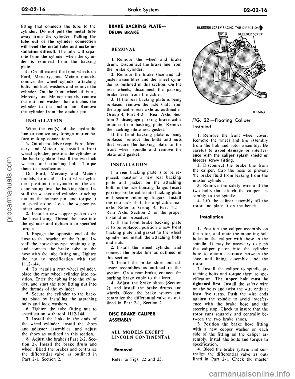
Refer to Figs. 22 and 23.
BLEEDER SCREW FACING THIS DIRECTION^
BLEEDER SCREW
H 1641-A
FIG. 22—Floating Caliper
Installed
1.
Remove the front wheel cover.
Remove the wheel and tire assembly
from the hub and rotor assembly. Be
careful to avoid damage or interfer-
ence with the caliper splash shield or
bleeder screw fitting.
2.
Disconnect the brake line from
the caliper. Cap the hose to prevent
*he brake fluid from leaking from the
master cylinder.
3.
Remove the safety wire and the
two bolts that attach the caliper as-
sembly to the spindle.
4.
Lift the caliper assembly off the
rotor and place it on the bench.
Installation
1.
Position the caliper assembly on
the rotor, and mate the mounting bolt
holes in the caliper with those in the
spindle. It may be necessary to push
the caliper piston into the cylinder
bore to obtain clearance between the
shoe and lining assembly and the
rotor.
2.
Install the caliper to spindle at-
taching bolts and torque them to spe-
cification. The upper bolt must be
tightened first. Install the safety wire
on the bolts and twist the wire ends at
least five turns. Push the wire ends
against the spindle to avoid interfer-
ence with the brake hose and the
steering stop. Check to insure that the
rotor runs squarely and centrally be-
tween the two brake shoes.
3.
Position the brake hose fitting
with a new copper washer on each
side of the fitting on the caliper as-
sembly. Install the bolts and torque to
specification.
4.
Bleed the brake system and cen-
tralize the differential valve as out-
lined in Part 2-1. Check the masterprocarmanuals.com
Page 58 of 413
02-02-39
Brake System
02-02-39
MAJOR REPAIR OPERATIONS
BRAKE DRUM REFINISHING
Minor scores on a brake drum can
be removed with sandpaper. A drum
that is excessively scored or shows a
total indicator runout of over 0.007
inch should be turned down. Remove
only enough stock to eliminate the
scores and true up the drum. The refi-
nished diameter must not exceed 0.060
inch oversize.
Check the inside diameter of the
brake drum with a brake drum mi-
crometer (Tool FRE-14^1).
If the drum diameter is less than
0.030 inch oversize after refinishing^
standard lining may be installed. If
the drum diameter is 0.030—0.060
inch oversize after refinishing, oversize
lining must be installed.
After a drum is turned down, wipe
the refinished surface with a cloth
soaked in clean denatured alcohol. If
one drum is turned down, the opposite
drum on the same axle should also be
cut down to the same size.
ROTOR REFINISHING
Rotunda Disc Brake Attachment,
FRE-2249-2, is the only recommended
tool to refinish the disc brake rotors.
The step-by-step resurfacing procedure
provided with the tool must be ad-
hered to.
The finished braking surfaces of the
rotor must be flat and parallel within
0.0007 inch; lateral runout must not
exceed 0.003 inch total indicator read-
ing, and the surface finish of the brak-
ing surfaces are to be 80/15 micro
inches. The minimum limiting dimen-
sions (Figs. 11 and 12, Part 2-1) from
the inboard bearing cup to the out-
board rotor face and from the inboard
bearing cup to the inboard rotor face
must be observed when removing ma-
terial from the rotor braking surfaces.
On all models except Lincoln Con-
tinental, the limiting dimensions are to
be measured with a ball and gage bar
(Rotunda Kit FRE-70160).
BRAKE SHOE RELINING
Brake linings that are worn to with-
in 1/32 inch of the rivet head or are
less than 0.030 inch thick (bonded lin-
ing) or have been contaminated with
brake fluid, grease or oil must be re-
placed. Failure to replace worn linings
will result in a scored drum. When it
is necessary to replace linings, they
must also be replaced on the wheel on
the opposite side of the vehicle.
Inspect brake shoes for distortion,
cracks, or looseness. If this condition
exists,
the shoe must be discarded. Do
not attempt to repair a defective brake
shoe.
1.
Wash the brake shoes thoroughly
in a clean solvent. Remove all burrs
or rough spots from the shoes.
2.
Check the inside diameter of the
brake drum with a brake drum mi-
crometer (tool FRE-1431). If the di-
ameter is less than 0.030 inches over-
size,
standard lining may be installed.
If the diameter is 0.030—0.060 inches
oversize, oversize lining should be in-
stalled.
3.
Position the new lining on the
shoe.
Starting in the center, insert and
secure the rivets, working alternately
towards each end. Replacement lin-
ings are ground and no further grind-
ing is required.
4.
Check the clearance between the
shoe and lining. The lining must seat
tightly against the shoe with not more
than 0.008 inch clearance between any
two rivets.
RETAINER - 2B245
DUAL MASTER CYLINDER
DISASSEMBLY
1.
Clean the outside of the master
cylinder and remove the filler cover
and diaphragm. Pour out any brake
fluid that remains in the cylinder. Dis-
card the old brake fluid.
2.*
Remove the secondary piston
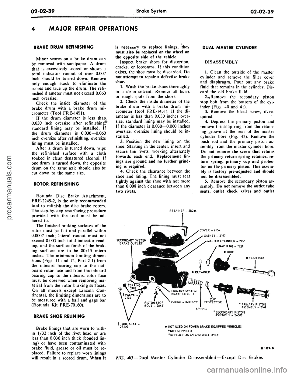
stop bolt from the bottom of the cyl-
inder (Figs. 40 and 41).
3.
Remove the bleed screw, iL re-
quired.
4.
Depress the primary piston and
remove the snap ring from the retain-
ing groove at the rear of the master
cylinder bore (Fig. 42). Remove the
push rod and the primary piston as-
sembly from the master cylinder bore.
Do not remove the screw that retains
the primary return spring retainer, re-
turn spring, primary cup and protec-
tor on the primary piston. This assem-
bly is factory pre-adjusted and should
not be disassembled.
5.
Remove the secondary piston as-
sembly. Do not remove the outlet tube
seats,
outlet check valves and outlet
SECONDARY SYSTEM
BRAKE OUTLET
COVER -2166
GASKET-2167
MASTER CYLINDER -2155
SNAP RING -7821
BOOT
PUSH ROD
PRIMARY PISTON
ASSEMBLY - 2169
tTUBE SEAT-
2B220
* SECONDARY PISTON
ASSEMBLY - 2A502
• NOT USED ON POWER BRAKE EQUIPPED VEHICLES
fNOT SERVICED
•REPLACE AS AN ASSEMBLY ONLY
H 1499-B
FIG. 40— Dual Master Cylinder Disassembled—Except Disc Brakesprocarmanuals.com
Page 68 of 413
03-01-03
Suspension — Steering, Wheels And Tires — General Service
03-01-03
4.
Connect a tachometer, start the
engine and operate it at idle speed
until the reservoir fluid temperature
reaches 165 to 175. This temperature
must be maintained throughout the
test. Valve B may be partially closed
to create a back pressure up to 350
psi to hasten the temperature rise. The
reservoir fluid must be at the proper
level.
5.
With the engine operating at rec-
ommended idle rpm and fluid temper-
ature noted in Step 4, close the manu-
al valve B. The minimum acceptable
pressure reading is 620 psi.
6. If the pressure gauge reading is
below the minimum specification, the
pump is at fault and should be re-
paired with necessary parts.
7.
If the reading is at or above the
minimum specification, the pump flow
is normal. Open manual valve B and
proceed to the Pump Fluid Pressure
Test.
PUMP FLUID
PRESSURE TEST
1.
Keep the lines and tools con-
nected as in the Pump Flow Test.
2.
With manual valves A and B
opened fully, operate the engine at
recommended idle speed (Fig. 2).
Close manual valve A, then manual
valve B. Do not keep both valves
closed for more than 5 seconds as this
would abnormally increase the fluid
temperature and cause undue pump
and/or gear wear.
3.
With the valves fully closed, the
pressure gauge should read 1000 psi
minimum for Ford, Mercury, Meteor
or Thunderbird and 750 psi minimum
for Cougar, Fairlane, Falcon, Monte-
go or Mustang.
4.
If the pressure gauge reading is
below the minimum specification, the
pump is at fault and should be re-
paired with necessary parts.
5.
If the pressure gauge reading is
at or above the minimum specifica-
tions,
the pump is normal and the
power steering gear or power assist
control valve is at fault.
FLUID PRESSURE TEST-
LINCOLN CONTINENTAL AND
CONTINENTAL MARK III
The pressure testing gauge set, tool
T56L-33610-D, requires modification
to make it adaptable for installation
in the power steering hydraulic sys-
tem. The parts required and the modi-
fication procedure are as follows:
OWER STEERING
PRESSURE LINE
INVERTED FLARE
CONNECTOR
%* TUBE x VA" PIPE
FLARED FEMALE COUPW
%' TUBE x VA" PIPE
G1544.A
FIG. 3—Modified Pressure Gauge
Assembly
a. Power Steering Pressure Line
(refer to the appropriate Parts Catal-
og).
b.
Inverted Flare Connector (3/8
inch OD Tube x 1/4 inch Pipe
Thread).
c. Inverted Flare Connector (5/16
inch OD Tube x 1/4 inch Pipe
Thread).
d. Flared Tube Female Coupling
(3/8 inch OD Tube x 1/4 inch Pipe
Thread).
The connectors and the coupling are
standard-type fittings and can be pur-
chased locally.
e. To modify tool T56L-33610-D,
remove the hose from the hand shut-
off valve block. Install the 3/8 inch x
1/4 inch inverted flare connector in
the valve block, and assemble the
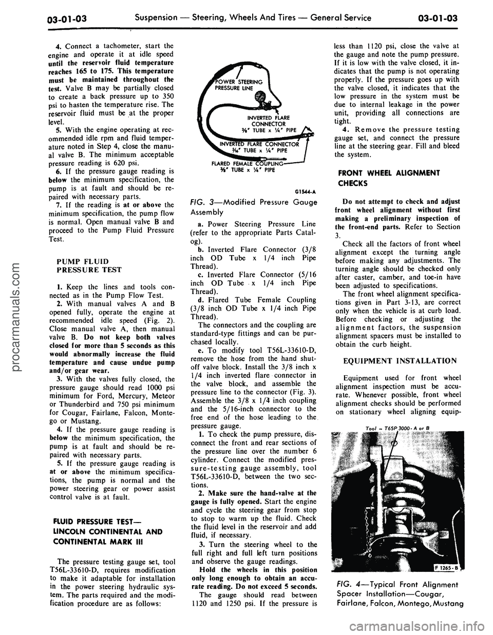
pressure line to the connector (Fig. 3).
Assemble the 3/8 x 1/4 inch coupling
and the 5/16-inch connector to the
free end of the hose leading to the.
pressure gauge.
1.
To check the pump pressure, dis-
connect the front and rear sections of
the pressure line over the number 6
cylinder. Connect the modified pres-
sure-testing gauge assembly, tool
T56L-3361O-D, between the two sec-
tions.
2.
Make sure the hand-valve at the
gauge is fully opened. Start the engine
and cycle the steering gear from stop
to stop to warm up the fluid. Check
the fluid level in the reservoir and add
fluid, if necessary.
3.
Turn the steering wheel to the
full right and full left turn positions
and observe the gauge readings.
Hold the wheels in this position
only long enough to obtain an accu-
rate reading. Do not exceed 5 seconds.
The gauge should read between
1120 and 1250 psi. If the pressure is
less than 1120 psi, close the valve at
the gauge and note the pump pressure.
If it is low with the valve closed, it in-
dicates that the pump is not operating
properly. If the pressure goes up with
the valve closed, it indicates that the
low pressure in the system must be
due to internal leakage in the power
unit, providing all connections are
tight.
4.
Remove the pressure testing
gauge set, and connect the pressure
line at the steering gear. Fill and bleed
the system.
FRONT WHEEL ALIGNMENT
CHECKS
Do not attempt to check and adjust
front wheel alignment without first
making a preliminary inspection of
the front-end parts. Refer to Section
3.
Check all the factors of front wheel
alignment except the turning angle
before making any adjustments. The
turning angle should be checked only
after caster, camber, and toe-in have
been adjusted to specifications.
The front wheel alignment specifica-
tions given in Part 3-13, are correct
only when the vehicle is at curb load.
Before checking or adjusting the
alignment factors, the suspension
alignment spacers must be installed to
obtain the curb Height.
EQUIPMENT INSTALLATION
Equipment used for front wheel
alignment inspection must be accu-
rate.
Whenever possible, front wheel
alignment checks should be performed
on stationary wheel aligning equip-
Too/
- T65P3000-A or S
FIG. 4—Typical Front Alignment
Spacer Installation—Cougar,
Fairlane, Falcon,
Montego,
Mustangprocarmanuals.com
Page 74 of 413
03-01-09
Suspension — Steering, Wheels And Tires — General Service
03-01-09
the reading exceeds specifications
(Part 3-13), replace the upper ball
joint.
LOWER BALL JOINT
INSPECTION
Ford,
Mercury, Meteor,
Thunderbird, Lincoln Continental
and Continental Mark III
1.
Raise the vehicle and place
jacks under the lower arms as shown
in Fig. 12. This will unload the lower
ball joints.
2.
Adjust the wheel bearings as des-
cribed in Part 3-12.
3.
Attach a dial indicator to the
lower arm and position the indicator
so that the plunger rests against the
inner side of the wheel rim adjacent to
the lower ball joint.
4.
Grasp the tire at the top and
bottom and slowly move the tire in
and out (Fig. 19). Note the reading
(radial play) on the dial indicator. If
the reading exceeds specifications
(Part 3-13), replace the lower ball
joint.
Cougar, Fairlane, Falcon,
Montego, Mustang
1.
Raise the vehicle on a frame
contact hoist or by floor jacks placed
beneath the underbody until the wheel
falls to the full down position.
2.
Ask an assistant to grasp the
lower edge of the tire and move the
wheel in and out.
3.
As the wheel is being moved in
and out, observe the lower end of the
spindle and the lower arm.
4.
Any movement between the
lower end of the spindle and the lower
arm indicates ball joint wear and loss
of preload. If any such movement is
observed, replace the lower arm.
During the foregoing check, the
upper ball joint will be unloaded and
may move. Disregard all such move-
ment of the upper ball joint. Also, do
not mistake loose wheel bearings for a
worn ball joint.
POWER STEERING GEAR
CLEANING
Disassembly and assembly of the
steering gear and. the sub-assemblies
must be made on a clean workbench.
As in repairing any hydraulically op-
erated unit, cleanliness is of utmost
importance. The bench, tools, and
parts must be kept clean at all times.
Thoroughly clean the exterior of the
unit with a suitable solvent and, when
necessary drain as much of the hy-
draulic fluid as possible. Handle all
parts very carefully to avoid nicks,
burrs,
scratches and dirt, which could
make the parts unfit for use.
Do not clean, wash or soak seals in
cleaning solvent.
INSPECTION
1.
Check the sector shaft contact
surface in the cover for wear. If worn,
replace the cover.
2.
Inspect the input shaft bearing
for cracked races and the balls for
looseness, wear, pitting, end play or
other damage. Check the fit of the
bearing on the input shaft. Replace
the bearing, if required.
3.
Inspect the valve housing for
wear, scoring or burrs.
4.
Inspect the tube seats in the
pressure and return ports in the valve
body for nicks, etc. If necessary, re-
move and replace.
5.
Check the sector shaft contact
surface in the housing for wear. If
worn, replace the bushing or the hous-
ing.
6. Check all fluid passages for ob-
struction or leakage.
7.
Inspect the steering gear housing
for cracks, stripped threads, and mat-
ing surfaces for burrs. Inspect the pis-
ton bore of the housing for scoring or
wear. If necessary, replace the hous-
ing.
8. Check the input shaft bearing
after installation to be sure that it ro-
tates freely.
9. If the valve spool is not free in
the valve housing, check for burrs at
the outward edges of the working
lands in the housing and remove with
a hard stone. Check the valve spool
for burrs and if burrs are found, stone
the valve in a radial direction only.
Check for freedom of the valve again.
10.
Check the piston rack teeth and
sector shaft teeth for nicks and burrs.
FLUSHING THE POWER
STEERING SYSTEM—ALL EXCEPT
LINCOLN CONTINENTAL AND
CONTINENTAL MARK III
Should it be necessary to replace an
inoperative power steering pump, the
need for flushing the steering system
is required when installing the new
pump.
1.
Remove the power steering pump
and remove the pulley as outlined in
Part 3-10.
2.
Install the pulley on a new
pump. Install the pump and connect
only the pressure hose to the pump
(Part 3-10).
3.
Place the fluid return line in a
suitable container and plug the reser-
voir return pipe.
4.
Fill the reservoir with lubricant
(C1AZ-19582-A).
5.
Disconnect the coil wire to pre-
vent the engine from starting and raise
the front wheels off the ground.
6. While approximately two quarts
of steering gear fluid are being poured
into the reservoir, turn the engine over
using the ignition key, at the same
time cycle the steering wheel from
stop to stop.
7.
As soon as all of the lubricant
has been poured in, turn off the igni-
tion key, and attach the coil wire.
8. Remove the plug from the reser-
voir return pipe, and attach the return
hose to the reservoir.
9. Check the reservoir fluid level; if
low, add fluid to the proper level. Do
not overfill.
10.
Lower the vehicle.
11.
Start the engine and cycle the
steering from stop to stop to expel
any trapped air from the system.
POWER STEERING PUMP—ALL
EXCEPT LINCOLN
CONTINENTAL AND
CONTINENTAL MARK III
CLEANING
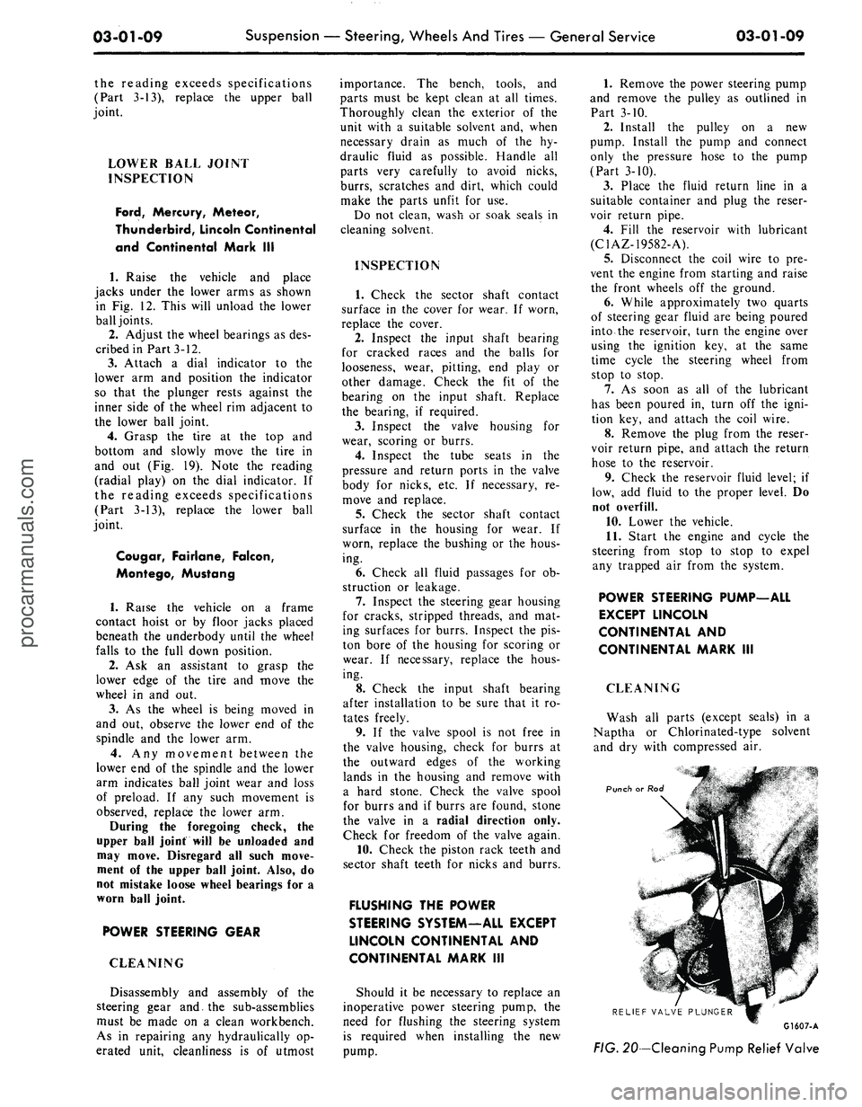
Wash all parts (except seals) in a
Naptha or Chlorinated-type solvent
and dry with compressed air.
Punch or Rod
RELIEF VALVE PLUNGER
G1607-A
FIG.
20—Cleaning Pump Relief Valveprocarmanuals.com
Page 140 of 413
03-07-02
Ford Design Non-Integral Power Steering System
03-07-02
PUMP AND RESERVOIR
CONTROL VALVE
POWER CYLINDER
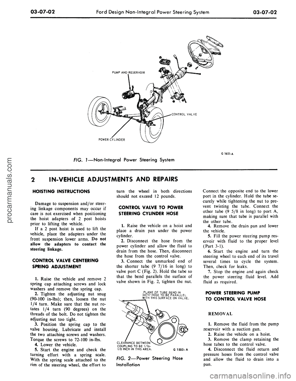
FIG. 7—Non-Integral Power Steering System
G 1651-A
IN-VEHICLE ADJUSTMENTS
AND
REPAIRS
HOISTING INSTRUCTIONS
Damage
to
suspension and/or steer-
ing linkage components
may
occur
if
care
is not
exercised when positioning
the hoist adapters
of 2
post hoists
prior
to
lifting
the
vehicle.
If
a 2
post hoist
is
used
to
lift
the
vehicle, place
the
adapters under
the
front suspension lower arms.
Do not
allow
the
adapters
to
contact
the
steering linkage.
CONTROL VALVE CENTERING
SPRING ADJUSTMENT
1.
Raise
the
vehicle
and
remove
2
spring
cap
attaching screws
and
lock
washers
and
remove
the
spring
cap.
2.
Tighten
the
adjusting
nut
snug
(90-100 in-lbs); then, loosen
the nut
1/4 turn. Make sure that
the nut ro-
tates
1/4
turn
(90
degrees)
on the
threads
of the
bolt.
Do not
tighten
the
adjusting
nut too
tight.
3.
Position
the
spring
cap to the
valve housing. Lubricate
and
install
the
two
attaching screws
and
washers.
Torque
the
screws
to
72-100 in-lbs.
4.
Lower
the
vehicle.
5.
Start
the
engine
and
check
the
turning effort with
a
spring scale.
With
the
spring scale attached
to the
rim
of the
steering wheel,
the
effort
to
turn
the
wheel
in
both directions
should
not
exceed
12
pounds.
CONTROL VALVE
TO
POWER
STEERING CYLINDER HOSE
1.
Raise
the
vehicle
on a
hoist
and
place
a
drain
pan
under
the
power
cylinder.
2.
Disconnect
the
hose from
the
power cylinder
and
allow
the
fluid
to
drain from
the
hose. Then, disconnect
the hose from
the
control valve.
3.
Connect
the
unmarked
end of
the shorter tube
(9 7/16 in
long)
to
valve port
C
(Fig. 2). Hold
the
tube
so
that
the
bend parallels
the
surface
of
valve shown
in Fig. 2,
tighten
the nut.
PLANE
OF
TUBE BEND
IN
3A717 HOSE
TO BE
PARALLEL
WITH THIS SURFACE ON VALVE.
CLEARANCE BETWEEN
COUPLING TO
BE 1/16-
1/8 INCH
IN
THIS AREA
G 1503-A
FIG. 2—Power Steering Hose
Installation
Connect
the
opposite
end to the
lower
port
in the
cylinder. Hold
the
tube
se-
curely while tightening
the nut to pre-
vent twisting
the
tube. Connect
the
other tube
(9 5/8 in
long)
to
port
A,
making sure that tube
is
parallel with
the other tube.
4.
Remove
the
drain
pan and
lower
the vehicle.
5.
Fill
the
power steering pump res-
ervoir with fluid
to the
proper level
(Part
3-1).
6. Start
the
engine
and
turn
the
steering wheel
to
each
end of its
travel
several times
to
cycle
the
system.
Then, check
for
leaks.
7.
Stop
the
engine
and
again check
the power steering fluid level.
Add
fluid
as
required.
POWER STEERING PUMP
TO CONTROL VALVE HOSE
REMOVAL
1.
Remove
the
fluid from
the
pump
reservoir with
a
suction
gun.
2.
Raise
the
vehicle
on a
hoist.
3.
Remove
the
clamp retaining
the
hose tubes
to the
control valve.
4.
Disconnect
the
fluid return
and
pressure hoses from
the
control valve
and allow
the
fluid
to
drain into
a
pan.procarmanuals.com
Page 141 of 413
03-07-03
Ford Design Non-Integral Power Steering System
03-07-03
5.
Lower the vehicle and disconnect
the fluid return hose from the reser-
voir.
6. Disconnect the fluid pressure
hose from the pump outlet fitting.
7.
Remove 1 bolt attaching the
hoses,
insulator, and the retainer to
the frame side rail and remove the
hoses,
and the insulator and retainer
as an assembly from the vehicle.
8. Remove the pressure and return
hoses from the retainer and insulator.
INSTALLATION
1.
Install the pressure and return
hoses in the insulator and retainer.
Paint stripe on pressure hose must be
aligned with slot in insulator. Paint or
tape band on return hose must be cen-
tered in insulator. Position the assem-
bly to the frame side rail and install
the attaching bolt.
2.
Place a hose clamp on the fluid
return hose and install the hose on the
power steering pump reservoir return
fitting.
3.
Torque the pump outlet fitting to
specification (Part 3-13). Then, con-
nect the pressure hose to the outlet fit-
ting and torque the fitting to specifica-
tion.
4.
Raise the vehicle and connect the
pressure and return lines to the con-
trol valve.
5.
Install the clamp to retain the
hose tubes to the control valve.
6. Lower the vehicle and fill the
power steering pump reservoir with
fluid, C1AZ-19582-A, to the proper
level (Part 3-1).
7.
Start the engine and turn the
steering wheel to each end of its travel
several times to cycle the system.
Then, check for fluid leaks.
8. Stop the engine and again check
the power steering fluid level (Part
3-1). Add fluid as required.
REMOVAL AND INSTALLATION
HOISTING INSTRUCTIONS
Damage to suspension and/or steer-
ing linkage components may occur if
care is not exercised when positioning
the hoist adapters of 2 post hoists
prior to lifting the vehicle.
If a 2 post hoist is used to lift the
vehicle, place the adapters under the
front suspension lower arms. Do not
allow the adapters to contact the
steering linkage.
STEERING GEAR
Refer to Group 3-6, Section 3 for
detailed instructions.
POWER STEERING PUMP
Refer to Group 3-10, Section 3 for
detailed instructions.
POWER STEERING CONTROL
VALVE
REMOVAL
1.
Disconnect the 4 fluid line fit-
tings at the control valve, and drain
the fluid from the lines. Turn the front
wheels to the left and right several
times to force all the fluid from the
system.
2.
Loosen the clamping nut and
bolt at the right end of the sleeve.
3.
Remove the roll pin from the
steering arm-to-idler arm rod -through
the slot in the sleeve.
4.
Remove the control valve ball
stud nut.
5.
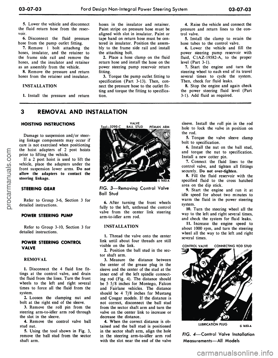
Using the tool shown in Fig. 3,
remove the ball stud from the sector
shaft arm.
VALVE
Too/-3290-C BALL STUD PITMAN ARM
FIG. 3—Removing Control Valve
Ball Stud
6. After turning the front wheels
fully to the left, unthread the control
valve from the center link steering
arm-to-idler arm rod.
INSTALLATION
1.
Thread the valve onto the center
link until about four threads are still
visible on the link.
2.
Position the ball stud in the sec-
tor shaft arm.
3.
Measure the distance between
the center of the grease plug in the
sleeve and the center of the stud at the
inner end of the left spindle connect-
ing rod (Fig. 4). The distance should
be 5 5/8 inches for Montego, Falcon
and Fairlane vehicles. The distance
should be 4 7/8 inches for Mustang
and Cougar models. If the distance is
not correct, disconnect the ball stud
from the sector shaft arm and turn the
valve on the center link to increase or
decrease the distance.
4.
When the correct distance is ob-
tained and the ball stud is positioned
in the sector shaft arm, align the hole
in the steering arm-to-idler arm rod
with the slot near the end of the valve
sleeve. Install the roll pin in the rod
hole to lock the valve in position on
the rod.
5.
Torque the valve sleeve clamp
bolt to specification.
6. Install the nut on the ball stud,
and torque the nut to specification.
Install a new cotter pin.
7.
Connect the fluid lines to the
control valve, and tighten all fittings
securely. Do not over-tighten.
8. Fill the fluid reservoir with the
specified fluid to the cross hatched
area on the dip stick.
9. Start the engine and run it at
idle speed for about two minutes to
warm the fluid in the power steering
system.
10.
Turn the steering wheel all the
way to the left and right several times,
and check the system for fluid leaks.
11.
Increase the engine speed to
about 1000 rpm, and turn the steering
wheel all the way to the left and right
several times.
CONTROL VALVE CONNECTING ROD STUD
LUBRICATION PLUG
G1653-A
FIG. 4—Control Valve Installation
Measurements—All Modelsprocarmanuals.com
Page 142 of 413
03-07-04
Ford Design Non-Integral Power Steering System
03-07-04
12.
Stop the engine, and check the
control valve and hose connections for
fluid leaks. Correct the cause of any
leaks.
13.
Check the fluid level, and refill
the reservoir if necessary.
14.
With the engine running check
the position of the steering wheel
when the front wheels are in the
straight-ahead position.Do not make
any adjustments until toe-in is
checked.
15.
Keep the engine running, and
check toe-in. If either toe-in or steer-
ing wheel position is not correct make
all necessary adjustments (Part 3-1) at
the spindle connecting rod sleeves.
16.
Check the effort to turn the
wheels in both directions. The effort
should be about equal in both direc-
tions.
POWER CYLINDER
REMOVAL
1.
Disconnect the two fluid lines
from the power cylinder and allow
them to drain into a container.
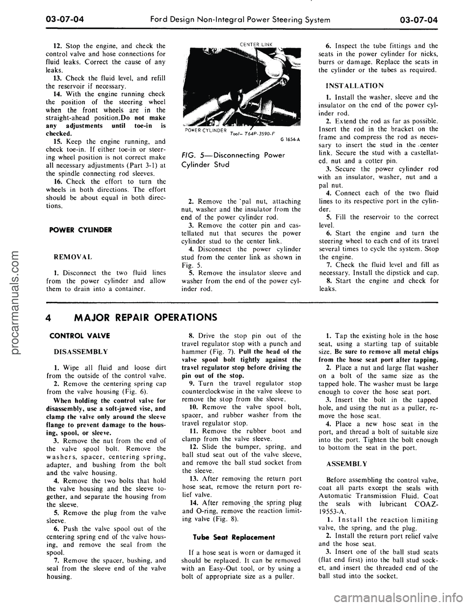
CENTER LINK
POWER CYLINDER
Tool- T64P-3590-F
G 1654-A
FIG. 5—Disconnecting Power
Cylinder Stud
2.
Remove the 'pal nut, attaching
nut, washer and the insulator from the
end of the power cylinder rod.
3.
Remove the cotter pin and cas-
tellated nut that secures the power
cylinder stud to the center link.
4.
Disconnect the power cylinder
stud from the center link as shown in
Fig. 5.
5.
Remove the insulator sleeve and
washer from the end of the power cyl-
inder rod.
6. Inspect the tube fittings and the
seats in the power cylinder for nicks,
burrs or damage. Replace the seats in
the cylinder or the tubes as required.
INSTALLATION
1.
Install the washer, sleeve and the
insulator on the end of the power cyl-
inder rod.
2.
Extend the rod as far as possible.
Insert the rod in the bracket on the
frame and compress the rod as neces-
sary to insert the stud in the -center
link. Secure the stud with a castellat-
ed, nut and a cotter pin.
3.
Secure the power cylinder rod
with an insulator, washer, nut and a
pal nut.
4.
Connect each of the two fluid
lines to its respective port in the cylin-
der.
5.
Fill the reservoir to the correct
level.
6. Start the engine and turn the
steering wheel to each end of its travel
several times to cycle the system. Stop
the engine.
7.
Check the fluid level and fill as
necessary. Install the dipstick and cap.
8. Start the engine and check for
leaks.
MAJOR REPAIR OPERATIONS
CONTROL VALVE
DISASSEMBLY
1.
Wipe all fluid and loose dirt
from the outside of the control valve.
2.
Remove the centering spring cap
from the valve housing (Fig. 6).
When holding the control valve for
disassembly, use a soft-jawed vise, and
clamp the valve only around the sleeve
flange to prevent damage to the hous-
ing, spool, or sleeve.
3.
Remove the nut from the end of
the valve spool bolt. Remove the
washers, spacer, centering spring,
adapter, and bushing from the bolt
and the valve housing.
4.
Remove the two bolts that hold
the valve housing and the sleeve to-
gether, and separate the housing from
the sleeve.
5.
Remove the plug from the valve
sleeve.
6. Push the valve spool out of the
centering spring end of the valve hous-
ing, and remove the seal from the
spool.
7.
Remove the spacer, bushing, and
seal from the sleeve end of the valve
housing.
8. Drive the stop pin out of the
travel regulator stop with a punch and
hammer (Fig. 7). Pull the head of the
valve spool bolt tightly against the
travel regulator stop before driving the
pin out of the stop.
9. Turn the travel regulator stop
counterclockwise in the valve sleeve to
remove the stop from the sleeve.
10.
Remove the valve spool bolt,
spacer, and rubber washer from the
travel regulator stop.
11.
Remove the rubber boot and
clamp from the valve sleeve.
12.
Slide the bumper, spring, and
ball stud seat out of the valve sleeve,
and remove the ball stud socket from
the sleeve.
13.
After removing the return port
hose seat, remove the return port re-
lief valve.
14.
After removing the spring plug
and O-ring, remove the reaction limit-
ing valve (Fig. 8).
Tube Seat Replacement
If a hose seat is worn or damaged it
should be replaced. It can be removed
with an Easy-Out tool, or by using a
bolt of appropriate size as a puller.
1.
Tap the existing hole in the hose
seat, using a starting tap of suitable
size.
Be sure to remove all metal chips
from the hose seat port after tapping.
2.
Place a nut and large flat washer
on a bolt of the same size as the
tapped hole. The washer must be large
enough to cover the hose seat port.
3.
Insert the bolt in the tapped
hole,
and using the nut as a puller, re-
move the hose seat.
4.
Place a new hose seat in the
port, and thread a bolt of suitable size
into the port. Tighten the bolt enough
to bottom the seat in the port.
ASSEMBLY
Before assembling the control valve,
coat all parts except the seals with
Automatic Transmission Fluid. Coat
the seals with lubricant COAZ-
19553-A.
1.
Install the reaction limiting
valve, the spring, and the plug.
2.
Install the return port relief valve
and the hose seat.
3.
Insert one of the ball stud seats
(flat end first) into the ball stud sock-
et, and insert the threaded end of the
ball stud into the socket.procarmanuals.com