FORD MUSTANG 2001 4.G User Guide
Manufacturer: FORD, Model Year: 2001, Model line: MUSTANG, Model: FORD MUSTANG 2001 4.GPages: 240, PDF Size: 2.11 MB
Page 11 of 240
Under engine misfire conditions, excessive
exhaust temperatures could damage the
catalytic converter, the fuel system, interior floor
coverings or other vehicle components, possibly
causing a fire.
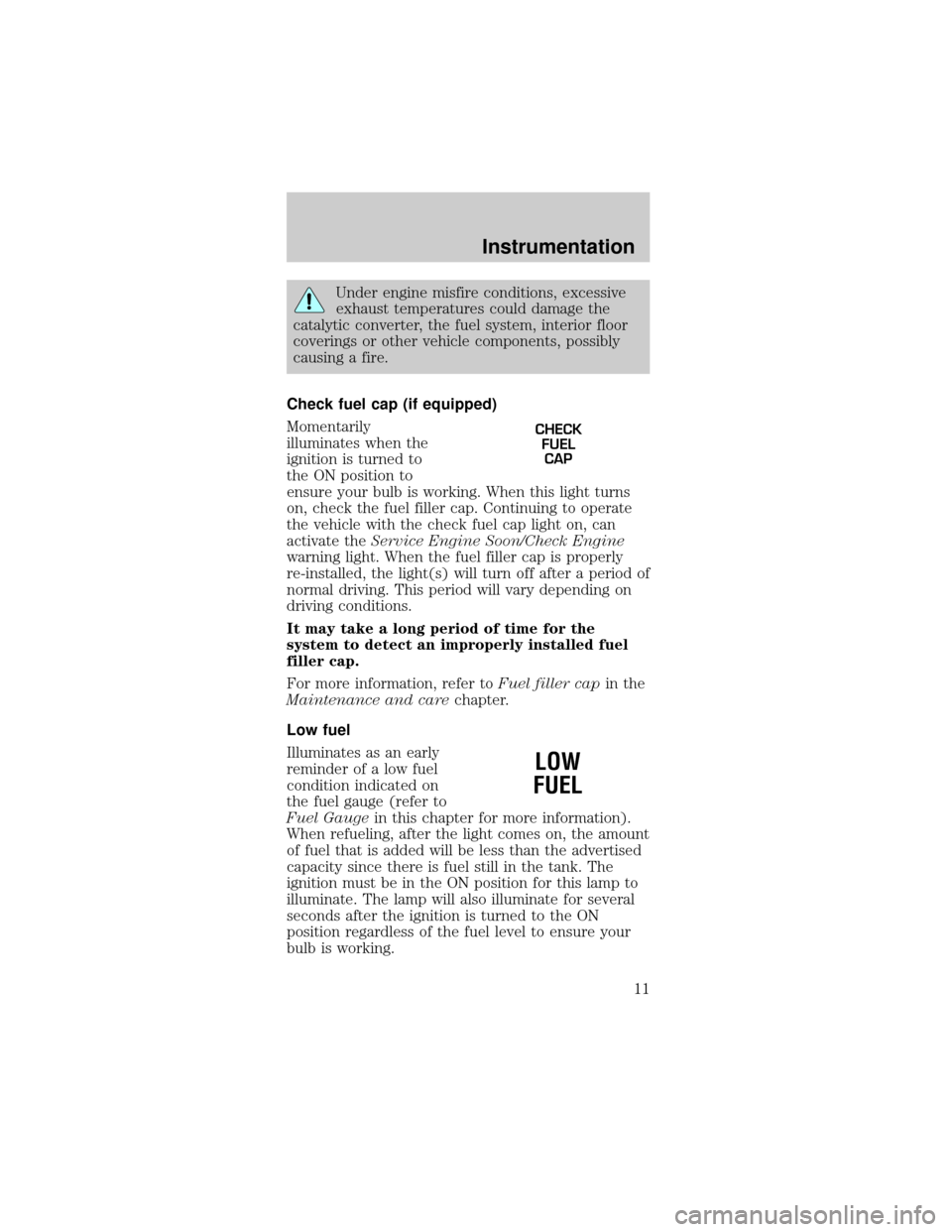
Check fuel cap (if equipped)
Momentarily
illuminates when the
ignition is turned to
the ON position to
ensure your bulb is working. When this light turns
on, check the fuel filler cap. Continuing to operate
the vehicle with the check fuel cap light on, can
activate theService Engine Soon/Check Engine
warning light. When the fuel filler cap is properly
re-installed, the light(s) will turn off after a period of
normal driving. This period will vary depending on
driving conditions.
It may take a long period of time for the
system to detect an improperly installed fuel
filler cap.
For more information, refer toFuel filler capin the
Maintenance and carechapter.
Low fuel
Illuminates as an early
reminder of a low fuel
condition indicated on
the fuel gauge (refer to
Fuel Gaugein this chapter for more information).
When refueling, after the light comes on, the amount
of fuel that is added will be less than the advertised
capacity since there is fuel still in the tank. The
ignition must be in the ON position for this lamp to
illuminate. The lamp will also illuminate for several
seconds after the ignition is turned to the ON
position regardless of the fuel level to ensure your
bulb is working.
CHECK
FUEL
CAP
LOW
FUEL
Instrumentation
11
Page 12 of 240
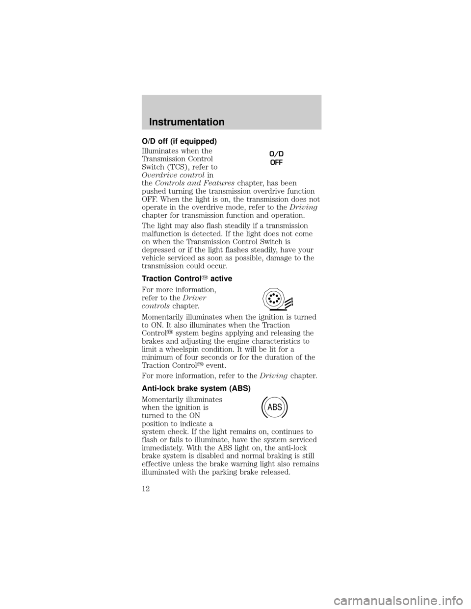
O/D off (if equipped)
Illuminates when the
Transmission Control
Switch (TCS), refer to
Overdrive controlin
theControls and Featureschapter, has been
pushed turning the transmission overdrive function
OFF. When the light is on, the transmission does not
operate in the overdrive mode, refer to theDriving
chapter for transmission function and operation.
The light may also flash steadily if a transmission
malfunction is detected. If the light does not come
on when the Transmission Control Switch is
depressed or if the light flashes steadily, have your
vehicle serviced as soon as possible, damage to the
transmission could occur.
Traction ControlYactive
For more information,
refer to theDriver
controlschapter.
Momentarily illuminates when the ignition is turned
to ON. It also illuminates when the Traction
Controlysystem begins applying and releasing the
brakes and adjusting the engine characteristics to
limit a wheelspin condition. It will be lit for a
minimum of four seconds or for the duration of the
Traction Controlyevent.
For more information, refer to theDrivingchapter.
Anti-lock brake system (ABS)
Momentarily illuminates
when the ignition is
turned to the ON
position to indicate a
system check. If the light remains on, continues to
flash or fails to illuminate, have the system serviced
immediately. With the ABS light on, the anti-lock
brake system is disabled and normal braking is still
effective unless the brake warning light also remains
illuminated with the parking brake released.
O/D
OFF
ABS
Instrumentation
12
Page 13 of 240
Brake system warning
Momentarily illuminates
when the ignition is
turned to the ON
position to ensure the
circuit is functional. Also illuminates if the parking
brake is engaged. If brake warning lamp does not
illuminate at these times, seek service immediately.
Illumination after releasing the parking brake
indicates low brake fluid level and the brake system
should be inspected immediately.
Safety belt warning chime
Sounds to remind you to fasten your safety belts.
For information on the safety belt warning chime,
refer to theSeating and safety restraintschapter.
Belt minder chime
Sounds intermittently to remind you to fasten your
safety belts.
For information on the safety belt minder chime,
refer to theSeating and safety restraintschapter.
Supplemental restraint system (SRS) warning
chime
For information on the SRS warning chime, refer to
theSeating and safety restraintschapter.
Key-in-ignition warning chime
Sounds when the key is left in the ignition in the
OFF/LOCK or ACC position and the driver's door is
opened.
Headlamps on warning chime
Sounds when the headlamps or parking lamps are
on, the ignition is off (and the key is not in the
ignition) and the driver's door is opened.
P!
BRAKE
Instrumentation
13
Page 14 of 240
GAUGES
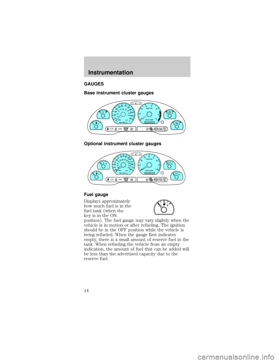
Base instrument cluster gauges
Optional instrument cluster gauges
Fuel gauge
Displays approximately
how much fuel is in the
fuel tank (when the
key is in the ON
position). The fuel gauge may vary slightly when the
vehicle is in motion or after refueling. The ignition
should be in the OFF position while the vehicle is
being refueled. When the gauge first indicates
empty, there is a small amount of reserve fuel in the
tank. When refueling the vehicle from an empty
indication, the amount of fuel that can be added will
be less than the advertised capacity due to the
reserve fuel.
P! BRAKE
L C
EFH
LH
10 203020 406080100
120
140
160
180
405060 70
80
90
100
11 0
1204
5
6
7 3
2
1
H
THEFT
RPMX1000
FUEL DOORSELECT/RESET
LOW
FUELO/D
OFF AIR
BAGSERVICE
ENGINE
SOON
MPH km/h
ABS
00000 00.
CHECK
FUEL
CAP
P! BRAKE
0
00000 00
FH
H
102040608020 40608010 012 0 14 0
160
180
200
220
240
100
120
140
305070 90
110
13 0
1504
5
6
7
8 3
2
1
H
THEFT
RPMX1000
FUEL DOORSELECT/RESET
LOW
FUELO/D
OFF AIR
BAGSERVICE
ENGINE
SOON
MPH km/h
ABS
.
L
LCHECK
FUEL
CAP
F
Instrumentation
14
Page 15 of 240
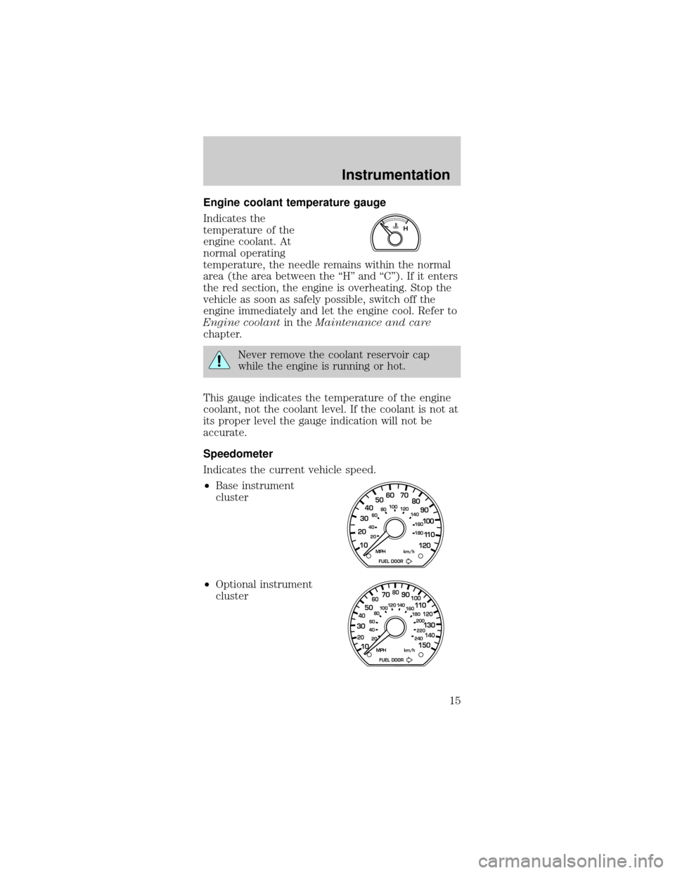
Engine coolant temperature gauge
Indicates the
temperature of the
engine coolant. At
normal operating
temperature, the needle remains within the normal
area (the area between the ªHº and ªCº). If it enters
the red section, the engine is overheating. Stop the
vehicle as soon as safely possible, switch off the
engine immediately and let the engine cool. Refer to
Engine coolantin theMaintenance and care
chapter.
Never remove the coolant reservoir cap
while the engine is running or hot.
This gauge indicates the temperature of the engine
coolant, not the coolant level. If the coolant is not at
its proper level the gauge indication will not be
accurate.
Speedometer
Indicates the current vehicle speed.
²Base instrument
cluster
²Optional instrument
cluster
CH
10 203020 406080100
120
140
160
180
405060 70
80
90
100
11 0
120
FUEL DOOR MPH km/h
102040608020 40608010 012 0 14 0
160
180
200
220
240
100
120
140
305070 90
110
13 0
150
FUEL DOOR MPH km/h
Instrumentation
15
Page 16 of 240
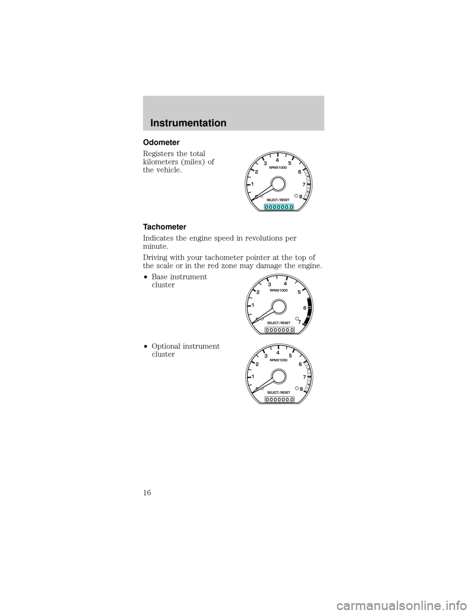
Odometer
Registers the total
kilometers (miles) of
the vehicle.
Tachometer
Indicates the engine speed in revolutions per
minute.
Driving with your tachometer pointer at the top of
the scale or in the red zone may damage the engine.
²Base instrument
cluster
²Optional instrument
cluster
0
00000 00
4
5
6
7
8 3
2
1RPMX1000
SELECT/RESET
.
0
00000 00
4
5
6
7 3
2
1RPMX1000
SELECT/RESET
.
0
00000 00
4
5
6
7
8 3
2
1RPMX1000
SELECT/RESET
.
Instrumentation
16
Page 17 of 240
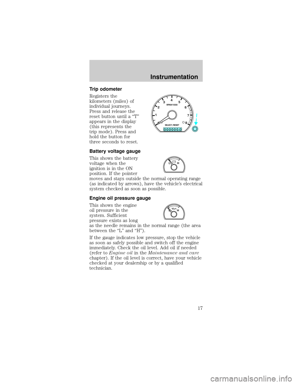
Trip odometer
Registers the
kilometers (miles) of
individual journeys.
Press and release the
reset button until a ªTº
appears in the display
(this represents the
trip mode). Press and
hold the button for
three seconds to reset.
Battery voltage gauge
This shows the battery
voltage when the
ignition is in the ON
position. If the pointer
moves and stays outside the normal operating range
(as indicated by arrows), have the vehicle's electrical
system checked as soon as possible.
Engine oil pressure gauge
This shows the engine
oil pressure in the
system. Sufficient
pressure exists as long
as the needle remains in the normal range (the area
between the ªLº and ªHº).
If the gauge indicates low pressure, stop the vehicle
as soon as safely possible and switch off the engine
immediately. Check the oil level. Add oil if needed
(refer toEngine oilin theMaintenance and care
chapter). If the oil level is correct, have your vehicle
checked at your dealership or by a qualified
technician.
0
00000 00
4
5
6
7
8 3
2
1RPMX1000
SELECT/RESET
.
LH
LH
Instrumentation
17
Page 18 of 240
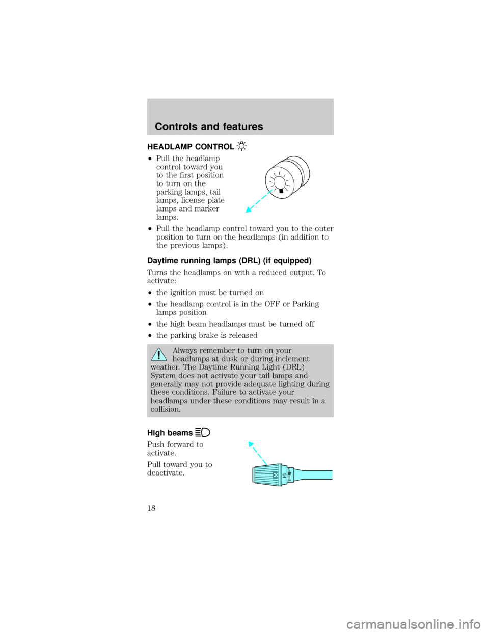
HEADLAMP CONTROL
²Pull the headlamp
control toward you
to the first position
to turn on the
parking lamps, tail
lamps, license plate
lamps and marker
lamps.
²Pull the headlamp control toward you to the outer
position to turn on the headlamps (in addition to
the previous lamps).
Daytime running lamps (DRL) (if equipped)
Turns the headlamps on with a reduced output. To
activate:
²the ignition must be turned on
²the headlamp control is in the OFF or Parking
lamps position
²the high beam headlamps must be turned off
²the parking brake is released
Always remember to turn on your
headlamps at dusk or during inclement
weather. The Daytime Running Light (DRL)
System does not activate your tail lamps and
generally may not provide adequate lighting during
these conditions. Failure to activate your
headlamps under these conditions may result in a
collision.
High beams
Push forward to
activate.
Pull toward you to
deactivate.
OFFHI
LO
Controls and features
18
Page 19 of 240
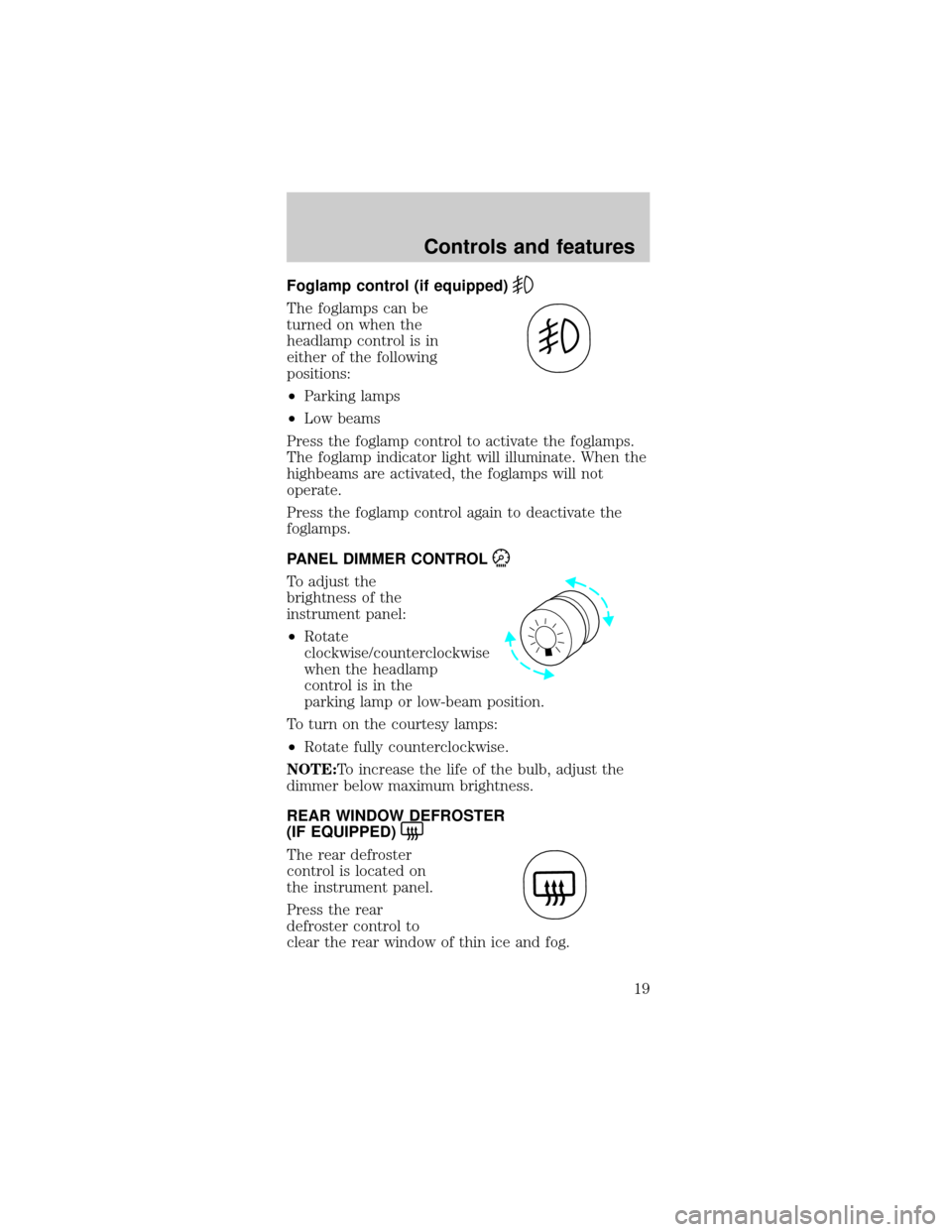
Foglamp control (if equipped)
The foglamps can be
turned on when the
headlamp control is in
either of the following
positions:
²Parking lamps
²Low beams
Press the foglamp control to activate the foglamps.
The foglamp indicator light will illuminate. When the
highbeams are activated, the foglamps will not
operate.
Press the foglamp control again to deactivate the
foglamps.
PANEL DIMMER CONTROL
To adjust the
brightness of the
instrument panel:
²Rotate
clockwise/counterclockwise
when the headlamp
control is in the
parking lamp or low-beam position.
To turn on the courtesy lamps:
²Rotate fully counterclockwise.
NOTE:To increase the life of the bulb, adjust the
dimmer below maximum brightness.
REAR WINDOW DEFROSTER
(IF EQUIPPED)
The rear defroster
control is located on
the instrument panel.
Press the rear
defroster control to
clear the rear window of thin ice and fog.
Controls and features
19
Page 20 of 240
²A small LED will illuminate when the rear
defroster is activated.
The ignition must be in the ON position to operate
the rear window defroster.
The defroster turns off automatically after 10
minutes or when the ignition is turned to the OFF
position. To manually turn off the defroster before
10 minutes have passed, push the control again.
CLIMATE CONTROL SYSTEM
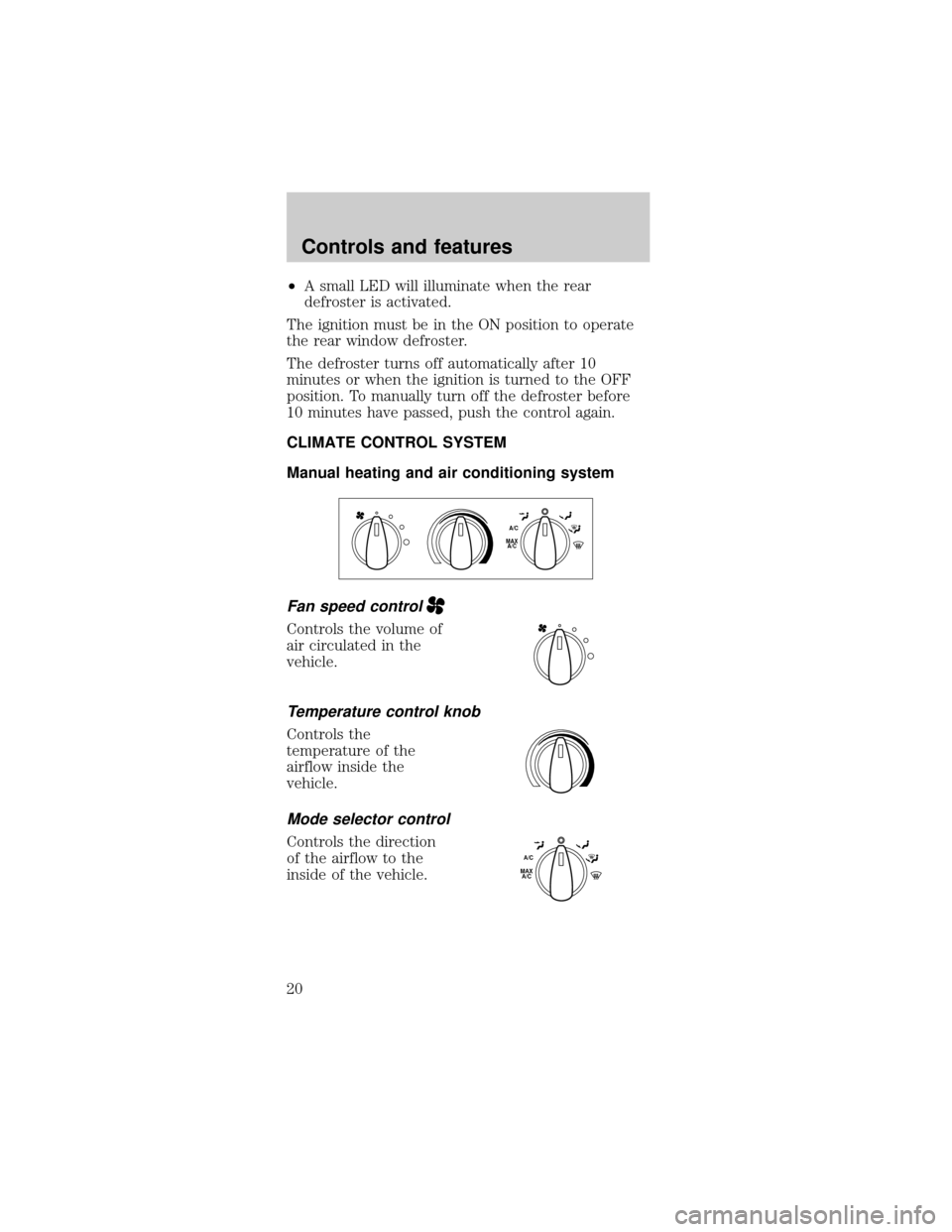
Manual heating and air conditioning system
Fan speed control
Controls the volume of
air circulated in the
vehicle.
Temperature control knob
Controls the
temperature of the
airflow inside the
vehicle.
Mode selector control
Controls the direction
of the airflow to the
inside of the vehicle.
MAX
A/CA/C
MAX
A/CA/C
Controls and features
20