FORD MUSTANG 2003 Workshop Manual
MUSTANG 2003
FORD
FORD
https://www.carmanualsonline.info/img/11/56942/w960_56942-0.png
FORD MUSTANG 2003 Workshop Manual
Page 1672 of 4378
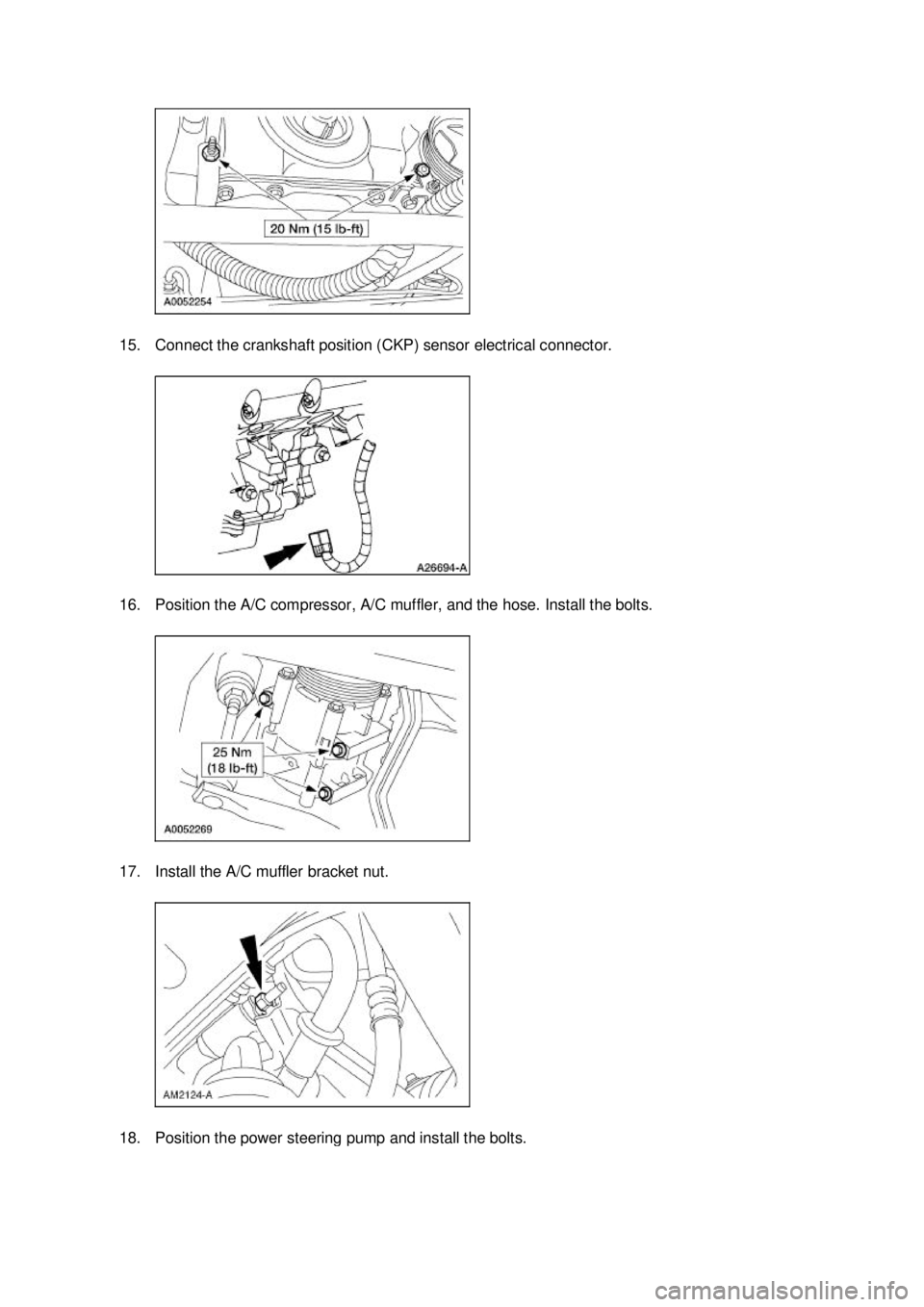
15. Connect the crankshaft position (CKP) sensor electrical connector.
16. Position the A/C compressor, A/C muffler, and the hose. Install the bolts.
17. Install the A/C muffler bracket nut.
18. Position the power steering pump and install the bolts. �K�l�j . 15 �b�a
212003 Mustang Workshop Manual
17. 11. 2011file:///C:/Ford/2000 - 2004/tsocache/SHEF_4464/S3B~us~en~ ...
Page 1679 of 4378
IN-
VEHICLE REPAIR
Timing Drive Components
Removal CAUTION: Since the engine is not free- wheeling, if the crankshaft or the camshafts are
moved in any manner during removal and installation, the crankshaft and the camshafts must
be re- synchronized.
1. Remove the engine front cover. For additional information, refer to Engine Front Cover in this
section.
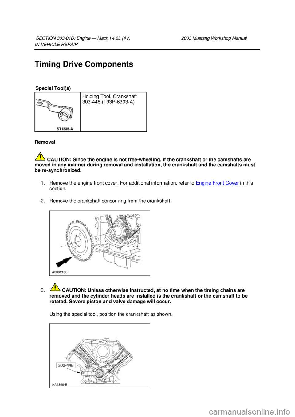
2. Remove the crankshaft sensor ring from the crankshaft.
3. CAUTION: Unless otherwise instructed, at no time when the timing chains are
removed and the cylinder heads are installed is the crankshaft or the camshaft to be
rotated. Severe piston and valve damage will occur.
Using the special tool, position the crankshaft as shown.
SECTION 303-
01D: Engine — Mach I 4.6L (4V) 2003 Mustang Workshop Manual Special Tool(s)
Holding Tool, Crankshaft
303-
448 (T93P-6303- A) �K�l�j . 1 �b�a
72003 Mustang Workshop Manual
17. 11. 2011file:///C:/Ford/2000 - 2004/tsocache/SHEF_4464/S3B~us~en~ ...
Page 1684 of 4378
11.
NOTE: LH shown; RH similar.
Position the tensioner arms and tensioners, and install the bolts.
12. Remove the retaining clips from the timing chain tensioners.
13. Position the crankshaft sensor ring on the crankshaft.
14. Install the engine front cover. For additional information, refer to Engine Front Cover in this
section. �K�l�j . 6 �b�a
72003 Mustang Workshop Manual
17. 11. 2011file:///C:/Ford/2000 - 2004/tsocache/SHEF_4464/S3B~us~en~ ...
Page 1738 of 4378
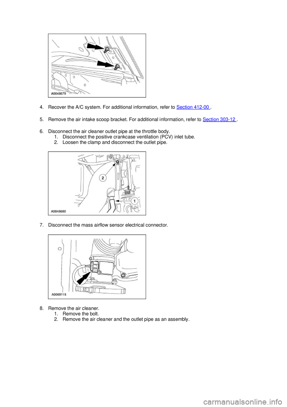
4. Recover the A/C system. For additional information, refer to
Section 412 - 00 .
5. Remove the air intake scoop bracket. For additional information, refer to Section 303 - 12 .
6. Disconnect the air cleaner outlet pipe at the throttle body. 1. Disconnect the positive crankcase ventilation (PCV) inlet tube.
2. Loosen the clamp and disconnect the outlet pipe.
7. Disconnect the mass airflow sensor electrical connector.
8. Remove the air cleaner. 1. Remove the bolt.
2. Remove the air cleaner and the outlet pipe as an assembly. �K�l�j . 2 �b�a
192003 Mustang Workshop Manual
17. 11. 2011file:///C:/Ford/2000 - 2004/tsocache/SHEF_4464/S3B~us~en~ ...
Page 1740 of 4378
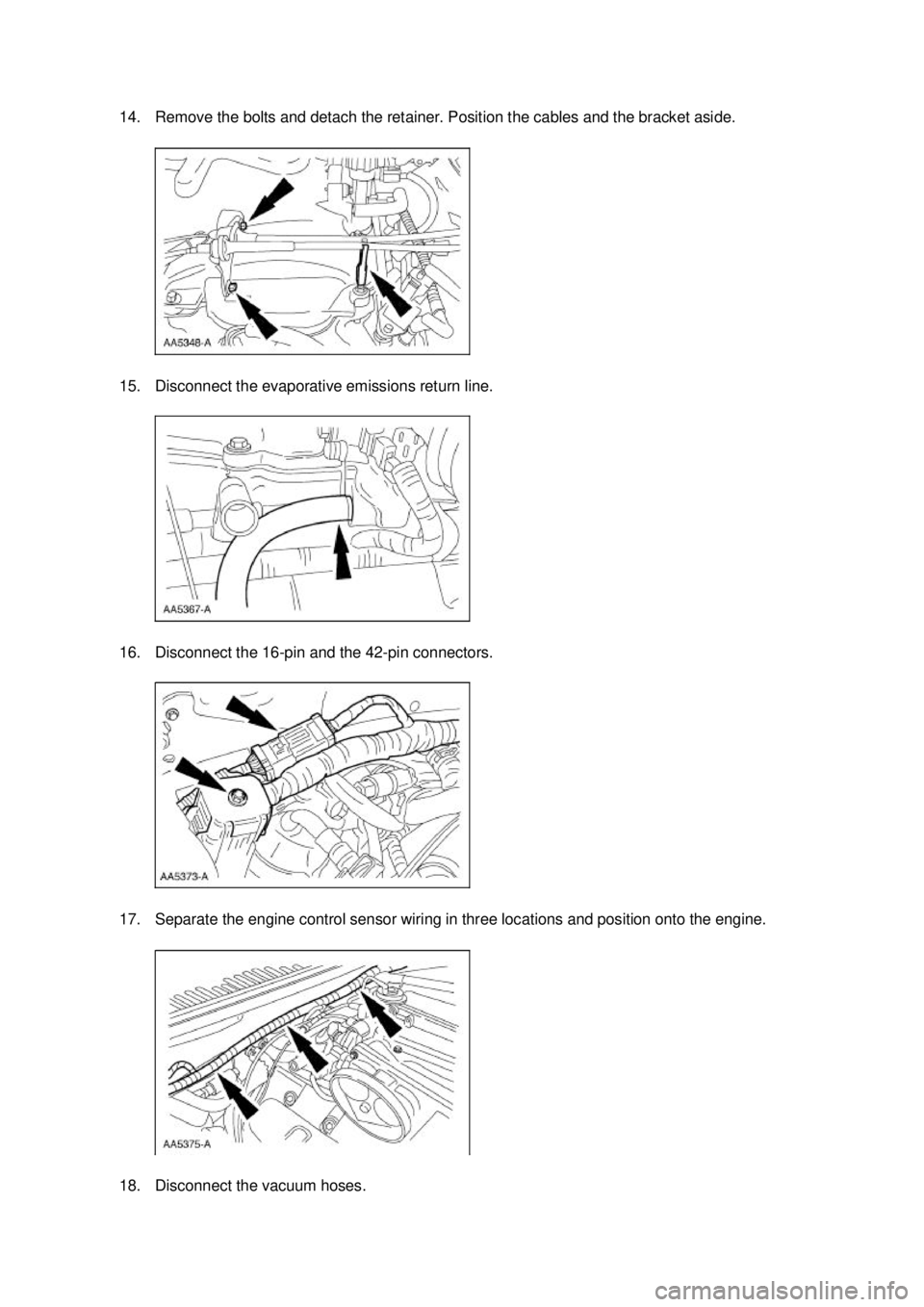
14. Remove the bolts and detach the retainer. Position the cables and the bracket aside.
15. Disconnect the evaporative emissions return line.
16. Disconnect the 16-
pin and the 42-pin connectors.
17. Separate the engine control sensor wiring in three locations and position onto the engine.
18. Disconnect the vacuum hoses. �K�l�j . 4 �b�a
192003 Mustang Workshop Manual
17. 11. 2011file:///C:/Ford/2000 - 2004/tsocache/SHEF_4464/S3B~us~en~ ...
Page 1748 of 4378
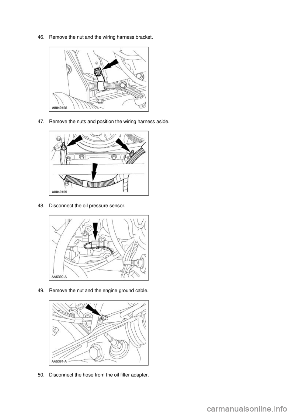
46. Remove the nut and the wiring harness bracket.
47. Remove the nuts and position the wiring harness aside.
48. Disconnect the oil pressure sensor.
49. Remove the nut and the engine ground cable.
50. Disconnect the hose from the oil filter adapter. �K�l�j . 12 �b�a
192003 Mustang Workshop Manual
17. 11. 2011file:///C:/Ford/2000 - 2004/tsocache/SHEF_4464/S3B~us~en~ ...
Page 1751 of 4378
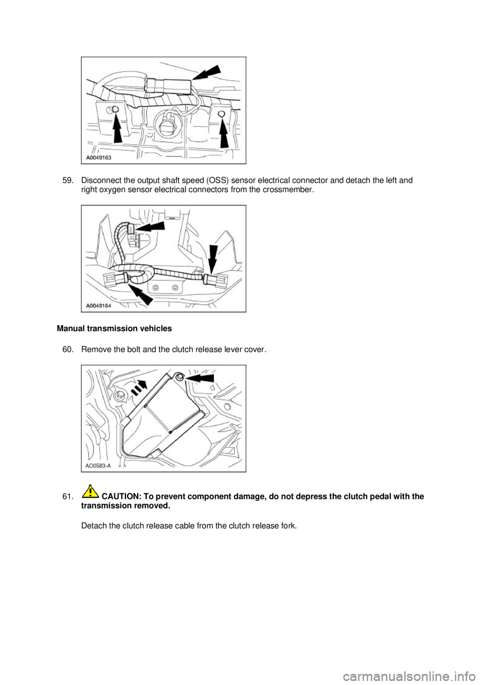
59. Disconnect the output shaft speed (OSS) sensor electrical connector and detach the left and
right oxygen sensor electrical connectors from the crossmember.
Manual transmission vehicles 60. Remove the bolt and the clutch release lever cover.
61. CAUTION: To prevent component damage, do not depress the clutch pedal with the
transmission removed.
Detach the clutch release cable from the clutch release fork. �K�l�j . 15 �b�a
192003 Mustang Workshop Manual
17. 11. 2011file:///C:/Ford/2000 - 2004/tsocache/SHEF_4464/S3B~us~en~ ...
Page 1753 of 4378
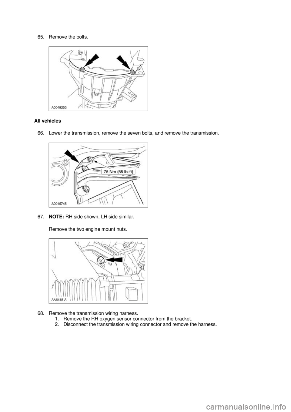
65. Remove the bolts.
All vehicles 66. Lower the transmission, remove the seven bolts, and remove the transmission.
67. NOTE: RH side shown, LH side similar.
Remove the two engine mount nuts.
68. Remove the transmission wiring harness. 1. Remove the RH oxygen sensor connector from the bracket.
2. Disconnect the transmission wiring connector and remove the harness. �K�l�j . 17 �b�a
192003 Mustang Workshop Manual
17. 11. 2011file:///C:/Ford/2000 - 2004/tsocache/SHEF_4464/S3B~us~en~ ...
Page 1761 of 4378
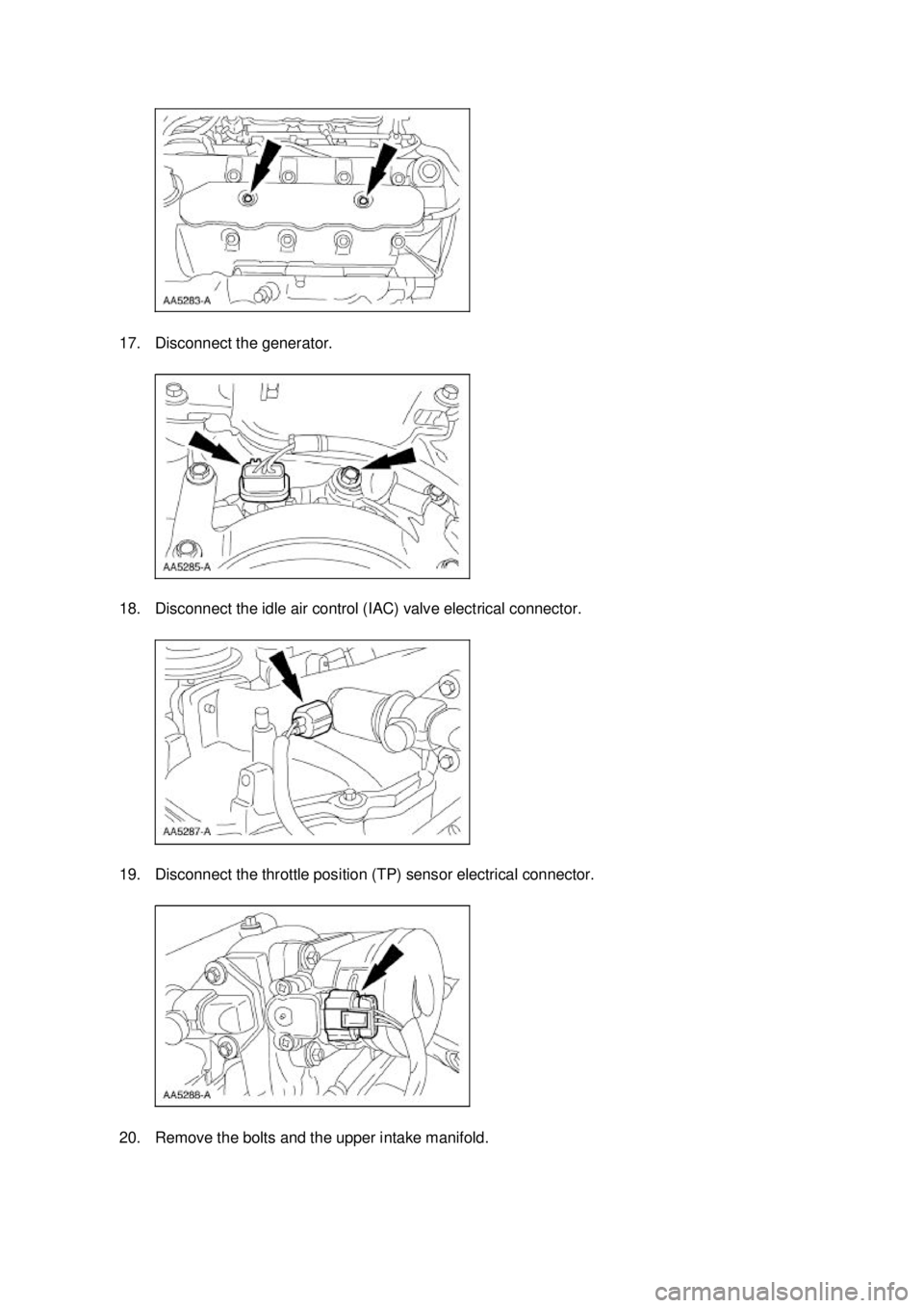
17. Disconnect the generator.
18. Disconnect the idle air control (IAC) valve electrical connector.
19. Disconnect the throttle position (TP) sensor electrical connector.
20. Remove the bolts and the upper intake manifold. �K�l�j . 6 �b�a
212003 Mustang Workshop Manual
17. 11. 2011file:///C:/Ford/2000 - 2004/tsocache/SHEF_4464/S3B~us~en~ ...
Page 1763 of 4378
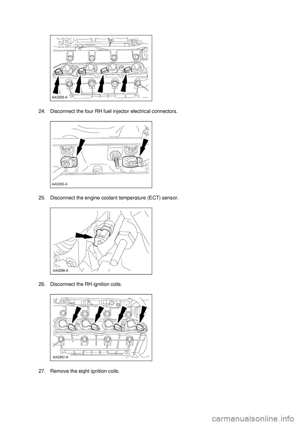
24. Disconnect the four RH fuel injector electrical connectors.
25. Disconnect the engine coolant temperature (ECT) sensor.
26. Disconnect the RH ignition coils.
27. Remove the eight ignition coils. �K�l�j . 8 �b�a
212003 Mustang Workshop Manual
17. 11. 2011file:///C:/Ford/2000 - 2004/tsocache/SHEF_4464/S3B~us~en~ ...
