FORD POLICE INTERCEPTOR 2021 Workshop Manual
Manufacturer: FORD, Model Year: 2021, Model line: POLICE INTERCEPTOR, Model: FORD POLICE INTERCEPTOR 2021Pages: 412, PDF Size: 7.51 MB
Page 51 of 412
The restraints control module also
monitors the readiness of the above safety
devices plus the crash and occupant
sensors. The readiness of the safety
system is indicated by a warning indicator
light in the instrument cluster or by a
backup tone if the warning light is not
working. Routine maintenance of the
airbag is not required.
A difficulty with the system is indicated by
one or more of the following:
•
The readiness light either flashes or
stays lit.
• A series of five beeps will be heard. The
tone pattern repeats periodically until
the problem, the light or both are
repaired. •
The readiness light will not illuminate
immediately after you switch the
ignition on.
If any of these things happen, even
intermittently, have the supplemental
restraint system serviced at an authorized
dealer immediately. Unless serviced, the
system may not function properly in the
event of a crash.
The seatbelt pretensioners and the airbag
supplemental restraint system are
designed to activate when the vehicle
sustains frontal or sideways deceleration
sufficient to cause the restraints control
module to deploy a safety device or when
a certain likelihood of a rollover event is
detected by the rollover sensor. The fact that the seatbelt pretensioners
or airbags did not activate for both front
seat occupants in a crash does not mean
that something is wrong with the system.
Rather, it means the restraints control
module determined the accident
conditions (crash severity, belt usage)
were not appropriate to activate these
safety devices.
•
The design of the front airbags is to
activate only in frontal and near-frontal
crashes (not rollovers, side impacts or
rear impacts) unless the crash causes
sufficient frontal deceleration.
• The design of the seatbelt
pretensioners is to activate in frontal,
near-frontal and side crashes and in
rollovers.
• The design of the side airbags is to
inflate in certain side impact crashes
and in rollovers. Side airbags may
activate in other types of crashes if the
vehicle experiences sufficient sideways
motion or deformation.
• The knee airbag(s) may deploy based
on crash severity and occupant
conditions.
• The design of the Safety Canopy is to
inflate in certain side impact crashes
or rollover events. The Safety Canopy
may activate in other types of crashes
if the vehicle experiences sufficient
sideways motion or deformation, or a
certain likelihood of rollover.
Airbags and Police Equipment WARNING: Do not place objects
or mount equipment on or near the
airbag cover, on the side of the front or
rear seatbacks, or in areas that may
come into contact with a deploying
airbag. Failure to follow these
instructions may increase the risk of
personal injury in the event of a crash.
48
Explorer (CTW) Police, Canada/United States of America, Police, enUSA, Edition date: 202007, Second-Printing Supplementary Restraints SystemE67017
Page 52 of 412
WARNING: Keep the areas in front
of the airbags free from obstruction. Do
not affix anything to or over the airbag
covers. Objects could become projectiles
during airbag deployment. Failure to
follow this instruction could result in
personal injury or death.
Dual driver and passenger airbags, side
airbags and knee airbags affect the way
police equipment can be mounted in police
vehicles.
Any surfaces that could come into contact
with an airbag, once it has deployed, must
not damage the airbag or alter its
deployment path.
Once the airbag has fully deployed, any
peripheral equipment surfaces that could
come into contact with the airbag (such
as when the airbag deflates with the
loading of an occupant) must not damage
the airbag or alter its deployment path.
Sharp edges, corners or protrusions could
damage the nylon airbag material and
reduce the effectiveness of the airbag.
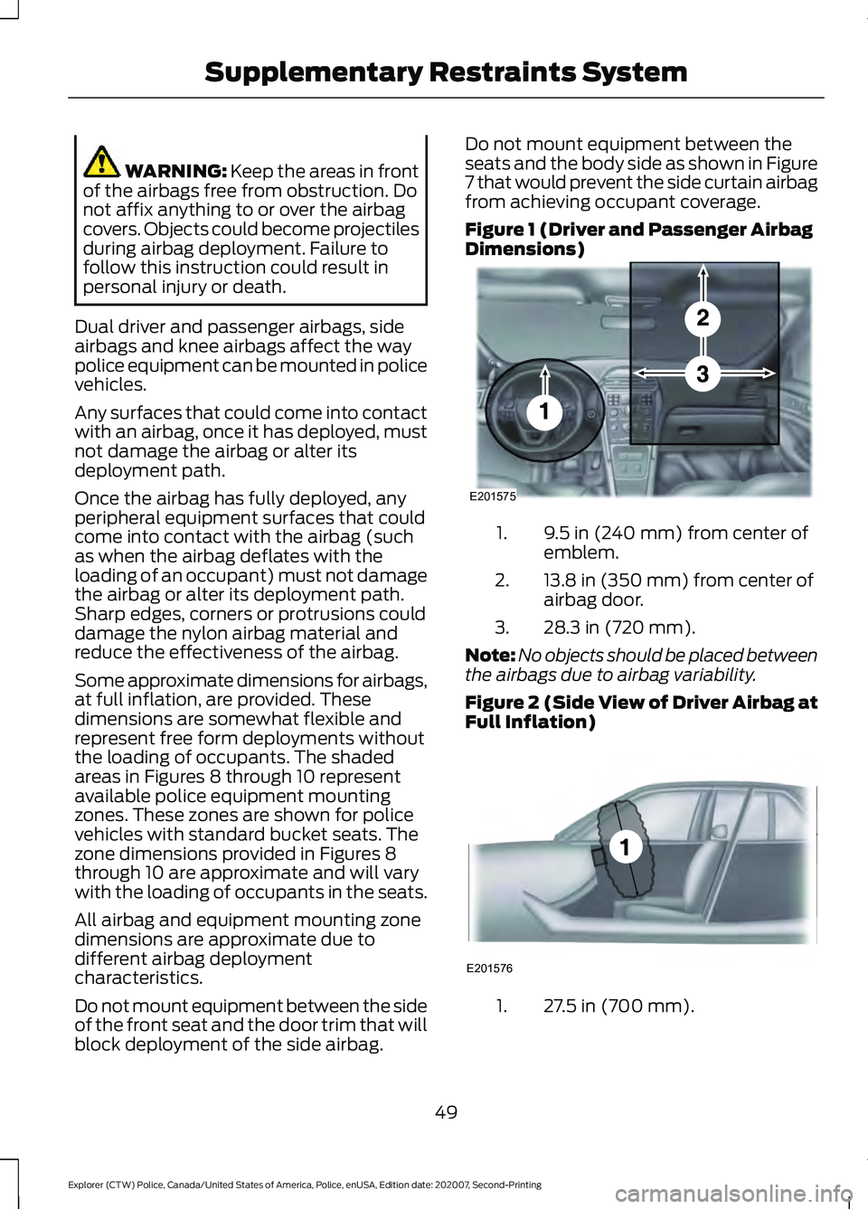
Some approximate dimensions for airbags,
at full inflation, are provided. These
dimensions are somewhat flexible and
represent free form deployments without
the loading of occupants. The shaded
areas in Figures 8 through 10 represent
available police equipment mounting
zones. These zones are shown for police
vehicles with standard bucket seats. The
zone dimensions provided in Figures 8
through 10 are approximate and will vary
with the loading of occupants in the seats.
All airbag and equipment mounting zone
dimensions are approximate due to
different airbag deployment
characteristics.
Do not mount equipment between the side
of the front seat and the door trim that will
block deployment of the side airbag. Do not mount equipment between the
seats and the body side as shown in Figure
7 that would prevent the side curtain airbag
from achieving occupant coverage.
Figure 1 (Driver and Passenger Airbag
Dimensions)
9.5 in (240 mm) from center of
emblem.
1.
13.8 in (350 mm) from center of
airbag door.
2.
28.3 in (720 mm).
3.
Note: No objects should be placed between
the airbags due to airbag variability.
Figure 2 (Side View of Driver Airbag at
Full Inflation) 27.5 in (700 mm).
1.
49
Explorer (CTW) Police, Canada/United States of America, Police, enUSA, Edition date: 202007, Second-Printing Supplementary Restraints SystemE201575 E201576
Page 53 of 412
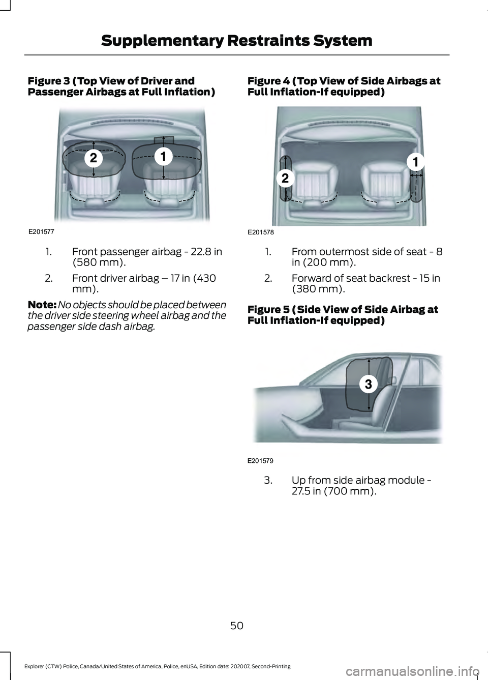
Figure 3 (Top View of Driver and
Passenger Airbags at Full Inflation)
Front passenger airbag - 22.8 in
(580 mm).
1.
Front driver airbag – 17 in (430
mm).
2.
Note: No objects should be placed between
the driver side steering wheel airbag and the
passenger side dash airbag. Figure 4 (Top View of Side Airbags at
Full Inflation-If equipped) From outermost side of seat - 8
in (200 mm).
1.
Forward of seat backrest - 15 in
(380 mm).
2.
Figure 5 (Side View of Side Airbag at
Full Inflation-If equipped) Up from side airbag module -
27.5 in (700 mm).
3.
50
Explorer (CTW) Police, Canada/United States of America, Police, enUSA, Edition date: 202007, Second-Printing Supplementary Restraints SystemE201577 E201578 E201579
Page 54 of 412
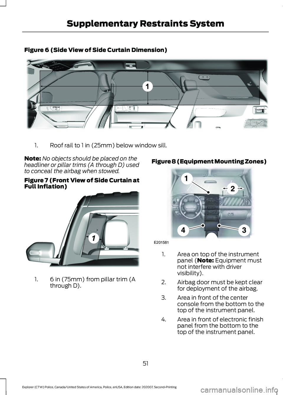
Figure 6 (Side View of Side Curtain Dimension)
Roof rail to 1 in (25mm) below window sill.
1.
Note: No objects should be placed on the
headliner or pillar trims (A through D) used
to conceal the airbag when stowed.
Figure 7 (Front View of Side Curtain at
Full Inflation) 6 in (75mm) from pillar trim (A
through D).
1. Figure 8 (Equipment Mounting Zones) Area on top of the instrument
panel (Note: Equipment must
not interfere with driver
visibility).
1.
Airbag door must be kept clear
for deployment of the airbag.
2.
Area in front of the center
console from the bottom to the
top of the instrument panel.
3.
Area in front of electronic finish
panel from the bottom to the
top of the instrument panel.
4.
51
Explorer (CTW) Police, Canada/United States of America, Police, enUSA, Edition date: 202007, Second-Printing Supplementary Restraints SystemE301094 E301077 E201581
Page 55 of 412
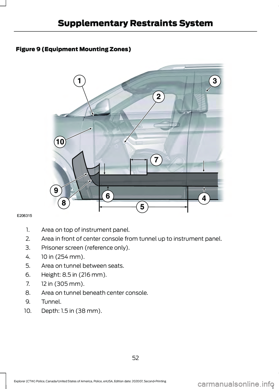
Figure 9 (Equipment Mounting Zones)
Area on top of instrument panel.
1.
Area in front of center console from tunnel up to instrument panel.
2.
Prisoner screen (reference only).
3.
10 in (254 mm).
4.
Area on tunnel between seats.
5.
Height: 8.5 in (216 mm).
6.
12 in (305 mm).
7.
Area on tunnel beneath center console.
8.
Tunnel.
9.
Depth: 1.5 in (38 mm).
10.
52
Explorer (CTW) Police, Canada/United States of America, Police, enUSA, Edition date: 202007, Second-Printing Supplementary Restraints SystemE206315
Page 56 of 412
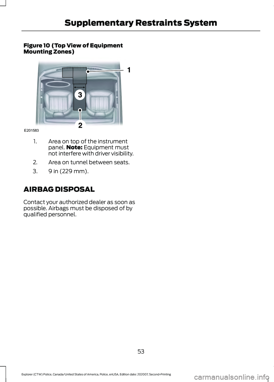
Figure 10 (Top View of Equipment
Mounting Zones)
Area on top of the instrument
panel.
Note: Equipment must
not interfere with driver visibility.
1.
Area on tunnel between seats.
2.
9 in (229 mm).
3.
AIRBAG DISPOSAL
Contact your authorized dealer as soon as
possible. Airbags must be disposed of by
qualified personnel.
53
Explorer (CTW) Police, Canada/United States of America, Police, enUSA, Edition date: 202007, Second-Printing Supplementary Restraints SystemE201583
Page 57 of 412
PEDESTRIAN ALERT SYSTEM
Due to the quiet operation of hybrid and
electric vehicles at low speeds, the system
creates a subtle sound to alert pedestrians.
The system is on when your vehicle is
running and not in park (P). Some sound
may be audible in the passenger
compartment.
54
Explorer (CTW) Police, Canada/United States of America, Police, enUSA, Edition date: 202007, Second-Printing Pedestrian Protection - Hybrid Electric Vehicle (HEV)
Page 58 of 412
GENERAL INFORMATION ON
RADIO FREQUENCIES
This device complies with Part 15 of the
FCC Rules and with Licence exempt RSS
Standards of Industry Canada. Operation
is subject to the following two conditions:
•
This device may not cause harmful
interference, and
• This device must accept any
interference received, including
interference that may cause undesired
operation. WARNING: Changes or
modifications not expressively approved
by the party responsible for compliance
could void the user's authority to operate
the equipment. The term "IC:" before the
radio certification number only signifies
that Industry Canada technical
specifications were met.
The typical operating range for your
transmitter is approximately
33 ft (10 m).
Vehicles with the remote start feature will
have a greater range. One of the following
could cause a decrease in operating range:
• Weather conditions.
• Nearby radio towers.
• Structures around the vehicle.
• Other vehicles parked next to your
vehicle.
Other short distance radio transmissions,
for example amateur radios, medical
equipment, wireless headphones, remote
controls and alarm systems can also use
the radio frequency used by your remote
control. If the frequencies are jammed, you
will not be able to use your remote control.
You can lock and unlock the doors with the
key.
Note: Make sure to lock your vehicle before
leaving it unattended. Note:
If you are in range, the remote control
will operate if you press any button
unintentionally.
Note: The remote control contains sensitive
electrical components. Exposure to moisture
or impact may cause permanent damage.
REMOTE CONTROL
(IF EQUIPPED)
Note: If there is a problem with the remote
entry system, make sure to take all remote
controls with you to an authorized dealer in
order to aid in troubleshooting the problem.
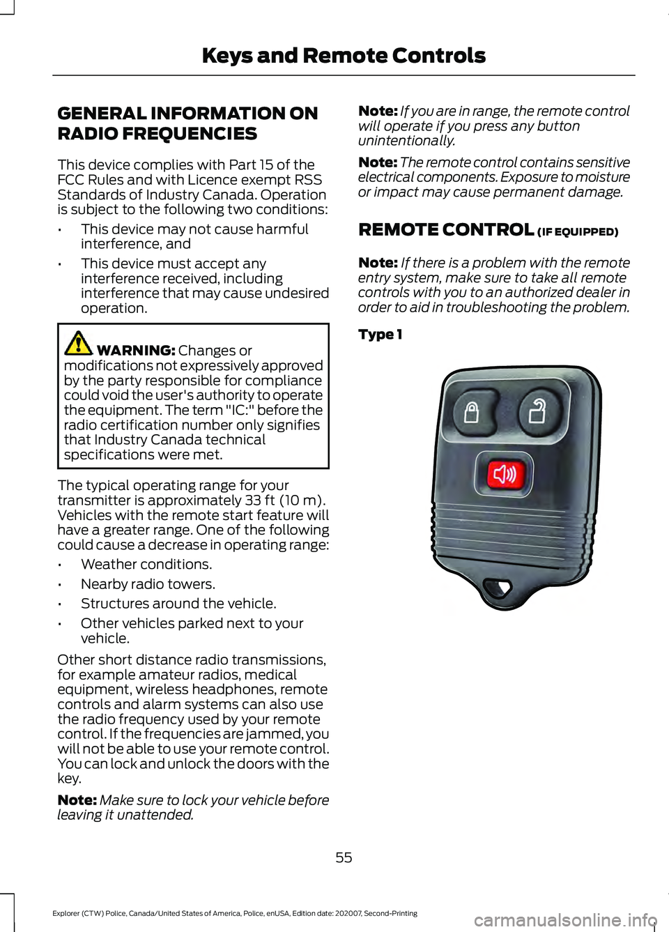
Type 1 55
Explorer (CTW) Police, Canada/United States of America, Police, enUSA, Edition date: 202007, Second-Printing Keys and Remote ControlsE203600
Page 59 of 412
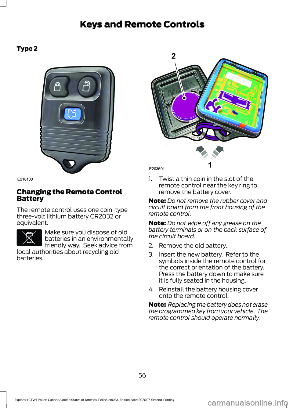
Type 2
Changing the Remote Control
Battery
The remote control uses one coin-type
three-volt lithium battery CR2032 or
equivalent.
Make sure you dispose of old
batteries in an environmentally
friendly way. Seek advice from
local authorities about recycling old
batteries. 1. Twist a thin coin in the slot of the
remote control near the key ring to
remove the battery cover.
Note: Do not remove the rubber cover and
circuit board from the front housing of the
remote control.
Note: Do not wipe off any grease on the
battery terminals or on the back surface of
the circuit board.
2. Remove the old battery.
3. Insert the new battery. Refer to the symbols inside the remote control for
the correct orientation of the battery.
Press the battery down to make sure
it is fully seated in the housing.
4. Reinstall the battery housing cover onto the remote control.
Note: Replacing the battery does not erase
the programmed key from your vehicle. The
remote control should operate normally.
56
Explorer (CTW) Police, Canada/United States of America, Police, enUSA, Edition date: 202007, Second-Printing Keys and Remote ControlsE218100 E107998 1E203601
2
Page 60 of 412
Sounding the Panic Alarm (If Equipped)
On Type 1, press the button to
sound the panic alarm. Press the
button again or switch the
ignition on to turn it off.
Note: The panic alarm operates regardless
of the ignition position.
Opening the Liftgate With the
Liftgate Button (If Equipped) On Type 2, press the button to
unlock the liftgate. The liftgate
unlocks for 45 seconds, during
which time you can open the liftgate using
the exterior liftgate release button. See
Manual Liftgate
(page 61).
Note: Only the liftgate unlocks. All other
passenger doors remain in the previous
locking state.
Note: If you do not open the liftgate within
45 seconds of unlocking it, the liftgate locks
again. Press the button on the remote
control or use the key blade inserted into
the liftgate lock cylinder to unlock the
liftgate again.
Note: The liftgate does not unlock when
you unlock all the doors using the remote
control or power door lock control, unless
you use the global unlock feature which,
overrides the 45-second timer.
REPLACING A LOST KEY OR
REMOTE CONTROL
Replacement keys or remote controls can
be purchased from an authorized dealer.
Authorized dealers can program remote
controls for your vehicle.
57
Explorer (CTW) Police, Canada/United States of America, Police, enUSA, Edition date: 202007, Second-Printing Keys and Remote ControlsE138624