auxiliary battery location FORD SIERRA 1983 1.G Body Electrical System Workshop Manual
[x] Cancel search | Manufacturer: FORD, Model Year: 1983, Model line: SIERRA, Model: FORD SIERRA 1983 1.GPages: 25, PDF Size: 1.7 MB
Page 3 of 25

5To find the source of an intermittent wiring
fault (usually due to a poor or dirty
connection, or damaged wiring insulation), an
integrity test can be performed on the wiring,
which involves moving the wiring by hand, to
see if the fault occurs as the wiring is moved.
It should be possible to narrow down the
source of the fault to a particular section of
wiring. This method of testing can be used in
conjunction with any of the tests described in
the following sub-Sections.
6Apart from problems due to poor
connections, two basic types of fault can
occur in an electrical circuit - open-circuit, or
short-circuit.
7Open-circuit faults are caused by a break
somewhere in the circuit, which prevents
current from flowing. An open-circuit fault will
prevent a component from working, but will
not cause the relevant circuit fuse to blow.
8Short-circuit faults are caused by a “short”
somewhere in the circuit, which allows the
current flowing in the circuit to “escape” along
an alternative route, usually to earth. Short-
circuit faults are normally caused by a
breakdown in wiring insulation, which allows a
feed wire to touch either another wire, or an
earthed component such as the bodyshell. A
short-circuit fault will normally cause the
relevant circuit fuse to blow.
Note: A short-circuit that occurs in the wiring
between a circuit’s battery supply and its fuse
will not cause the fuse in that particular circuit
to blow. This part of the circuit is unprotected
- bear this in mind when fault-finding on the
vehicle’s electrical system.
Finding an open-circuit
9To check for an open-circuit, connect one
lead of a circuit tester or voltmeter to either
the negative battery terminal or a known good
earth.
10Connect the other lead to a connector in
the circuit being tested, preferably nearest to
the battery or fuse.
11Switch on the circuit, bearing in mind that
some circuits are live only when the ignition
switch is moved to a particular position.
12If voltage is present (indicated either by
the tester bulb lighting or a voltmeter reading,
as applicable), this means that the section of
the circuit between the relevant connector
and the battery is problem-free.
13Continue to check the remainder of the
circuit in the same fashion.
14When a point is reached at which no
voltage is present, the problem must lie
between that point and the previous test point
with voltage. Most problems can be traced to
a broken, corroded or loose connection.
Finding a short-circuit
15To check for a short-circuit, first
disconnect the load(s) from the circuit (loads
are the components which draw current from
a circuit, such as bulbs, motors, heating
elements, etc).
16Remove the relevant fuse from the circuit,
and connect a circuit tester or voltmeter to the
fuse connections.17Switch on the circuit, bearing in mind that
some circuits are live only when the ignition
switch is moved to a particular position.
18If voltage is present (indicated either by
the tester bulb lighting or a voltmeter reading,
as applicable), this means that there is a
short-circuit.
19If no voltage is present, but the fuse still
blows with the load(s) connected, this
indicates an internal fault in the load(s).
Finding an earth fault
20The battery negative terminal is connected
to “earth” - the metal of the
engine/transmission and the car body - and
most systems are wired so that they only
receive a positive feed, the current returning via
the metal of the car body. This means that the
component mounting and the body form part
of that circuit. Loose or corroded mountings
can therefore cause a range of electrical faults,
ranging from total failure of a circuit, to a
puzzling partial fault. In particular, lights may
shine dimly (especially when another circuit
sharing the same earth point is in operation),
motors (eg wiper motors or the radiator cooling
fan motor) may run slowly, and the operation of
one circuit may have an apparently-unrelated
effect on another. Note that on many vehicles,
earth straps are used between certain
components, such as the engine/transmission
and the body, usually where there is no metal-
to-metal contact between components, due to
flexible rubber mountings, etc.
21To check whether a component is
properly earthed, disconnect the battery, and
connect one lead of an ohmmeter to a known
good earth point. Connect the other lead to
the wire or earth connection being tested. The
resistance reading should be zero; if not,
check the connection as follows.
22If an earth connection is thought to be
faulty, dismantle the connection, and clean
back to bare metal both the bodyshell and the
wire terminal, or the component’s earth
connection mating surface. Be careful to
remove all traces of dirt and corrosion, then
use a knife to trim away any paint, so that a
clean metal-to-metal joint is made. On
reassembly, tighten the joint fasteners
securely; if a wire terminal is being refitted,
use serrated washers between the terminaland the bodyshell, to ensure a clean and
secure connection. When the connection is
remade, prevent the onset of corrosion in the
future by applying a coat of petroleum jelly or
silicone-based grease, or by spraying on (at
regular intervals) a proprietary ignition sealer.Location
1The main fuses and relays are located in a
box in the engine compartment on the right-
hand side of the bulkhead. The circuits
protected are identified by symbols on the
underside of the fusebox cover. On certain
models, additional relays and fuses are located
in various positions beneath the facia panels. If
uncertain of the location of an auxiliary relay or
fuse, it is suggested that a Ford dealer is
consulted, as the relay and fuse locations vary
substantially depending on model.
Renewal
2Always renew a fuse with one of identical
rating and never renew it more than once
without finding the source of the trouble
(usually a short circuit). Always switch off the
ignition before renewing a fuse or relay, and
when renewing the wiper motor fuse keep the
hands clear of the wiper linkage as it may
return to the parked position. Note that the
fuses are colour-coded as follows:
10ARed
15ABlue
20AYellow
25ANatural
10AGreen
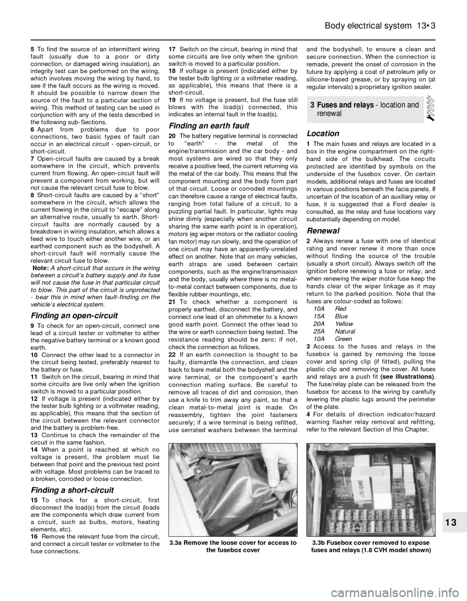
3Access to the fuses and relays in the
fusebox is gained by removing the loose
cover and spring clip (if fitted), pulling the
plastic clip and removing the cover. All fuses
and relays are a push fit (see illustrations).
The fuse/relay plate can be released from the
fusebox for access to the wiring by carefully
levering the plastic lugs around the perimeter
of the plate.
4For details of direction indicator/hazard
warning flasher relay removal and refitting,
refer to the relevant Section of this Chapter.
3Fuses and relays - location and
renewal
Body electrical system 13•3
13
3.3b Fusebox cover removed to expose
fuses and relays (1.8 CVH model shown)3.3a Remove the loose cover for access to
the fusebox cover
Page 9 of 25

Location
1The AWS control unit, and (when fitted) the
bulb failure monitor, are located behind the
glovebox on models up to 1987.
2On models from 1987, the control and bulb
failure modules are located behind the driver’s
side footwell trim panel.
Testing
3Thorough testing and fault finding should
be left to a Ford dealer or other electrical
specialist, having test equipment. Unskilled or
uninformed testing may cause damage.
4Investigation of malfunctions should begin
by checking that all wiring is intact and
securely connected. If checking wires or
sensors for continuity, always disconnect the
control unit and/or bulb failure monitor before
so doing, otherwise damage may be caused.
5Note that false oil level readings can result if
the car is parked on a slope. False bulb failure
warnings may occur if incorrect wattage bulbs
are fitted.
Removal and refitting
6Disconnect the battery negative lead.
Warning lamp bulbs
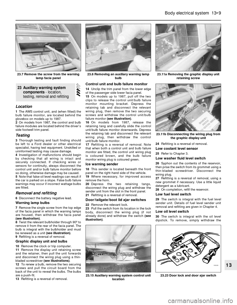
7Remove the single screw from the top edge
of the facia panel in which the warning lamps
are housed, then withdraw the facia panel
(see illustration).
8Twist the relevant bulbholder through 90º to
remove it from the rear of the facia panel. The
bulb is integral with the bulbholder and must
be renewed as a unit (see illustration).
9Refitting is a reversal of removal.
Graphic display unit and bulbs
10Remove the clock or trip computer.
11Remove the display unit retaining screw
and the retainer, then pull the unit forwards
and disconnect the wiring plug using a thin-
bladed screwdriver (see illustrations).
12To renew a bulb, remove the two securing
screws and pull the circuit board from the
back of the unit to reveal the bulbs. The bulbs
are a push-fit.
13Refitting is a reversal of removal.
Control unit and bulb failure monitor
14Unclip the trim panel from the lower edge
of the passenger side lower facia panel.
15On models up to 1987, pull off the two
clips to release the control unit/bulb failure
monitor mounting bracket. Depress the
retaining tab and disconnect the relevant
wiring plug, then remove the two securing
screws and withdraw the control unit/bulb
failure monitor (see illustration).
16On models from 1987, release the
retaining tang and carefully slide the control
unit/bulb failure monitor downwards. Depress
the retaining tab and disconnect the relevant
wiring plug, then withdraw the control
unit/bulb failure monitor.
17Refitting is a reversal of removal. Note
that when both a control unit and bulb failure
monitor are fitted, the control unit wiring plug
is coloured brown, and the bulb failure
monitor wiring plug is coloured green.
Ice warning sender
18This sender is located beneath the front
panel on the right-hand side of the vehicle.
19Where necessary, for improved access
remove the horn.
20Depress the two retaining tangs,
disconnect the wiring plug and withdraw the
sender unit from the slot in the front panel.
21Refitting is a reversal of removal.
Door/tailgate/boot lid ajar switches
22Remove the relevant lock.
23Pull the switch from its location in the lock
body, disconnect the wiring plug (if not
already done) and withdraw the switch (see
illustration).24Refitting is a reversal of removal.
Low coolant level sensor
25Refer to Chapter 3.
Low washer fluid level switch
26Syphon out the contents of the reservoir,
then prise the switch from its grommet using a
thin-bladed screwdriver. Disconnect the
wiring plug.
27Refitting is a reversal of removal, using a
new grommet if necessary. Use a little liquid
detergent as a lubricant.
28On completion, refill the reservoir.
Low fuel level switch
29The switch is integral with the fuel level
sender unit. Details of fuel level sender unit
removal and refitting are given in Chapter 4.
Low oil level switch
30The switch is integral with the oil level
dipstick. To remove, simply withdraw the
23Auxiliary warning system
components - location,
testing, removal and refitting
Body electrical system 13•9
13
23.11a Removing the graphic display unit
retaining screw
23.23 Door lock and door ajar switch23.15 Auxiliary warning system control unit
location
23.11b Disconnecting the wiring plug from
the graphic display unit
23.8 Removing an auxiliary warning lamp
bulb23.7 Remove the screw from the warning
lamp facia panel
Page 16 of 25

Models from 1987
5Remove the two securing screws, then
withdraw the lamp forwards and disconnect
the two wiring plugs.
6Refitting is a reversal of removal, but where
necessary use a new gasket between the
lamp and bumper.
7On completion, the vertical alignment of the
foglamp must be adjusted. For the foglamps,
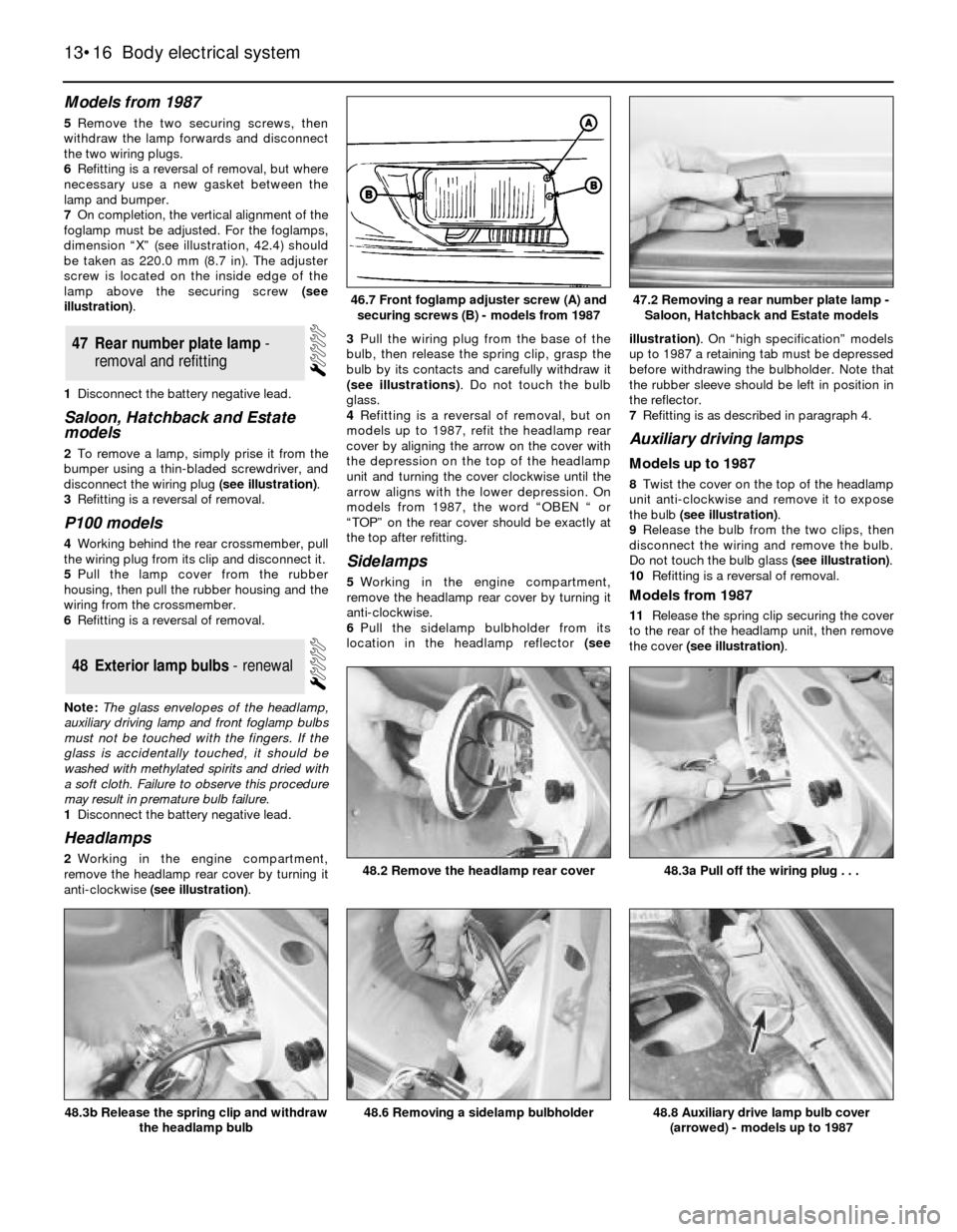
dimension “X” (see illustration, 42.4) should
be taken as 220.0 mm (8.7 in). The adjuster
screw is located on the inside edge of the
lamp above the securing screw (see
illustration).
1Disconnect the battery negative lead.
Saloon, Hatchback and Estate
models
2To remove a lamp, simply prise it from the
bumper using a thin-bladed screwdriver, and
disconnect the wiring plug (see illustration).
3Refitting is a reversal of removal.
P100 models
4Working behind the rear crossmember, pull
the wiring plug from its clip and disconnect it.
5Pull the lamp cover from the rubber
housing, then pull the rubber housing and the
wiring from the crossmember.
6Refitting is a reversal of removal.
Note: The glass envelopes of the headlamp,
auxiliary driving lamp and front foglamp bulbs
must not be touched with the fingers. If the
glass is accidentally touched, it should be
washed with methylated spirits and dried with
a soft cloth. Failure to observe this procedure
may result in premature bulb failure.
1Disconnect the battery negative lead.
Headlamps
2Working in the engine compartment,
remove the headlamp rear cover by turning it
anti-clockwise (see illustration).3Pull the wiring plug from the base of the
bulb, then release the spring clip, grasp the
bulb by its contacts and carefully withdraw it
(see illustrations). Do not touch the bulb
glass.
4Refitting is a reversal of removal, but on
models up to 1987, refit the headlamp rear
cover by aligning the arrow on the cover with
the depression on the top of the headlamp
unit and turning the cover clockwise until the
arrow aligns with the lower depression. On
models from 1987, the word “OBEN “ or
“TOP” on the rear cover should be exactly at
the top after refitting.
Sidelamps
5Working in the engine compartment,
remove the headlamp rear cover by turning it
anti-clockwise.
6Pull the sidelamp bulbholder from its
location in the headlamp reflector (seeillustration). On “high specification” models
up to 1987 a retaining tab must be depressed
before withdrawing the bulbholder. Note that
the rubber sleeve should be left in position in
the reflector.
7Refitting is as described in paragraph 4.
Auxiliary driving lamps
Models up to 1987
8Twist the cover on the top of the headlamp
unit anti-clockwise and remove it to expose
the bulb (see illustration).
9Release the bulb from the two clips, then
disconnect the wiring and remove the bulb.
Do not touch the bulb glass (see illustration).
10Refitting is a reversal of removal.
Models from 1987
11Release the spring clip securing the cover
to the rear of the headlamp unit, then remove
the cover (see illustration).
48Exterior lamp bulbs - renewal
47Rear number plate lamp -
removal and refitting
13•16Body electrical system
46.7 Front foglamp adjuster screw (A) and
securing screws (B) - models from 1987
48.2 Remove the headlamp rear cover
48.8 Auxiliary drive lamp bulb cover
(arrowed) - models up to 198748.6 Removing a sidelamp bulbholder48.3b Release the spring clip and withdraw
the headlamp bulb
48.3a Pull off the wiring plug . . .
47.2 Removing a rear number plate lamp -
Saloon, Hatchback and Estate models