jacking FORD SIERRA 1993 2.G Engine Electrical Systems Workshop Manual
[x] Cancel search | Manufacturer: FORD, Model Year: 1993, Model line: SIERRA, Model: FORD SIERRA 1993 2.GPages: 24, PDF Size: 0.93 MB
Page 8 of 24

Mitsubishi type
21Unscrew the pulley nut. To prevent the
shaft rotating, insert an Allen key in the end of
the shaft.
22Remove the spring washer, pulley, fan,
spacer and dust shield.
23Scribe an alignment mark along the length
of the alternator to facilitate reassembly of the
drive end housing, stator and rear housing.
24Unscrew the through-bolts and withdraw
the drive end housing from the rotor shaft.
25Remove the seal and spacer from the
rotor shaft.
26Remove the rotor from the rear housing
and the stator. This may require the
application of local heat to the rear housing
using a large soldering iron. Do not use a heat
gun, as this may result in damage to the
diodes.
27Unscrew the four securing bolts and
withdraw the diode pack stator assembly
from the rear housing.
28Unsolder the stator leads from the diode
pack terminals. Use a pair of pliers when
unsoldering to act as a heat sink, otherwise
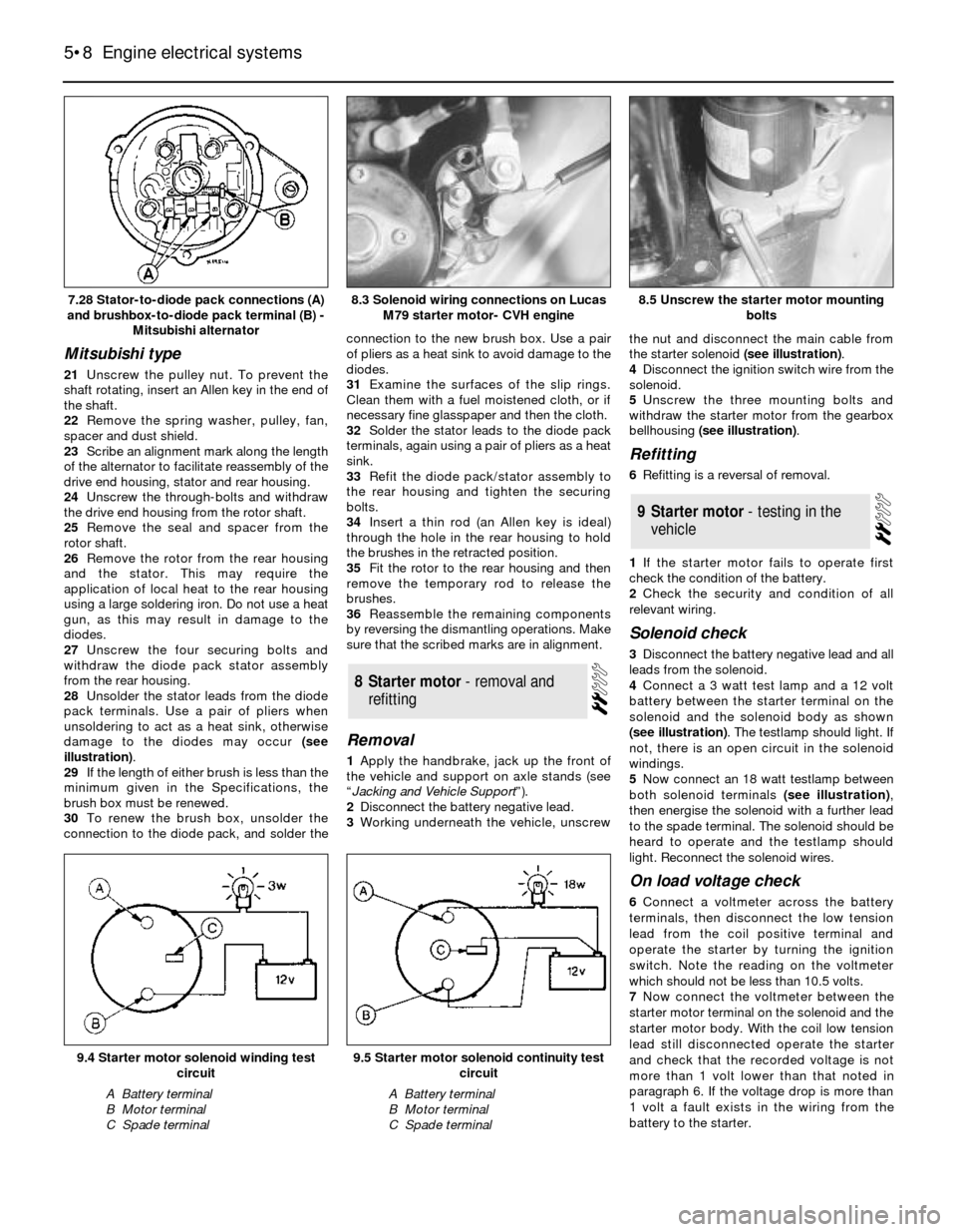
damage to the diodes may occur (see
illustration).
29If the length of either brush is less than the
minimum given in the Specifications, the
brush box must be renewed.
30To renew the brush box, unsolder the
connection to the diode pack, and solder theconnection to the new brush box. Use a pair
of pliers as a heat sink to avoid damage to the
diodes.
31Examine the surfaces of the slip rings.
Clean them with a fuel moistened cloth, or if
necessary fine glasspaper and then the cloth.
32Solder the stator leads to the diode pack
terminals, again using a pair of pliers as a heat
sink.
33Refit the diode pack/stator assembly to
the rear housing and tighten the securing
bolts.
34Insert a thin rod (an Allen key is ideal)
through the hole in the rear housing to hold
the brushes in the retracted position.
35Fit the rotor to the rear housing and then
remove the temporary rod to release the
brushes.
36Reassemble the remaining components
by reversing the dismantling operations. Make
sure that the scribed marks are in alignment.
Removal
1Apply the handbrake, jack up the front of
the vehicle and support on axle stands (see
“Jacking and Vehicle Support”).
2Disconnect the battery negative lead.
3Working underneath the vehicle, unscrewthe nut and disconnect the main cable from
the starter solenoid (see illustration).
4Disconnect the ignition switch wire from the
solenoid.
5Unscrew the three mounting bolts and
withdraw the starter motor from the gearbox
bellhousing (see illustration).
Refitting
6Refitting is a reversal of removal.
1If the starter motor fails to operate first
check the condition of the battery.
2Check the security and condition of all
relevant wiring.
Solenoid check
3Disconnect the battery negative lead and all
leads from the solenoid.
4Connect a 3 watt test lamp and a 12 volt
battery between the starter terminal on the
solenoid and the solenoid body as shown
(see illustration). The testlamp should light. If
not, there is an open circuit in the solenoid
windings.
5Now connect an 18 watt testlamp between
both solenoid terminals (see illustration),
then energise the solenoid with a further lead
to the spade terminal. The solenoid should be
heard to operate and the testlamp should
light. Reconnect the solenoid wires.
On load voltage check
6Connect a voltmeter across the battery
terminals, then disconnect the low tension
lead from the coil positive terminal and
operate the starter by turning the ignition
switch. Note the reading on the voltmeter
which should not be less than 10.5 volts.
7Now connect the voltmeter between the
starter motor terminal on the solenoid and the
starter motor body. With the coil low tension
lead still disconnected operate the starter
and check that the recorded voltage is not
more than 1 volt lower than that noted in
paragraph 6. If the voltage drop is more than
1 volt a fault exists in the wiring from the
battery to the starter.
9Starter motor - testing in the
vehicle
8Starter motor - removal and
refitting
5•8Engine electrical systems
7.28 Stator-to-diode pack connections (A)
and brushbox-to-diode pack terminal (B) -
Mitsubishi alternator8.5 Unscrew the starter motor mounting
bolts
9.5 Starter motor solenoid continuity test
circuit
A Battery terminal
B Motor terminal
C Spade terminal
9.4 Starter motor solenoid winding test
circuit
A Battery terminal
B Motor terminal
C Spade terminal
8.3 Solenoid wiring connections on Lucas
M79 starter motor- CVH engine
Page 21 of 24

3Partially drain the cooling system. There is no
need to remove the cylinder block drain plug.
4Disconnect the sensor wiring plug by
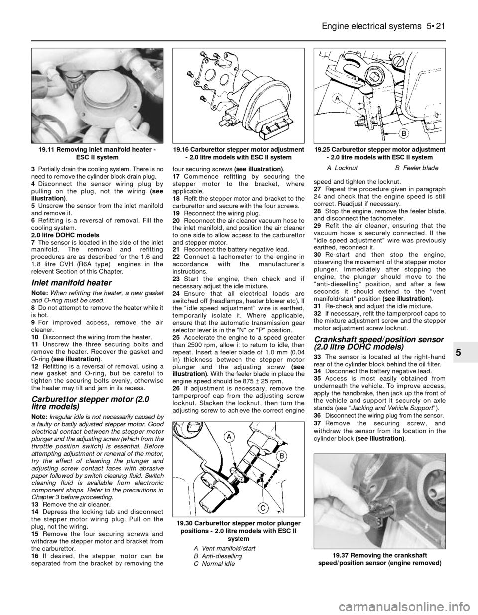
pulling on the plug, not the wiring (see
illustration).
5Unscrew the sensor from the inlet manifold
and remove it.
6Refitting is a reversal of removal. Fill the
cooling system.
2.0 litre DOHC models
7The sensor is located in the side of the inlet
manifold. The removal and refitting
procedures are as described for the 1.6 and
1.8 litre CVH (R6A type) engines in the
relevent Section of this Chapter.
Inlet manifold heater
Note: When refitting the heater, a new gasket
and O-ring must be used.
8Do not attempt to remove the heater while it
is hot.
9For improved access, remove the air
cleaner.
10Disconnect the wiring from the heater.
11Unscrew the three securing bolts and
remove the heater. Recover the gasket and
O-ring (see illustration).
12Refitting is a reversal of removal, using a
new gasket and O-ring, but be careful to
tighten the securing bolts evenly, otherwise
the heater may tilt and jam in its recess.
Carburettor stepper motor (2.0
litre models)
Note: Irregular idle is not necessarily caused by
a faulty or badly adjusted stepper motor. Good
electrical contact between the stepper motor
plunger and the adjusting screw (which from the
throttle position switch) is essential. Before
attempting adjustment or renewal of the motor,
try the effect of cleaning the plunger and
adjusting screw contact faces with abrasive
paper followed by switch cleaning fluid. Switch
cleaning fluid is available from electronic
component shops. Refer to the precautions in
Chapter 3 before proceeding.
13Remove the air cleaner.
14Depress the locking tab and disconnect
the stepper motor wiring plug. Pull on the
plug, not the wiring.
15Remove the four securing screws and
withdraw the stepper motor and bracket from
the carburettor.
16If desired, the stepper motor can be
separated from the bracket by removing thefour securing screws (see illustration).
17Commence refitting by securing the
stepper motor to the bracket, where
applicable.
18Refit the stepper motor and bracket to the
carburettor and secure with the four screws.
19Reconnect the wiring plug.
20Reconnect the air cleaner vacuum hose to
the inlet manifold, and position the air cleaner
to one side to allow access to the carburettor
and stepper motor.
21Reconnect the battery negative lead.
22Connect a tachometer to the engine in
accordance with the manufacturer’s
instructions.
23Start the engine, then check and if
necessary adjust the idle mixture.
24Ensure that all electrical loads are
switched off (headlamps, heater blower etc). If
the “idle speed adjustment” wire is earthed,
temporarily isolate it. Where applicable,
ensure that the automatic transmission gear
selector lever is in the “N” or “P” position.
25Accelerate the engine to a speed greater
than 2500 rpm, allow it to return to idle, then
repeat. Insert a feeler blade of 1.0 mm (0.04
in) thickness between the stepper motor
plunger and the adjusting screw (see
illustration). With the feeler blade in place the
engine speed should be 875 ±25 rpm.
26If adjustment is necessary, remove the
tamperproof cap from the adjusting screw
locknut. Slacken the locknut, then turn the
adjusting screw to achieve the correct enginespeed and tighten the locknut.
27Repeat the procedure given in paragraph
24 and check that the engine speed is still
correct. Readjust if necessary.
28Stop the engine, remove the feeler blade,
and disconnect the tachometer.
29Refit the air cleaner, ensuring that the
vacuum hose is securely connected. If the
“idle speed adjustment” wire was previously
earthed, reconnect it.
30Re-start and then stop the engine,
observing the movement of the stepper motor
plunger. Immediately after stopping the
engine, the plunger should move to the
“anti-dieselling” position, and after a few
seconds it should extend to the “vent
manifold/start” position (see illustration).
31Re-check and adjust the idle mixture.
32If necessary, refit the tamperproof caps to
the mixture adjustment screw and the stepper
motor adjustment screw locknut.
Crankshaft speed/position sensor
(2.0 litre DOHC models)
33The sensor is located at the right-hand
rear of the cylinder block behind the oil filter.
34Disconnect the battery negative lead.
35Access is most easily obtained from
underneath the vehicle. To improve access,
apply the handbrake, then jack up the front of
the vehicle and support it securely on axle
stands (see “Jacking and Vehicle Support”).
36Disconnect the wiring plug from the sensor.
37Remove the securing screw, and
withdraw the sensor from its location in the
cylinder block (see illustration).
Engine electrical systems 5•21
5
19.25 Carburettor stepper motor adjustment
- 2.0 litre models with ESC II system
A LocknutB Feeler blade
19.37 Removing the crankshaft
speed/position sensor (engine removed)
19.30 Carburettor stepper motor plunger
positions - 2.0 litre models with ESC II
system
A Vent manifold/start
B Anti-dieselling
C Normal idle
19.16 Carburettor stepper motor adjustment
- 2.0 litre models with ESC II system19.11 Removing inlet manifold heater -
ESC II system
Page 24 of 24

Vehicle speed sensor
1.6 and 1.8 litre CVH (R6A type) and
2.0 litre DOHC fuel injection models
27The sensor is located in the left-hand side
of the gearbox/transmission.
28Disconnect the battery negative lead.
29Jack up the vehicle and support it
securely on axle stands (see “Jacking and
Vehicle Support”).
30Detach the sensor wiring connector from
its bracket, and separate the two halves of the
connector.
31Unscrew the securing bolt, and withdraw
the wiring connector bracket, noting its
orientation.
32Withdraw the sensor from the
gearbox/transmission casing (see
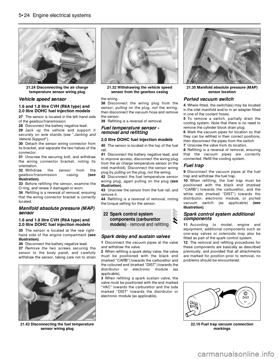
illustration).
33Before refitting the sensor, examine the
O-ring, and renew if damaged or worn.
34Refitting is a reversal of removal, ensuring
that the wiring connector bracket is correctly
located.
Manifold absolute pressure (MAP)
sensor
1.6 and 1.8 litre CVH (R6A type) and
2.0 litre DOHC fuel injection models
35The sensor is located at the rear right-
hand side of the engine compartment (see
illustration).
36Disconnect the battery negative lead.
37Remove the two screws securing the
sensor to the body panel, and carefully
withdraw the sensor, taking care not to strainthe wiring.
38Disconnect the wiring plug from the
sensor, pulling on the plug, not the wiring,
then disconnect the vacuum hose and remove
the sensor.
39Refitting is a reversal of removal.
Fuel temperature sensor -
removal and refitting
2.0 litre DOHC fuel injection models
40The sensor is located in the top of the fuel
rail.
41Disconnect the battery negative lead, and
to improve access, disconnect the wiring plug
from the air charge temperature sensor (in the
inlet manifold). Disconnect the sensor wiring
plug by pulling on the plug, not the wiring.
42Disconnect the fuel temperature sensor
wiring plug, again pulling on the plug (see
illustration).
43Unscrew the sensor from the fuel rail, and
remove it.
44Refitting is a reversal of removal, noting
the torque setting for the sensor.
Spark delay and sustain valves
1Disconnect the vacuum pipes at the valve
and withdraw the valve.
2When refitting a spark delay valve, the valve
must be positioned with the black end
(marked “CARB”) towards the carburettor and
the coloured end (marked “DIST”) towards the
distributor or electronic module (as
applicable).
3When refitting a spark sustain valve, the
valve must be positioned with the end marked
“VAC” towards the carburettor and the side
marked “DIST” towards the distributor or
electronic module (as applicable).
Ported vacuum switch
4Where fitted, the switch(es) may be located
in the inlet manifold and/or in an adapter fitted
in one of the coolant hoses.
5To remove a switch, partially drain the
cooling system. Note that there is no need to
remove the cylinder block drain plug.
6Mark the vacuum pipes for location so that
they can be refitted in their correct positions,
then disconnect the pipes from the switch.
7Unscrew the valve from its location.
8Refitting is a reversal of removal, ensuring
that the vacuum pipes are correctly
connected. Refill the cooling system.
Fuel trap
9Disconnect the vacuum pipes at the fuel
trap and withdraw the fuel trap.
10When refitting, the fuel trap must be
positioned with the black end (marked
“CARB”) towards the carburettor, and the
white side (marked “DIST”) towards the
distributor, electronic module, or ported
vacuum switch (as applicable) (see
illustration).
Spark control system additional
components
11According to model, engine and
equipment, additional components such as
one-way valves or solenoids may also be
fitted as part of the spark control system.
12The removal and refitting procedures for
these components are basically as described
previously, and provided that all attachments
are marked for position prior to removal, no
problems should be encountered.
22Spark control system
components (carburettor
models) - removal and refitting
5•24Engine electrical systems
21.24 Disconnecting the air charge
temperature sensor wiring plug21.35 Manifold absolute pressure (MAP)
sensor location
22.10 Fuel trap vacuum connection
markings21.42 Disconnecting the fuel temperature
sensor wiring plug
21.32 Withdrawing the vehicle speed
sensor from the gearbox casing