display FORD TRANSIT CONNECT 2020 Owners Manual
[x] Cancel search | Manufacturer: FORD, Model Year: 2020, Model line: TRANSIT CONNECT, Model: FORD TRANSIT CONNECT 2020Pages: 509, PDF Size: 7.73 MB
Page 230 of 509
Switching Distance Indication On or Off
To switch distance indication on or off, use the information display controls on
the steering wheel to select the following:
Action
Menu Item
Press the menu button.
Driver Assist.
Press the OK button.
Pre-Collision Assist
Press the
OK button.
Distance Indication
Pre-Collision Assist System
Sensors
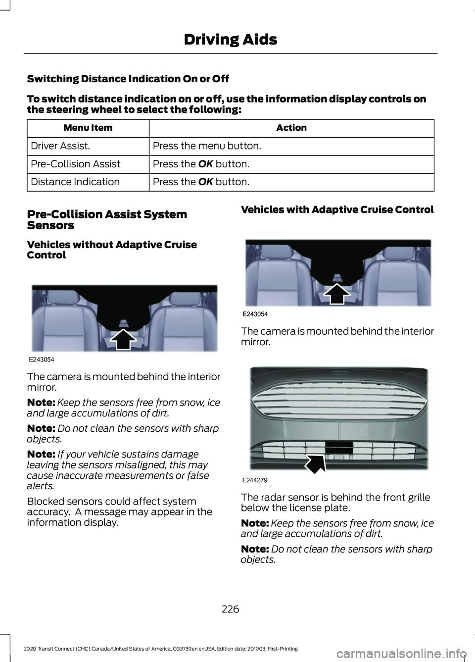
Vehicles without Adaptive Cruise
Control The camera is mounted behind the interior
mirror.
Note:
Keep the sensors free from snow, ice
and large accumulations of dirt.
Note: Do not clean the sensors with sharp
objects.
Note: If your vehicle sustains damage
leaving the sensors misaligned, this may
cause inaccurate measurements or false
alerts.
Blocked sensors could affect system
accuracy. A message may appear in the
information display. Vehicles with Adaptive Cruise Control
The camera is mounted behind the interior
mirror.
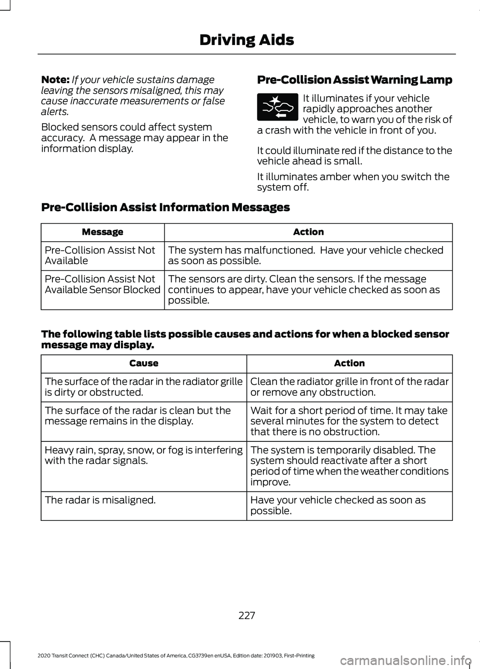
The radar sensor is behind the front grille
below the license plate.
Note:
Keep the sensors free from snow, ice
and large accumulations of dirt.
Note: Do not clean the sensors with sharp
objects.
226
2020 Transit Connect (CHC) Canada/United States of America, CG3739en enUSA, Edition date: 201903, First-Printing Driving AidsE243054 E243054 E244279
Page 231 of 509
Note:
If your vehicle sustains damage
leaving the sensors misaligned, this may
cause inaccurate measurements or false
alerts.
Blocked sensors could affect system
accuracy. A message may appear in the
information display. Pre-Collision Assist Warning Lamp It illuminates if your vehicle
rapidly approaches another
vehicle, to warn you of the risk of
a crash with the vehicle in front of you.
It could illuminate red if the distance to the
vehicle ahead is small.
It illuminates amber when you switch the
system off.
Pre-Collision Assist Information Messages Action
Message
The system has malfunctioned. Have your vehicle checked
as soon as possible.
Pre-Collision Assist Not
Available
The sensors are dirty. Clean the sensors. If the message
continues to appear, have your vehicle checked as soon as
possible.
Pre-Collision Assist Not
Available Sensor Blocked
The following table lists possible causes and actions for when a blocked sensor
message may display. Action
Cause
Clean the radiator grille in front of the radar
or remove any obstruction.
The surface of the radar in the radiator grille
is dirty or obstructed.
Wait for a short period of time. It may take
several minutes for the system to detect
that there is no obstruction.
The surface of the radar is clean but the
message remains in the display.
The system is temporarily disabled. The
system should reactivate after a short
period of time when the weather conditions
improve.
Heavy rain, spray, snow, or fog is interfering
with the radar signals.
Have your vehicle checked as soon as
possible.
The radar is misaligned.
227
2020 Transit Connect (CHC) Canada/United States of America, CG3739en enUSA, Edition date: 201903, First-Printing Driving Aids
Page 232 of 509
Action
Cause
Clean the outside of the windshield in front
of the camera.
The windshield in front of the camera is
dirty or obstructed.
Wait for a short period of time. It may take
several minutes for the camera to detect
that there is no obstruction.
The windshield in front of the camera is
clean but the message remains in the
display.
Wait for a short period of time. The
message should clear when the temper-
ature around the camera decreases.
Excessive heat around the camera.
228
2020 Transit Connect (CHC) Canada/United States of America, CG3739en enUSA, Edition date: 201903, First-Printing Driving Aids
Page 243 of 509
RV & Trailer Towing Guide Online
http://www.fleet.ford.com/towing-guides/
Website
TRAILER SWAY CONTROL
If the trailer begins to sway the stability
control warning lamp flashes in the
information display. The system applies
the brakes to the individual wheels and
reduces engine torque to aid vehicle
stability.
Stop your vehicle as soon as it is safe to
do so. Check the vertical weight on the tow
ball and trailer load distribution. See
Capacities and Specifications (page
337). See Load Carrying (page 229).
Note: This feature does not prevent trailer
sway, but reduces it once it begins.
Note: This feature cannot stop all trailers
from swaying.
Note: In some cases, if your vehicle speed
is too high, the system may turn on multiple
times, gradually reducing your vehicle speed.
RECOMMENDED TOWING
WEIGHTS
Your vehicle may tow a trailer. The
maximum loaded trailer weight
must be less than or equal to the
maximum loaded trailer weight
listed for your vehicle
configuration on the following
chart.
Do not exceed the maximum
loaded trailer weight for your
vehicle configuration listed in the
chart below. Note:
Make sure you take the
trailer frontal area into
consideration, do not exceed 20
feet² (1.86 meters²). Towing a
trailer that exceeds this frontal area
reduces the performance and fuel
economy of your vehicle when
towing. Select a trailer that has a
rounded front and an aerodynamic
design.
Note: For high altitude operation,
reduce the gross combined weight
by 2% per 1,000 ft (300 m)
starting at the 1,000 ft (300 m)
elevation point.
Note: Certain states require
electric trailer brakes for trailers
over a specified weight. Be sure to
check state regulations for this
specified weight. The maximum
loaded trailer weights listed may
be limited to this specified weight,
as the vehicle ’s electrical system
may not include the wiring
connector needed to activate
electric trailer brakes.
239
2020 Transit Connect (CHC) Canada/United States of America, CG3739en enUSA, Edition date: 201903, First-Printing Towing
Page 272 of 509
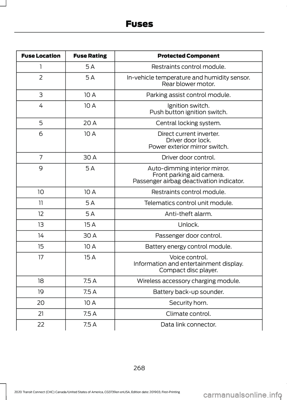
Protected Component
Fuse Rating
Fuse Location
Restraints control module.
5 A
1
In-vehicle temperature and humidity sensor.
5 A
2
Rear blower motor.
Parking assist control module.
10 A
3
Ignition switch.
10 A
4
Push button ignition switch.
Central locking system.
20 A
5
Direct current inverter.
10 A
6
Driver door lock.
Power exterior mirror switch.
Driver door control.
30 A
7
Auto-dimming interior mirror.
5 A
9
Front parking aid camera.
Passenger airbag deactivation indicator.
Restraints control module.
10 A
10
Telematics control unit module.
5 A
11
Anti-theft alarm.
5 A
12
Unlock.
15 A
13
Passenger door control.
30 A
14
Battery energy control module.
10 A
15
Voice control.
15 A
17
Information and entertainment display.Compact disc player.
Wireless accessory charging module.
7.5 A
18
Battery back-up sounder.
7.5 A
19
Security horn.
10 A
20
Climate control.
7.5 A
21
Data link connector.
7.5 A
22
268
2020 Transit Connect (CHC) Canada/United States of America, CG3739en enUSA, Edition date: 201903, First-Printing Fuses
Page 285 of 509
A warning lamp illuminates and
a message may appear in the
information display.
If the engine reaches a preset
over-temperature condition, the engine
automatically switches to alternating
cylinder operation. Each disabled cylinder
acts as an air pump and cools the engine.
When this occurs, your vehicle still
operates, however:
• Engine power is limited.
• The air conditioning system turns off.
Continued operation increases the engine
temperature, causing the engine to
completely shut down. Your steering and
braking effort increases in this situation.
When the engine temperature cools, you
can re-start the engine. Have your vehicle
checked as soon as possible to minimize
engine damage.
When Fail-Safe Mode Is Activated WARNING: Fail-safe mode is for
use during emergencies only. Operate
your vehicle in fail-safe mode only as
long as necessary to bring your vehicle
to rest in a safe location and seek
immediate repairs. When in fail-safe
mode, your vehicle will have limited
power, will not be able to maintain
high-speed operation, and may
completely shut down without warning,
potentially losing engine power, power
steering assist, and power brake assist,
which may increase the possibility of a
crash resulting in serious injury. WARNING:
Do not remove the
coolant reservoir cap when the engine is
on or the cooling system is hot. Wait 10
minutes for the cooling system to cool
down. Cover the coolant reservoir cap
with a thick cloth to prevent the
possibility of scalding and slowly remove
the cap. Failure to follow this instruction
could result in personal injury.
Your vehicle has limited engine power
when in the fail-safe mode, drive your
vehicle with caution. Your vehicle does not
maintain high-speed operation and the
engine may operate poorly.
Remember that the engine is capable of
automatically shutting down to prevent
engine damage. In this situation:
1. Pull off the road as soon as safely possible and switch the engine off.
2. If you are a member of a roadside assistance program, we recommend
that you contact your roadside
assistance service provider.
3. If this is not possible, wait for a short period of time for the engine to cool.
4. Check the coolant level. If the coolant level is at or below the minimum mark,
add prediluted coolant immediately.
5. When the engine temperature cools, you can re-start the engine. Have your
vehicle checked as soon as possible to
minimize engine damage.
Note: Driving your vehicle without repair
increases the chance of engine damage.
281
2020 Transit Connect (CHC) Canada/United States of America, CG3739en enUSA, Edition date: 201903, First-Printing Maintenance
Page 286 of 509
Engine Coolant Temperature
Management (If Equipped)
WARNING:
To reduce the risk of
crash and injury, be prepared that the
vehicle speed may reduce and the
vehicle may not be able to accelerate
with full power until the coolant
temperature reduces.
If you tow a trailer with your vehicle, the
engine may temporarily reach a higher
temperature during severe operating
conditions, for example ascending a long
or steep grade in high ambient
temperatures.
At this time, you may notice the coolant
temperature gauge moves toward the red
zone and a message may appear in the
information display.
You may notice a reduction in vehicle
speed caused by reduced engine power in
order to manage the engine coolant
temperature. Your vehicle may enter this
mode if certain high-temperature and
high-load conditions take place. The
amount of speed reduction depends on
vehicle loading, grade and ambient
temperature. If this occurs, there is no
need to stop your vehicle. You can
continue to drive.
The air conditioning may automatically
turn on and off during severe operating
conditions to protect the engine from
overheating. When the coolant
temperature decreases to the normal
operating temperature, the air conditioning
turns on.
If the coolant temperature gauge moves
fully into the red zone, or if the coolant
temperature warning or service engine
soon messages appear in your information
display, do the following: 1. Stop your vehicle as soon as it is safe
to do so. Fully apply the parking brake,
shift into park (P) or neutral (N).
2. Leave the engine running until the coolant temperature gauge needle
returns to the normal position. If the
temperature does not drop after
several minutes, follow the remaining
steps.
3. Switch the engine off and wait for it to
cool. Check the coolant level.
4. If the coolant level is at or below the minimum mark, add prediluted coolant
immediately.
5. If the coolant level is normal, restart the engine and continue.
AUTOMATIC TRANSMISSION
FLUID CHECK
The automatic transmission does not have
a transmission fluid dipstick.
Have an authorized dealer check and
change the transmission fluid at the
correct service interval. See
Scheduled
Maintenance (page 428). Your
transmission does not consume fluid.
However, if the transmission slips, shifts
slowly or if you notice a sign of leaking
fluid, contact an authorized dealer.
Do not use supplemental transmission
fluid additives, treatments or cleaning
agents. The use of these materials may
affect transmission operation and result
in damage to internal transmission
components.
282
2020 Transit Connect (CHC) Canada/United States of America, CG3739en enUSA, Edition date: 201903, First-Printing Maintenance
Page 304 of 509
Leather Interior (If Equipped)
Note: Follow the same procedure as
cleaning leather seats for cleaning leather
instrument panels and leather interior trim
surfaces.
For routine cleaning, wipe the surface with
a soft, damp cloth and a mild soap and
water solution. Dry the area with a clean,
soft cloth.
For cleaning and removing stains such as
dye transfer, use a leather cleaning product
for automotive interiors.
Do not use the following products as these
may damage the leather:
• Oil and petroleum or silicone-based
leather conditioners.
• Household cleaners.
• Alcohol solutions.
• Solvents or cleaners intended
specifically for rubber, vinyl and
plastics.
Suede Micro Fiber Fabric
(If Equipped)
Note: Do not steam clean.
Note: To avoid spots or discoloration, clean
the entire surface.
Do not use the following products:
• Leather care products.
• Household cleaners.
• Alcoholic solutions.
• Spot removers.
• Shoe polish. To clean:
•
Remove dust and loose dirt with a
vacuum cleaner.
• Wipe the surface with a soft, damp
cloth and a mild soap and water
solution. Dry the area with a clean, soft
cloth.
• If a ring forms on the fabric after spot
cleaning, clean the entire area
immediately, but do not soak or the
ring will set.
Instrument Cluster Screens, LCD
Screens and Radio Screens
Note: Do not use abrasives, alcoholic
solvents or chemical solvents to clean the
instrument cluster screens, LCD screens or
radio screens. These cleaning products can
damage the screens.
Clean the instrument panel and cluster
lens with a clean, damp and soft cloth,
then use a clean, dry and soft cloth to dry
these areas.
Do not spray any liquid directly onto the
screens.
Do not use a microfiber cloth to clean the
bezel around the display screens as it could
damage the surface.
Rear Windows
Note: Do not use any abrasive materials to
clean the interior of the rear windows.
Note: Do not install stickers or labels to the
interior of the rear windows.
Mirrors
Do not clean the housing or glass of any
mirror with harsh abrasives, fuel or other
petroleum or ammonia-based cleaning
products.
300
2020 Transit Connect (CHC) Canada/United States of America, CG3739en enUSA, Edition date: 201903, First-Printing Vehicle Care
Page 331 of 509
This device complies with Part 15 of the
FCC Rules and with License exempt RSS
Standards of Industry Canada. Operation
is subject to the following two conditions:
1. This device may not cause harmful
interference, and
2. This device must accept any interference received, including
interference that may cause undesired
operation.
Note: Changes or modifications not
expressively approved by the party
responsible for compliance could void the
user's authority to operate the equipment.
The term "IC:" before the radio certification
number only signifies that Industry Canada
technical specifications were met.
Changing Tires With a Tire
Pressure Monitoring System Note:
Each road tire is equipped with a tire
pressure sensor located inside the wheel
and tire assembly cavity. The pressure
sensor is attached to the valve stem. The
pressure sensor is covered by the tire and is
not visible unless the tire is removed. Take
care when changing the tire to avoid
damaging the sensor.
You should always have your tires serviced
by an authorized dealer. Check the tire pressure periodically (at
least monthly) using an accurate tire
gauge. See When Inflating Your Tires in
this chapter.
Understanding Your Tire Pressure
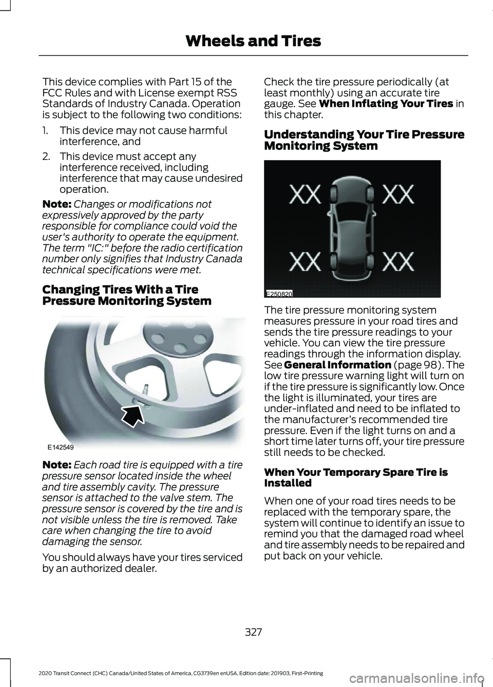
Monitoring System The tire pressure monitoring system
measures pressure in your road tires and
sends the tire pressure readings to your
vehicle. You can view the tire pressure
readings through the information display.
See General Information (page 98). The
low tire pressure warning light will turn on
if the tire pressure is significantly low. Once
the light is illuminated, your tires are
under-inflated and need to be inflated to
the manufacturer
’s recommended tire
pressure. Even if the light turns on and a
short time later turns off, your tire pressure
still needs to be checked.
When Your Temporary Spare Tire is
Installed
When one of your road tires needs to be
replaced with the temporary spare, the
system will continue to identify an issue to
remind you that the damaged road wheel
and tire assembly needs to be repaired and
put back on your vehicle.
327
2020 Transit Connect (CHC) Canada/United States of America, CG3739en enUSA, Edition date: 201903, First-Printing Wheels and TiresE142549 E250820
Page 333 of 509

When Inflating Your Tires
WARNING: Do not use the tire
pressure displayed in the information
display as a tire pressure gauge. Failure
to follow this instruction could result in
personal injury or death.
When putting air into your tires (such as at
a gas station or in your garage), the tire
pressure monitoring system may not
respond immediately to the air added to
your tires.
It may take up to two minutes of driving
over 20 mph (32 km/h) for the light to turn
off after you have filled your tires to the
recommended inflation pressure.
How Temperature Affects Your Tire
Pressure
The tire pressure monitoring system
monitors tire pressure in each pneumatic
tire. While driving in a normal manner, a
typical passenger tire inflation pressure
may increase about
2 –4 psi (14– 28 kPa)
from a cold start situation. If the vehicle is
stationary overnight with the outside
temperature significantly lower than the
daytime temperature, the tire pressure may
decrease about 3 psi (21 kPa) for a drop of
30°F (17°C) in ambient temperature. This
lower pressure value may be detected by
the tire pressure monitoring system as
being significantly lower than the
recommended inflation pressure and
activate the system warning light for low
tire pressure. If the low tire pressure
warning light is on, visually check each tire
to verify that no tire is flat. If one or more
tires are flat, repair as necessary. Check
the air pressure in the road tires. If any tire
is under-inflated, carefully drive the vehicle
to the nearest location where air can be
added to the tires. Inflate all the tires to
the recommended inflation pressure. Tire Pressure Monitoring System
Reset Procedure
Overview
You must carry out the system reset
procedure after each tire replacement or
adjustment of the tire pressures.
To maintain your vehicle load carrying
capability, your vehicle may require
different tire pressures in the front
compared to the rear. In these cases, the
system illuminates the warning lamp at
different pressures for the front and rear
tires.
If the tires are rotated, you need to reset
the system in order to relearn the positions
of the tire pressure sensors. The system
cannot tell which position a tire pressure
sensor is in, and assumes you have set the
tire pressures correctly.
Performing the Reset Procedure
1. Switch the ignition on.
2. Navigate to the tire monitor menu in
the information display. See
Information Messages (page 100).
3. Press and hold the OK button until a confirmation message appears. If your
vehicle has a tire pressure monitoring
system reset button, press and hold
the button until a confirmation
message appears.
329
2020 Transit Connect (CHC) Canada/United States of America, CG3739en enUSA, Edition date: 201903, First-Printing Wheels and Tires