steering wheel FORD WINDSTAR 2001 2.G Owners Manual
[x] Cancel search | Manufacturer: FORD, Model Year: 2001, Model line: WINDSTAR, Model: FORD WINDSTAR 2001 2.GPages: 288, PDF Size: 2.6 MB
Page 79 of 288
POSITIONS OF THE IGNITION
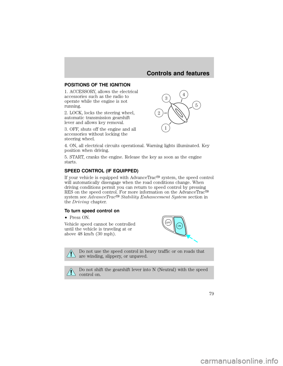
1. ACCESSORY, allows the electrical
accessories such as the radio to
operate while the engine is not
running.
2. LOCK, locks the steering wheel,
automatic transmission gearshift
lever and allows key removal.
3. OFF, shuts off the engine and all
accessories without locking the
steering wheel.
4. ON, all electrical circuits operational. Warning lights illuminated. Key
position when driving.
5. START, cranks the engine. Release the key as soon as the engine
starts.
SPEED CONTROL (IF EQUIPPED)
If your vehicle is equipped with AdvanceTracysystem, the speed control
will automatically disengage when the road conditions change. When
driving conditions permit you can return to speed control by pressing
RES on the speed control. For more information on the AdvanceTracy
system seeAdvanceTracyStability Enhancement Systemsection in
theDrivingchapter.
To turn speed control on
²Press ON.
Vehicle speed cannot be controlled
until the vehicle is traveling at or
above 48 km/h (30 mph).
Do not use the speed control in heavy traffic or on roads that
are winding, slippery, or unpaved.
Do not shift the gearshift lever into N (Neutral) with the speed
control on.
3
1
2
5
4
OFF
ON
Controls and features
79
Page 84 of 288
TILT STEERING WHEEL (IF EQUIPPED)
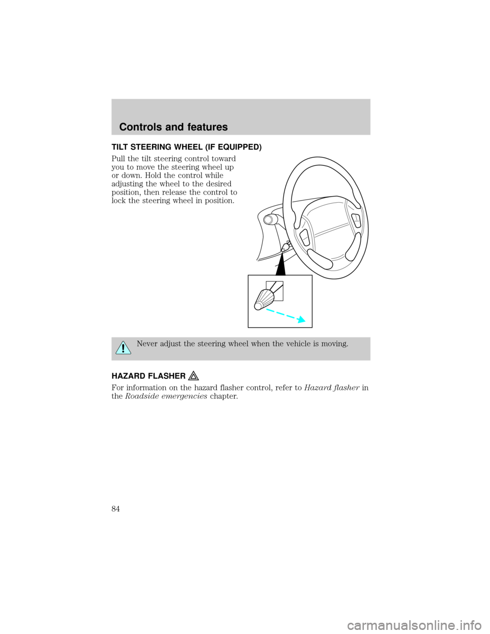
Pull the tilt steering control toward
you to move the steering wheel up
or down. Hold the control while
adjusting the wheel to the desired
position, then release the control to
lock the steering wheel in position.
Never adjust the steering wheel when the vehicle is moving.
HAZARD FLASHER
For information on the hazard flasher control, refer toHazard flasherin
theRoadside emergencieschapter.
Controls and features
84
Page 164 of 288
2. Make sure the headlamps and vehicle accessories are off.
3. Make sure the gearshift is in P
(Park).
4. Make sure the parking brake is
set.
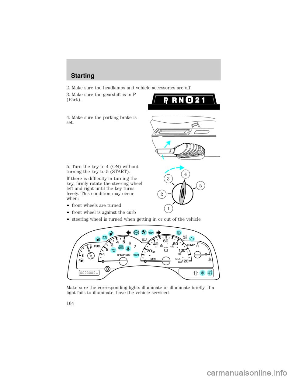
5. Turn the key to 4 (ON) without
turning the key to 5 (START).
If there is difficulty in turning the
key, firmly rotate the steering wheel
left and right until the key turns
freely. This condition may occur
when:
²front wheels are turned
²front wheel is against the curb
²steering wheel is turned when getting in or out of the vehicle
Make sure the corresponding lights illuminate or illuminate briefly. If a
light fails to illuminate, have the vehicle serviced.
1
2
34
5
40
4080
120
160
20020
12345
6
760
80100
120MPH RPMX1000 THEFT
TRAC
ACTIVE TRAC
OFFTEMP
H
FFUEL
E
km/h
BRAKE
mi
O/D
OFF
Starting
164
Page 167 of 288
BRAKES
Your service brakes are self-adjusting. Refer to the scheduled
maintenance guide for scheduled maintenance.
Occasional brake noise is normal and often does not indicate a
performance concern with the vehicle's brake system. In normal
operation, automotive brake systems may emit occasional or intermittent
squeal or groan noises when the brakes are applied. Such noises are
usually heard during the first few brake applications in the morning;
however, they may be heard at any time while braking and can be
aggravated by environmental conditions such as cold, heat, moisture,
road dust, salt or mud. If a ªmetal-to-metal,º ªcontinuous grindingº or
ªcontinuous squealº sound is present while braking, the brake linings
may be worn-out and should be inspected by a qualified service
technician.
Anti-lock brake system (ABS)
On vehicles equipped with an anti-lock braking system (ABS), a noise
from the hydraulic pump motor and pulsation in the pedal may be
observed during ABS braking events. Pedal pulsation coupled with noise
while braking under panic conditions or on loose gravel, bumps, wet or
snowy roads is normal and indicates proper functioning of the vehicle's
anti-lock brake system. The ABS performs a self-check after you start
the engine and begin to drive away. A brief mechanical noise may be
heard during this test. This is normal. If a malfunction is found, the ABS
warning light will come on. If the vehicle has continuous vibration or
shudder in the steering wheel while braking, the vehicle should be
inspected by a qualified service technician.
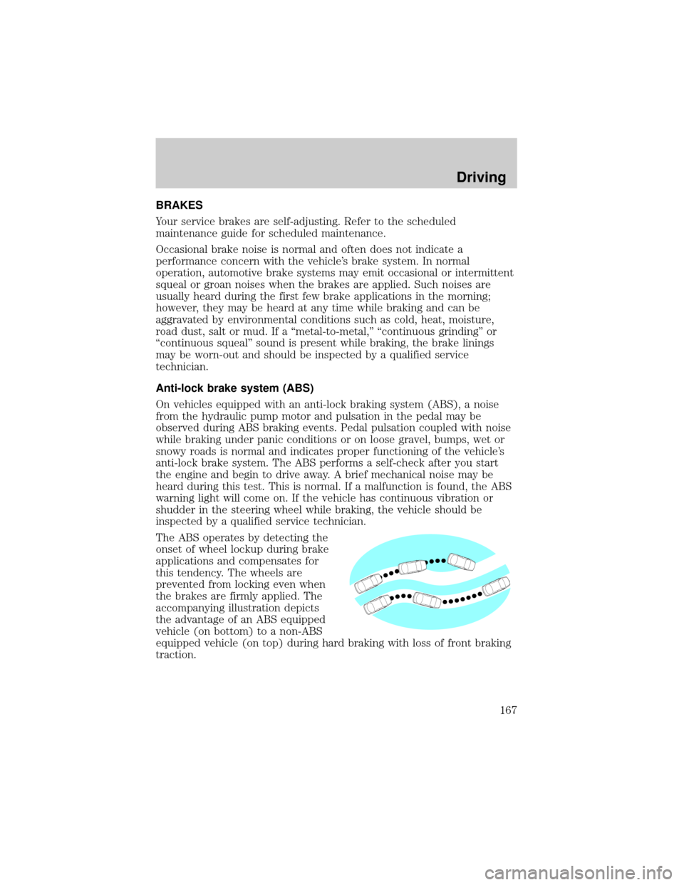
The ABS operates by detecting the
onset of wheel lockup during brake
applications and compensates for
this tendency. The wheels are
prevented from locking even when
the brakes are firmly applied. The
accompanying illustration depicts
the advantage of an ABS equipped
vehicle (on bottom) to a non-ABS
equipped vehicle (on top) during hard braking with loss of front braking
traction.
Driving
167
Page 168 of 288
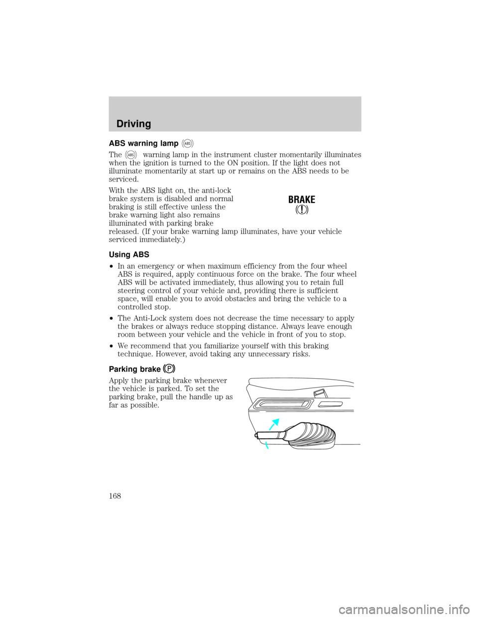
ABS warning lampABS
TheABSwarning lamp in the instrument cluster momentarily illuminates
when the ignition is turned to the ON position. If the light does not
illuminate momentarily at start up or remains on the ABS needs to be
serviced.
With the ABS light on, the anti-lock
brake system is disabled and normal
braking is still effective unless the
brake warning light also remains
illuminated with parking brake
released. (If your brake warning lamp illuminates, have your vehicle
serviced immediately.)
Using ABS
²In an emergency or when maximum efficiency from the four wheel
ABS is required, apply continuous force on the brake. The four wheel
ABS will be activated immediately, thus allowing you to retain full
steering control of your vehicle and, providing there is sufficient
space, will enable you to avoid obstacles and bring the vehicle to a
controlled stop.
²The Anti-Lock system does not decrease the time necessary to apply
the brakes or always reduce stopping distance. Always leave enough
room between your vehicle and the vehicle in front of you to stop.
²We recommend that you familiarize yourself with this braking
technique. However, avoid taking any unnecessary risks.
Parking brake
Apply the parking brake whenever
the vehicle is parked. To set the
parking brake, pull the handle up as
far as possible.
!
BRAKE
Driving
168
Page 170 of 288
The Traction Controlysystem will assist you in making better use of
available traction on slippery surfaces. The system is a driver aid which
makes your vehicle easier to handle primarily on snow and ice covered
roads.
During Traction Controlyoperation, TRACTION CONTROL OK is
displayed on the message center (if equipped). You may hear an electric
motor type of sound coming from the engine compartment and the
engine will not ªrev-upº when you push further on the accelerator. This
is normal system behavior.
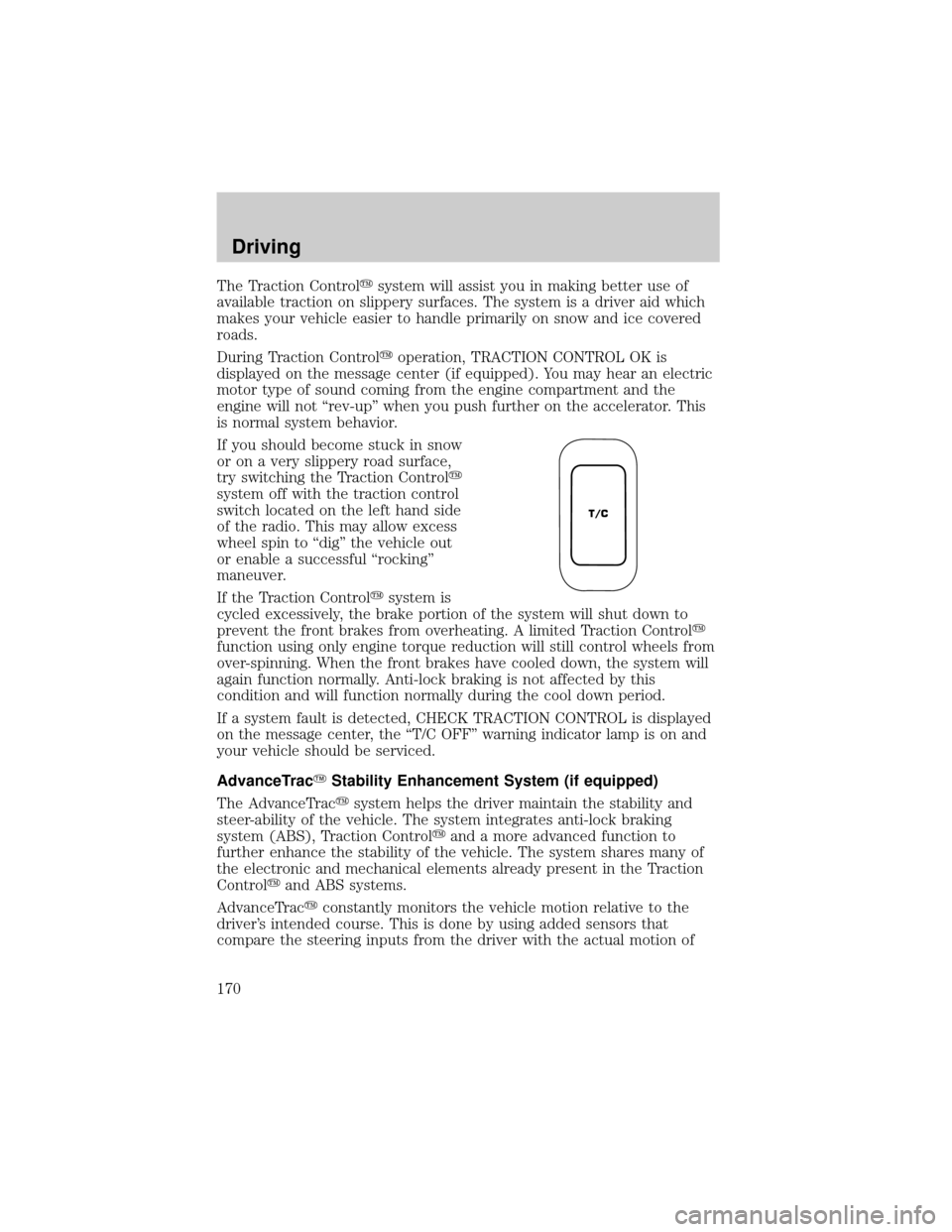
If you should become stuck in snow
or on a very slippery road surface,
try switching the Traction Controly
system off with the traction control
switch located on the left hand side
of the radio. This may allow excess
wheel spin to ªdigº the vehicle out
or enable a successful ªrockingº
maneuver.
If the Traction Controlysystem is
cycled excessively, the brake portion of the system will shut down to
prevent the front brakes from overheating. A limited Traction Controly
function using only engine torque reduction will still control wheels from
over-spinning. When the front brakes have cooled down, the system will
again function normally. Anti-lock braking is not affected by this
condition and will function normally during the cool down period.
If a system fault is detected, CHECK TRACTION CONTROL is displayed
on the message center, the ªT/C OFFº warning indicator lamp is on and
your vehicle should be serviced.
AdvanceTracYStability Enhancement System (if equipped)
The AdvanceTracysystem helps the driver maintain the stability and
steer-ability of the vehicle. The system integrates anti-lock braking
system (ABS), Traction Controlyand a more advanced function to
further enhance the stability of the vehicle. The system shares many of
the electronic and mechanical elements already present in the Traction
Controlyand ABS systems.
AdvanceTracyconstantly monitors the vehicle motion relative to the
driver's intended course. This is done by using added sensors that
compare the steering inputs from the driver with the actual motion of
T/C
Driving
170
Page 173 of 288
If you find yourself regularly experiencing AdvanceTracyevents,
you are driving too fast for conditions, you should reduce your
speed, and drive less aggressively. Speed Control should NOT be used
under these conditions. AdvanceTrac is limited by the laws of physics.
It is always possible to lose control of a vehicle due to inappropriate
driver inputs for the conditions. The occurrence of an AdvanceTracy
event is an indication that at least some of the tires have exceeded
their ability to grip the road; this may cause you to lose control of the
vehicle increasing the risk of severe personal injury or property
damage.
STEERING
Your vehicle is equipped with power steering. Power steering uses energy
from the engine to help steer the vehicle.
To prevent damage to the power steering pump:
²Never hold the steering wheel to the extreme right or the extreme left
for more than a few seconds when the engine is running.
²Do not operate the vehicle with a low power steering pump fluid level
(below the MIN mark on the reservoir).
If the power steering system breaks down (or if the engine is turned
off), you can steer the vehicle manually, but it takes more effort.
If the steering wanders or pulls, the condition could be caused by any of
the following:
²underinflated tire(s) on any wheel(s)
²uneven vehicle loading
²high crown in center of road
²high crosswinds
²wheels out of alignment
²loose or worn suspension components
AUTOMATIC TRANSAXLE OPERATION
Brake-shift interlock
This vehicle is equipped with a brake-shift interlock feature that prevents
the gearshift lever from being moved from P (Park) unless the brake
pedal is depressed.
Driving
173
Page 188 of 288
NOTE:Always replace a fuse with one that has the specified amperage
rating. Using a fuse with a higher amperage rating can cause severe wire
damage and could start a fire.
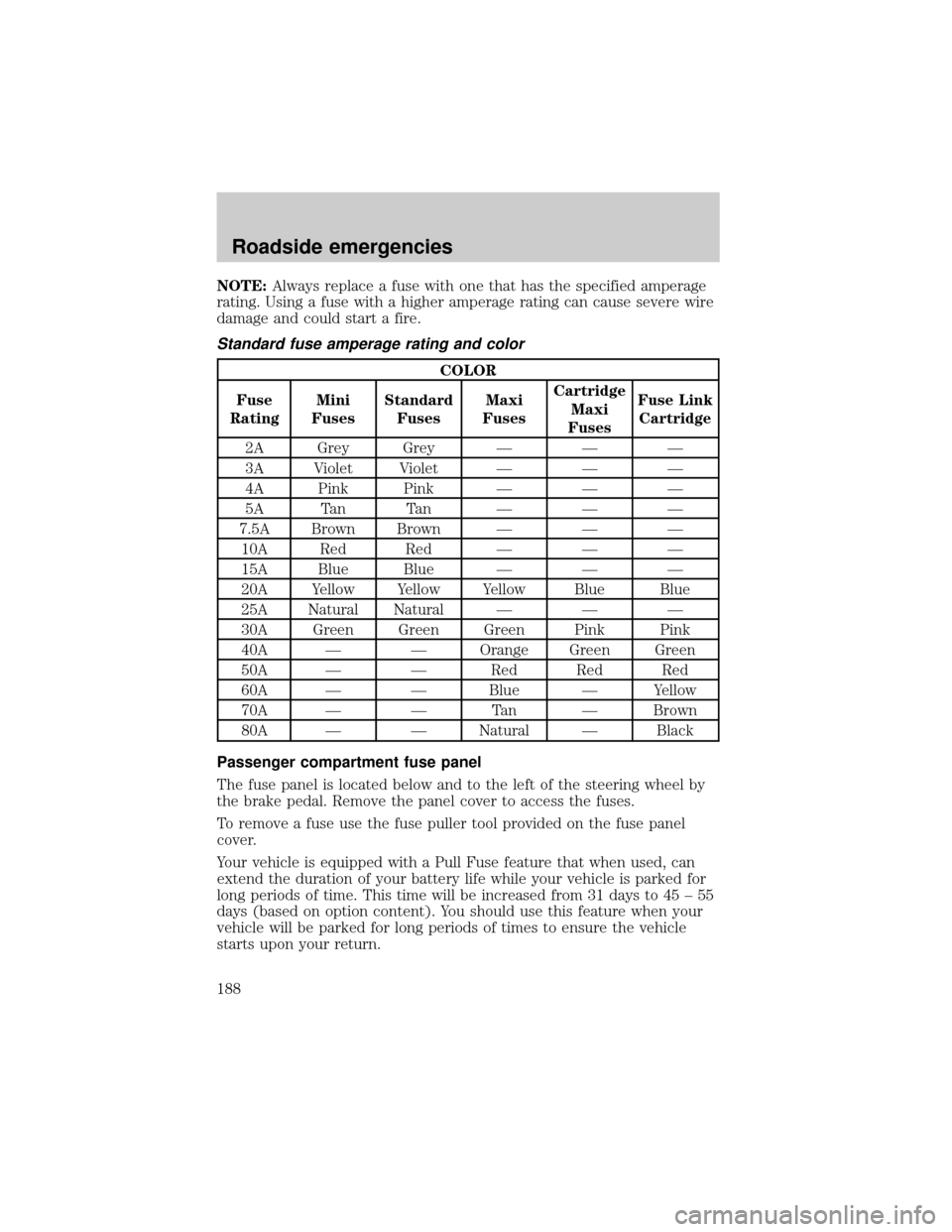
Standard fuse amperage rating and color
COLOR
Fuse
RatingMini
FusesStandard
FusesMaxi
FusesCartridge
Maxi
FusesFuse Link
Cartridge
2A Grey Grey Ð Ð Ð
3A Violet Violet Ð Ð Ð
4A Pink Pink Ð Ð Ð
5A Tan Tan Ð Ð Ð
7.5A Brown Brown Ð Ð Ð
10A Red Red Ð Ð Ð
15A Blue Blue Ð Ð Ð
20A Yellow Yellow Yellow Blue Blue
25A Natural Natural Ð Ð Ð
30A Green Green Green Pink Pink
40A Ð Ð Orange Green Green
50A Ð Ð Red Red Red
60A Ð Ð Blue Ð Yellow
70A Ð Ð Tan Ð Brown
80A Ð Ð Natural Ð Black
Passenger compartment fuse panel
The fuse panel is located below and to the left of the steering wheel by
the brake pedal. Remove the panel cover to access the fuses.
To remove a fuse use the fuse puller tool provided on the fuse panel
cover.
Your vehicle is equipped with a Pull Fuse feature that when used, can
extend the duration of your battery life while your vehicle is parked for
long periods of time. This time will be increased from 31 days to 45 ± 55
days (based on option content). You should use this feature when your
vehicle will be parked for long periods of times to ensure the vehicle
starts upon your return.
Roadside emergencies
188
Page 191 of 288
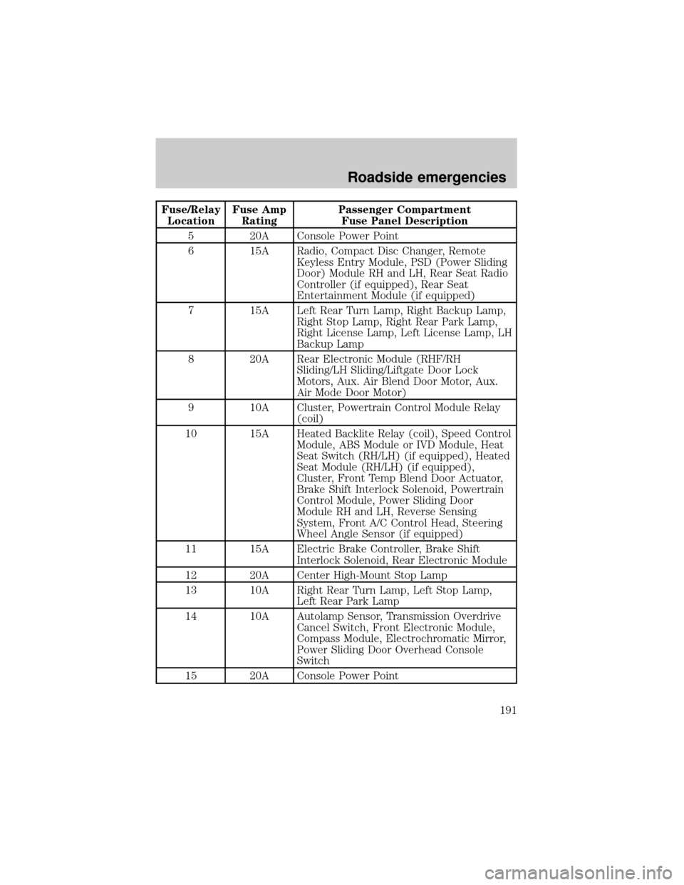
Fuse/Relay
LocationFuse Amp
RatingPassenger Compartment
Fuse Panel Description
5 20A Console Power Point
6 15A Radio, Compact Disc Changer, Remote
Keyless Entry Module, PSD (Power Sliding
Door) Module RH and LH, Rear Seat Radio
Controller (if equipped), Rear Seat
Entertainment Module (if equipped)
7 15A Left Rear Turn Lamp, Right Backup Lamp,
Right Stop Lamp, Right Rear Park Lamp,
Right License Lamp, Left License Lamp, LH
Backup Lamp
8 20A Rear Electronic Module (RHF/RH
Sliding/LH Sliding/Liftgate Door Lock
Motors, Aux. Air Blend Door Motor, Aux.
Air Mode Door Motor)
9 10A Cluster, Powertrain Control Module Relay
(coil)
10 15A Heated Backlite Relay (coil), Speed Control
Module, ABS Module or IVD Module, Heat
Seat Switch (RH/LH) (if equipped), Heated
Seat Module (RH/LH) (if equipped),
Cluster, Front Temp Blend Door Actuator,
Brake Shift Interlock Solenoid, Powertrain
Control Module, Power Sliding Door
Module RH and LH, Reverse Sensing
System, Front A/C Control Head, Steering
Wheel Angle Sensor (if equipped)
11 15A Electric Brake Controller, Brake Shift
Interlock Solenoid, Rear Electronic Module
12 20A Center High-Mount Stop Lamp
13 10A Right Rear Turn Lamp, Left Stop Lamp,
Left Rear Park Lamp
14 10A Autolamp Sensor, Transmission Overdrive
Cancel Switch, Front Electronic Module,
Compass Module, Electrochromatic Mirror,
Power Sliding Door Overhead Console
Switch
15 20A Console Power Point
Roadside emergencies
191
Page 196 of 288
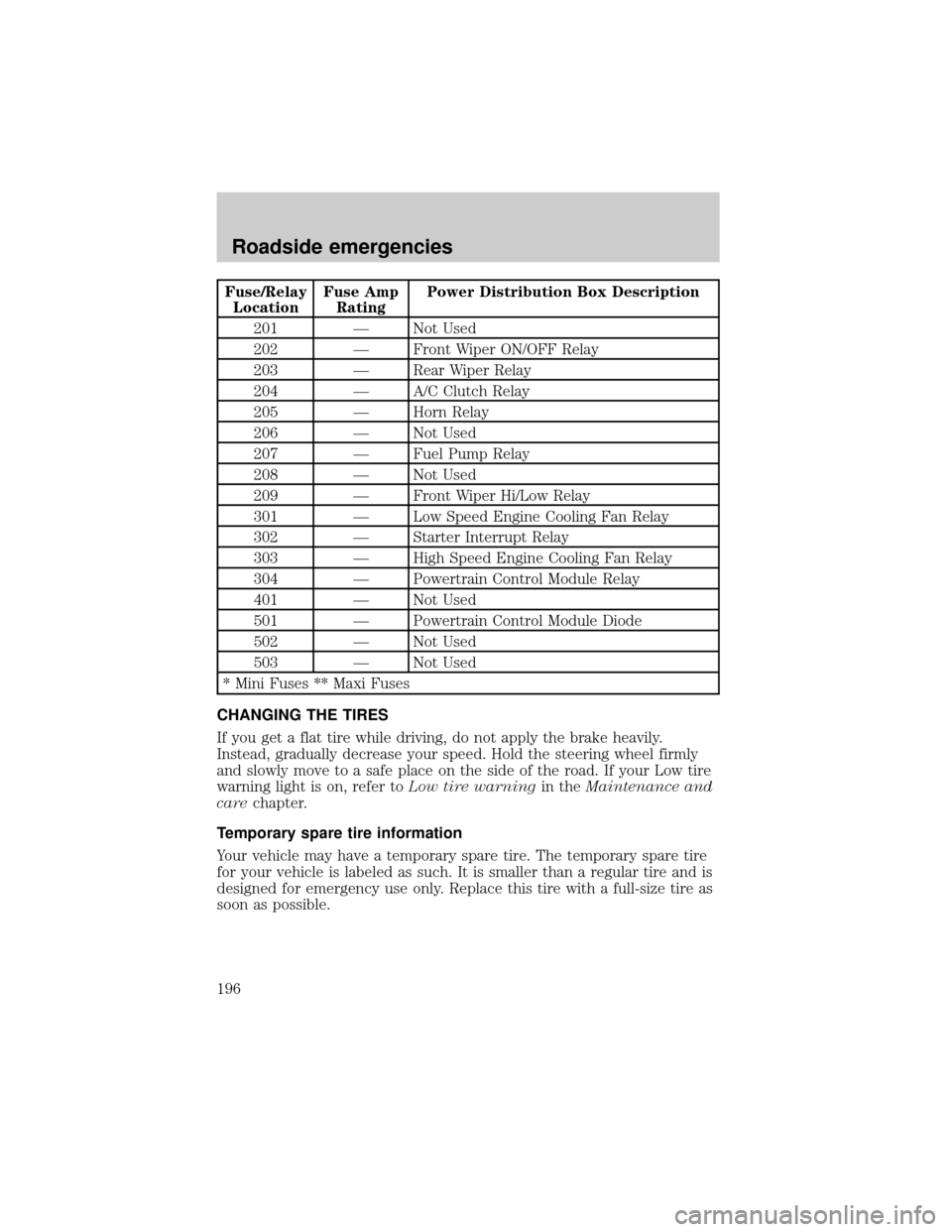
Fuse/Relay
LocationFuse Amp
RatingPower Distribution Box Description
201 Ð Not Used
202 Ð Front Wiper ON/OFF Relay
203 Ð Rear Wiper Relay
204 Ð A/C Clutch Relay
205 Ð Horn Relay
206 Ð Not Used
207 Ð Fuel Pump Relay
208 Ð Not Used
209 Ð Front Wiper Hi/Low Relay
301 Ð Low Speed Engine Cooling Fan Relay
302 Ð Starter Interrupt Relay
303 Ð High Speed Engine Cooling Fan Relay
304 Ð Powertrain Control Module Relay
401 Ð Not Used
501 Ð Powertrain Control Module Diode
502 Ð Not Used
503 Ð Not Used
* Mini Fuses ** Maxi Fuses
CHANGING THE TIRES
If you get a flat tire while driving, do not apply the brake heavily.
Instead, gradually decrease your speed. Hold the steering wheel firmly
and slowly move to a safe place on the side of the road. If your Low tire
warning light is on, refer toLow tire warningin theMaintenance and
carechapter.
Temporary spare tire information
Your vehicle may have a temporary spare tire. The temporary spare tire
for your vehicle is labeled as such. It is smaller than a regular tire and is
designed for emergency use only. Replace this tire with a full-size tire as
soon as possible.
Roadside emergencies
196