air condition GEELY CK 2008 User Guide
[x] Cancel search | Manufacturer: GEELY, Model Year: 2008, Model line: CK, Model: GEELY CK 2008Pages: 392, PDF Size: 38.86 MB
Page 166 of 392

1594Make a simulation test in a way of symptom simulation
5Inspect DTC
6Confirm symptomV. SYMPTOM SIMULATIONNOTES:
The most difficult conditions to handle in the fault troubleshooting are that the fault symptom dose not appear.
Under the circumstances, make sure first to make a comprehensive analysis to the fault described by the
customer, then to simulate an environment that is similar or the same with the conditions when the fault of the
customer's vehicle occurred. No matter how rich the experience of the technician is and how skillful he is, if
he make a fault troubleshooting analysis without confirm the fault symptom, it is inevitable for him to neglect
some important factors and incorrectly guess, which may cause barriers to repair. For example, if a fault
occurs only when the engine is cool or if a fault occurs only caused by a vibration from pavement and so on,
when the engine is checked in the hot or static state, it is no way to confirm. Because of vibration, high-
temperature or seeping water (Vapor) often causes some faults that are difficult to reappear. So, here are
some effective symptom simulation tests.
KEY POINTS OF SYMPTOM SIMULATION TEST:
In the symptom simulation test, no doubt it is important to confirm the fault symptom, but the fault position or
fault components must be also found out. So, before the test and the pre-inspection of connection, narrow the
range of the circuit where faults may occur according to the fault symptom. Then make a symptom simula-
tion test to see if the circuit measured is normal; the fault symptom is also verified at the same time.
1. Way of Vibration: When vibration may be the major cause of the fault.
For example:
(a) Use your hand to gently vibrate the sensor that is considered the cause of the fault, in order to check if it
is ineffective.
(b) Softly rock the connector and harness in horizontal and vertical direction.
Notes: Hard rock may cause the relay circuit open.
2. Way of Spraying Water: When rainy weather or wet environment may be the major cause of the fault.
(a) Spray water on the vehicle to check if the fault occurs.
NOTES:
�yBe sure not to directly spray water into the engine compartment. Spray the water on the face of the
radiator to change the temperature and humidity indirectly.
�yBe sure not to spray water onto electronic devices and controllers.
Page 183 of 392

176(b) Inspect the combination meter connectors.
1 Inspect continuity
�yDisconnect the connector from the combination meter assembly
�y Inspect continuity between terminals
Standard:
2Inspect voltage
�yDisconnect the connector from the combination meter assembly
�yTurn the ignition switch ON
�yInspect voltage between terminals
Standard:
Result and solution:
NormalReplace the combination meter assembly
AbnormalRepair or replace the harness or connectorTe ste r c onne c tion Condition Sta ndard c ondition
B4 - ground Turn the ignition switc h ON 10 – 14VTe ste r c onne c tion Condition Sta nda rd c ondition
B7 - ground Norma l condition Continuity
B8 - ground Norma l condition Continuity
Page 186 of 392

179�yInspect voltage between terminals
Standard:
Result and solution:
AbnormalRepair or replace the harness or connector
NormalInspect the speed sensor output signal
3Inspect the speed sensor output signal
Inspect voltage
�yHold the front wheels up
�yPush the shift lever to NEUTRAL
�yTurn the ignition switch to ON
�ySlowly turn the front wheel, measure the voltage between terminal 1 and 2
Standard voltage is as follows:
Voltage changes alternately
Result and solution:
NormalRepair or replace the harness or connector
Abnormalreplace the speed sensorTurning WheelsBelow 0.5VTe ste r c onne c tion Condition Sta nda rd c ondition
3 - ground Turn the ignition switch to ON 7.5 – 9V
Page 187 of 392

180(c) Inspect the combination meter assembly
1Remove the combination meter assembly and disconnect connectors.
2 Inspect continuity
�yInspect continuity between terminals
Standard:
3Inspect voltage between terminals
Result and solution:
AbnormalRepair or replace the harness or connector
NormalReplace the combination meter assemblyTeste r c onne ction Condition Sta ndard c ondition
B7 - ground Normal c ondition Continuity
B8 - ground Normal c ondition ContinuityTe ste r c onne c tion Condition Sta nda rd c ondition
B4 - ground Turn the ignition switch to ON 10 – 14V
Page 191 of 392

184Standard:
Result and solution:
NormalReplace the combination meter assembly
If abnormalinspect the water temperature sensor
2Inspect the water temperature sensor
�yRemove the water temperature sensor and put it into the constant temperature cabinet.
�yAdjust the temperature in the constant temperature cabinet and measure the resistance of the
water temperature sensor.
Standard:
Result and solution:
NormalRepair or replace the harness and connector
If abnormalreplace the water temperature sensorTe ste r c onne c tion Condition Standa rd condition
C(60℃
)164.5±5Ω
1/2C(90℃
) 56±3Ω
H(115℃
)28.7±2Ω B5 - groundC ondit ion S t a nda r d c ondit ion
C(60℃
) 164.5±5Ω
1/2C(90℃
)56±3Ω
H(115℃
) 28.7±2Ω
Page 193 of 392

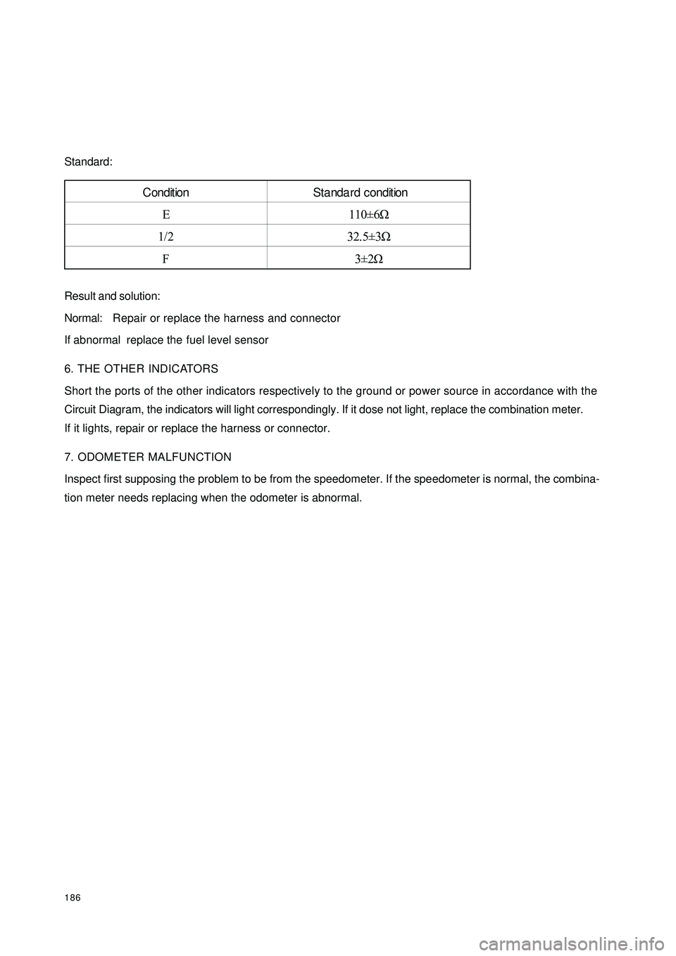
186Standard:
Result and solution:
Normal:Repair or replace the harness and connector
If abnormal replace the fuel level sensor
6. THE OTHER INDICATORS
Short the ports of the other indicators respectively to the ground or power source in accordance with the
Circuit Diagram, the indicators will light correspondingly. If it dose not light, replace the combination meter.
If it lights, repair or replace the harness or connector.
7. ODOMETER MALFUNCTION
Inspect first supposing the problem to be from the speedometer. If the speedometer is normal, the combina-
tion meter needs replacing when the odometer is abnormal.Condition Standa rd condition
E 110±6Ω
1/2 32.5±3Ω
F3±2Ω
Page 229 of 392

222(2) Multipath transfer
Noise caused by bouncing of radio waves off
obstructions is called "multipath transfer".
Multipath transfer occurs when a signal from
the broadcast transmitter antenna reflects off
buildings and mountains and interferes with
the signal that is received directly.
(3) Fade out
Because FM radio waves are of higher frequen-
cies than AM radio waves, they are reflected
off buildings, mountains, and other obstructions.
For this reason, FM signals often seem to gradu-
ally disappear or fade away as the vehicle goes
behind a building or other obstructions. This is
called "fade out".
4. Noise faults
For noise troubleshooting it is very important to understand the feedback information from the customers
well, so make the best use of the following questionnaire and diagnose the fault accurately.
HINT:
In the case that the noise occurrence condition does not meet any of the above, check based on the "Recep-Multipath
TransferFade outR a dio W a veO pe ra ting c ondition w he n
noise oc c ursCause
Noise occurs at a specific
place.Strong possibility of fore ign noise .
Noise occurs when listening
to fa int broa dc asting.There is a case that the same program is broadcasted from
each local station and that may be the case you are liste ning
to different station if the program is the same.
N oise occ urs only at night.Strong possibility of the inte rfe re nce from fa r dista nt
broa dca sting.
N o is e o c c u r s w h ile d r iv in g
and at a specific place.Strong possibility of multipath tra nsfer inte rfe re nc e a nd
caused by the changes of FM waves. AM
FM
Page 233 of 392

226II. Inspection1. Power switch system doesn't work
Wiring Diagram
(1) Check radio assembly (+B, ¬ACC, ¬GND)
1Check the continuity between terminals under each operating condition as shown in the table below
Standard:
2Check the voltage between terminals under each operating condition as shown in the table
Standard:
Normal:Repair or replace wire harness, connector
Abnormal:Check or replace radio assemblyMain Fuse BoxRadio and CD
BatteryFusible Link BoxIgnition SwitchTester connection Condition Standard Status
GND Consta nt Status ContinuityTeste r Connec tion Condition Sta nda rd Sta tus
+B - GND Consta nt Status 10~
14V
ACC - GND Ignition switch ACC or ON 10~
14V
Page 234 of 392

2272. The radio backlight does not light up with the illumination switch ON
Wiring Diagram
(1) Check radio assembly (TAIL)
Check the voltage between terminals under each operating condition as shown in the table below.
Standard:
Abnormal:Repair or replace wire harness and connector
Normal:Check and replace radio assemblyMain Fuse BoxRadio and CDFusible Link Box
BatteryLight
Control
Switch
BatteryTeste r Connec tion Condition Sta nda rd Sta tus
TAIL - GND Combined Switch (Light switc h) 10~
14V
Page 236 of 392

229(3) Tweeter speaker assembly inspection
1Disconnect speaker connector
2Check resistance
Notice:
Do not remove the speaker during inspection.
Standard Value: 4Ω¸
AbnormalReplace tweeter speaker assembly
NORMALCheck wire harness and connector
(4) Check front speaker assembly
1Disconnect speaker connector
2Check resistance
Standard Value: 4Ω¸
Abnormal:Replace front speaker assembly
Normal:Check wire harness and connector
(5) Check rear speaker assembly
1Disconnect speaker connector
2Check resistance
Standard Value: 4¸
Abnormal:Replace rear speaker assembly
Normal:Check wire harness and connector
(6) Check wire harness and connector
Abnormal:Repair or replace wire harness and connector
Normal:Check and replace radio assembly
(7) Check and replace radio assembly (+B, ACC, GND)
(a) Check the continuity between terminals under each operating condition as shown in the table below.
Standard:
(b) Check the voltage between terminals under each operating condition as shown in the table below.
Standard:
Normal:Repair or replace wire harness and connector
Abnormal:Check and replace radio assemblyTester connection Condition Standard Status
GND Consta nt Status ContinuityTeste r Connec tion Condition Sta nda rd Sta tus
+B - GND Consta nt Status 10~
14V
ACC - GND Ignition switch ACC or ON 10~
14VΩ