bulb GEELY CK 2008 User Guide
[x] Cancel search | Manufacturer: GEELY, Model Year: 2008, Model line: CK, Model: GEELY CK 2008Pages: 392, PDF Size: 38.86 MB
Page 226 of 392

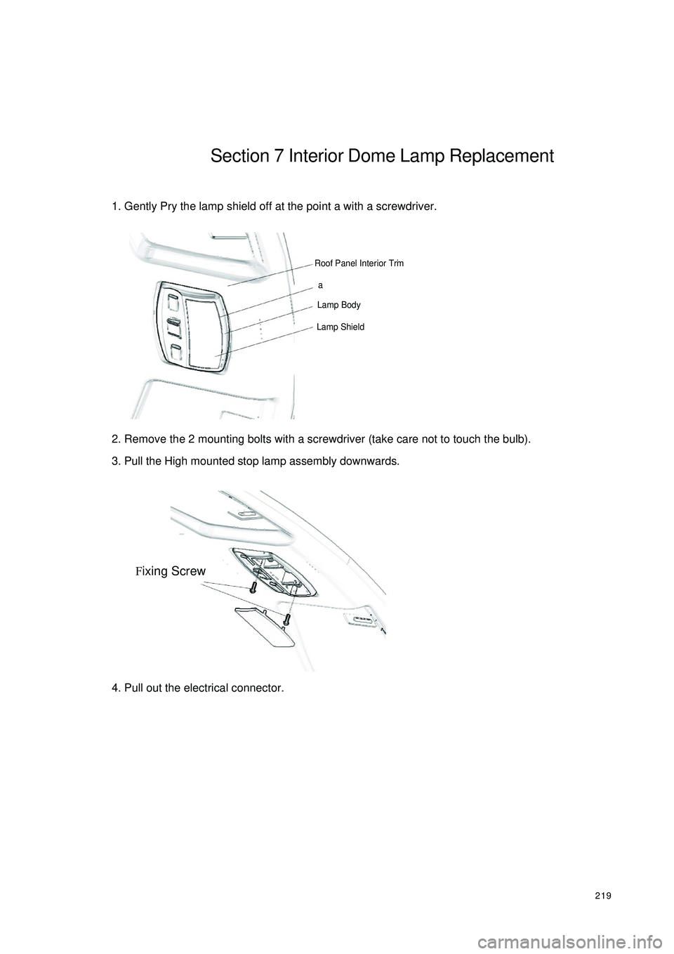
219Section 7 Interior Dome Lamp Replacement1. Gently Pry the lamp shield off at the point a with a screwdriver.
2. Remove the 2 mounting bolts with a screwdriver (take care not to touch the bulb).
3. Pull the High mounted stop lamp assembly downwards.
4. Pull out the electrical connector.Roof Panel Interior Trim
Lamp Body
Lamp ShieldaFixing Screw
Page 252 of 392

2454. Trouble Identification
(1) Trouble Record (DTC storage)
When the circular diagnostic tests are involved in identification of a trouble, the SRS ECU (HAE2.5) will
store relevant codes, first/last diagnosis time and frequency of the trouble in EEPROM.
�ySRS ECU (HAE2.5) can store up to 6 troubles, low voltage trouble as well as two crash records (front
and side).
�yThe transmit of the DTCs are carried out in the way that the SRS ECU£¨HAE2.5£©via serial data
interface of the maintenance procedures assign the codes to the diagnostic detector.No. Trouble De scription Trouble shooting
1Ignition c irc uit 1 (drive r a irba g), high re sista nc e or ope n
circui
tYes
2Ignition circuit 1 (driver airbag), low resistance or short
circuitYes
3 Ignition circuit 1 (driver airbag), groundYes
4Ignition c irc uit 1 (drive r a irba g), connec te d to power
sourc eYes
5Ignition circuit 2 (passenger airbag), high resistance or
ope n c irc ui
tYes
6Ignition circuit 2 (passenger airbag), low resistance or
short c ircuitYes
7 Ignition circuit 2 (passenger airbag), groundYes
8Ignition circuit 2 (passenger airbag), connected to power
sourc eYes
9Ignition c irc uit 3 (drive r se a t belt pre tensione r), high
re sista nc e or ope n c irc uitYes
10Ignition c irc uit 3 (drive r se a t belt pre tensione r), low
resistance or short circui
tYes
11 Ignition c irc uit 3 (drive r se a t belt pre tensione r), groundYes
12Ignition c irc uit 3 (drive r se a t belt pre tensione r),
connec te d to power sourc eYes
13Ignition circuit 4 (passenger seat belt pretensioner), high
re sista nc e or ope n c irc uitYes
14Ignition circuit 4 (passenger seat belt pretensioner), low
resistance or short circui
tYes
15Ignition circuit 4 (passenger seat belt pretensioner),
groun
dYes
16Ignition circuit 4 (passenger seat belt pretensioner),
connec te d to power sourc eYes
17 High volta ge of powe r source Ye s
18 Low voltage of powe r sourc e Ye s
19Wa rning light trouble -c onne c te d to powe r sourc e or
short c ircuit of the light bulbYes
20 Wa rning light trouble -ground or fila me nt ope n c ircuit Ye s
21 Missing/mista ke of the algorithm parame te rs
No (replace SRS ECU (HAE2.5))
22 Previous crash recorde
dNo (replace SRS ECU (HAE2.5)) DTCs as re c ognize d by SRS ECU (HAE2.5)
Page 253 of 392

246 The transmit of the DTCs are carried out in the way that the SRS ECU (HAE2.5) via serial data interface
of the maintenance procedures assign the codes to the diagnostic detector.23 C ommunication trouble Y e s
24 Inte rna l trouble (se e the follow ing ta ble )No (replace SRS ECU (HAE2.5))
25PADS (
passenger airbag deactivation
sw itch)
, connected to power source or open
circuitYes
26PADS (
passenger airbag deactivation
sw itch)
, ground or short c irc uitYes
27 PADS (passenger airbag switch), trouble Yes
28 C ra sh output pin, ground Y e s
29C ra sh output pin, short c irc uite d to pow e r
sourceYes
30PADI (passenger airbag deactivation switch
indic ator light) error, c onnected to pow er source
or light bulb short c irc uitYes
31PADI (passenger airbag deactivation switch
indic a tor light) e rror, ground or ope n c irc uitYes
32 Se a t be lt pre te nsione r se pa ra te ignition Y e s, up to 5 time s
33Se a t be lt pre te nsione r se pa ra te ignition for 6
time sNo (replace SRS ECU (HAE2.5))No. Trouble De sc ription DTC
1 Ignition c irc uit 1 (drive r a irba g), high re sistanc e or ope n circ uit B1 346
2 Ignition c irc uit 1 (drive r a irba g), low re sista nc e or short c irc uit B1 347
3 Ignition c irc uit 1 (drive r a irba g), groundB1 348
4 Ignition c irc uit 1 (drive r a irba g), c onne cte d to powe r sourc e B1 349
5 Ignition c irc uit 2 (pa sse nge r a irbag), high re sista nc e or ope n c ircuit B1 352
6 Ignition c irc uit 2 (pa sse nge r a irbag), low resista nce or short c irc uit B1 353
7 Ignition c irc uit 2 (pa sse nge r a irbag), groundB1 354
8 Ignition circuit 2 (passenger airbag), connected to power source B1 355
9 Ignition c irc uit 3 (drive r se a t belt pre te nsione r), high re sista nc e or ope n c ircuit B1 361
10 Ignition c irc uit 3 (drive r se a t belt pre te nsione r), low resista nce or short c irc uit B1 362
11 Ignition c irc uit 3 (drive r se a t belt pre te nsione r), ground B1 363
12 Ignition c irc uit 3 (drive r se a t belt pre te nsione r), c onne c t to power sourc e B1 364
13Ignition c ircuit 4 (passe nger se a t be lt pre tensione r), high re sista nc e or open
circuitB1 367 Diagnostic DTCs
Page 254 of 392

247(2) Internal troubles
The micro controller can check the following items not
only in the initiation check but also in the circular diagnos-
tic check.
1Trigger transistor of ignition circuit: high-end transistor
can be checked not only in the initiation check but
also in the circular diagnostic check. However, since
the low-end transistor is open when connected in short
circuit to power source, it can only be checked in the
initiation check to avoid explosion.
2The ignition voltage is provided by supercharge
converter.
3The acceleration sensor performs selfcheck in the
initiation check.
4Range of allowed deviation of acceleration sensor in the circular diagnostic check.
5Microcontroller includes AD converter, ROM, RAM, etc.
6Status of safety sensor.NOTICE
The connectors of the squib circuit contain a
shorting bar. When the connector is not
connected, the unexpected deployment is
caused by the short in the circuit arising from
the contact of the positive (+) and negative (-)
terminals or the static electricity. If there is
poor connection for connectors, the symptom
may not be removed even when the shorting
bar is connected.14Ignition c irc uit 4 (passe nger se a t be lt pre tensione r), low re sistanc e
or short c irc uitB1 368
15 Ignition c ircuit 4 (passe nger se a t be lt pre tensione r), groundB1 369
16Ignition c ircuit 4 (passe nger se a t belt pre te nsione r), c onne c t topowe r sourceB1 370
17 High volta ge of powe r sourc e B1 111
18 Low volta ge of power sourc e B1 112
19Warning light trouble -c onne c te d to powe r sourc e or light bulb short
circuitB2 500
20 Warning light trouble -ground or filame nt ope n circ uitB2 500
21 Missing/mistake of the algorithm parameters B1 661
22 Previous crash recordedB1 650
23 Communic a tion trouble B1 407
23 Inte rna l trouble (se e the following ta ble) B1 620
24PADS(
pa ssenge r airba g de a ctiva tion switch)
, c onne c ted topowe r source or open c irc uitB1 527
25PADS(
passenger airbag deactivation switch)
, ground or short
circuitB1 528
26 PADS (passenger airbag deactivation switch), trouble B1 529
27 Cra sh output pin, groundB1 676
28 Cra sh output pin, short c irc uite d to power sourc e B1 677
29PADI (passenger airbag deactivation switch indicator light) error,
c onne c ted to powe r sourc e or light bulb short c irc uitB2 505
30PADI (passenger airbag deactivation switch indicator light) error,
ground or open c irc uitB2 505
31 Se a t be lt pre tensione r se pa ra te ignitionB1 657
32 Se a t be lt pre tensione r se pa ra te ignition for 6 time s B1 658
Page 256 of 392

249(3) Clear DTCs
When ECU diagnostic tester (Hi-DSTM) receives the "Clear DTCs" command from the serial interface,
the DTCs stored in ECU will be cleared off. But if an internal DTC is recorded or there is one crash
record, the command will not be executed.
5. Trouble display (Warning light ON)
(1) Light bulb check
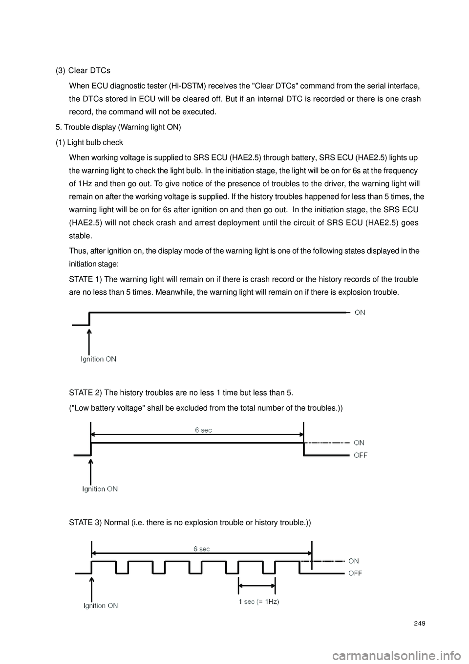
When working voltage is supplied to SRS ECU (HAE2.5) through battery, SRS ECU (HAE2.5) lights up
the warning light to check the light bulb. In the initiation stage, the light will be on for 6s at the frequency
of 1Hz and then go out. To give notice of the presence of troubles to the driver, the warning light will
remain on after the working voltage is supplied. If the history troubles happened for less than 5 times, the
warning light will be on for 6s after ignition on and then go out. In the initiation stage, the SRS ECU
(HAE2.5) will not check crash and arrest deployment until the circuit of SRS ECU (HAE2.5) goes
stable.
Thus, after ignition on, the display mode of the warning light is one of the following states displayed in the
initiation stage:
STATE 1) The warning light will remain on if there is crash record or the history records of the trouble
are no less than 5 times. Meanwhile, the warning light will remain on if there is explosion trouble.
STATE 2) The history troubles are no less 1 time but less than 5.
("Low battery voltage" shall be excluded from the total number of the troubles.))
STATE 3) Normal (i.e. there is no explosion trouble or history trouble.))
Page 258 of 392

251Section 2 TroubleshootingI. LIST OF TROUBLES1. SRS warning light OFFDIAGNOSTIC PROCEDURESWhen performing the first diagnostic check, it is advised to shake slightly the harness and connector to see if
there is any discontinuous poor contact in circuit. If there is such a problem, make sure that the connections
of the connector, terminals and wire harness are correct and undamaged. Otherwise, follow these procedures:
(1) Check other wire harnesses and instrument cluster indicator lights
1Turn the ignition switch ON.
2Any other light on?
Yes: turn the ignition switch to LOCK, and continue with the next step.
No: check the power supply and ground system (fuse) of the instrument cluster, and continue with step 5.
(2) Check light bulb
CAUTION:
Mishandling of SRS components may release unexpectedly airbag and seat belt pretensioner, probably lead-
ing to a serious accident. Read the service cautions before handling a SRS component.
1Turn the ignition switch to LOCK.
2Disconnect the negative (-) terminal cable from the battery and wait for at least 60s.
3Remove the instrument cluster.
4Measure and see if the two pins of the SRS warning light is triggered.
Yes: continue with next step.
No: replace the bulb of the warning light.
Trouble Che c king Status P ossible Ca use
·Loss of voltage (fuse c irc uit bre a k)
·Instrument cluster trouble
·Trouble of wire harness between instrument
cluster and ECU SRS warning light OFF SRS wa rning c ircuit trouble1 SRS warning light is OFF SRS wa rning c irc uit trouble. No. Trouble shooting Ite ms De sc ription
2 SRS warning light re mains on SRS wa rning circ uit trouble or exte rna l trouble.
Page 290 of 392
![GEELY CK 2008 User Guide 283II. Non-DTC Problem Inspection Table1 With ignition s witch ON (Engine Off),
the AB S warning lig ht do e s no t g o o nLike ly Caus e s[De s cription] ABS Wa rning Light doe s not go
on, th GEELY CK 2008 User Guide 283II. Non-DTC Problem Inspection Table1 With ignition s witch ON (Engine Off),
the AB S warning lig ht do e s no t g o o nLike ly Caus e s[De s cription] ABS Wa rning Light doe s not go
on, th](/img/58/57159/w960_57159-289.png)
283II. Non-DTC Problem Inspection Table1 With ignition s witch ON (Engine Off),
the AB S warning lig ht do e s no t g o o nLike ly Caus e s[De s cription] ABS Wa rning Light doe s not go
on, the like ly c a use ma y be the ope n in the
warning light powe r supply c irc uit, burne d bulb
or dama ged wa rning light drive module .�z Burned fuse
�z A B S W a r ning L ight B ulb bur ne d
�z Power supply circuit open
�z ABS Wa rning Light Drive Module da mage dCheck the ABS warning light
fuse in the fuse blockRemove the ECU connector,
does the warning light goes on
with the ignition switch ON? Check whether the ABS
warning light is burnedCheck whether the warn-
ing light power supply cir-
cuit and ground circuit in the
wire harness is openCheck the connector of the
warning light power supply
circuit and ground circuit in
the wire harness Does the fault reoccur?Abn.
Replace
Repair the wire harnessNo
Ye s
Abn.
Abn. Ok
Ye s No
Ok
OkReplace
Repair the wire
harness
Repair the connectorCheck whether the wire in the
ABS wire harness connecting
the ABS warning light drive
module and the ECU is short
to ground Ye s Replace the warning light
drive module Ye sNoRefer to "Occa-
sional Problem
Service Key Points"