service GEELY CK 2008 Workshop Manual
[x] Cancel search | Manufacturer: GEELY, Model Year: 2008, Model line: CK, Model: GEELY CK 2008Pages: 392, PDF Size: 38.86 MB
Page 6 of 392
Section 3 Removal & Installation................................................................................... 262Chapter 8 MK-20 ABS System........................................................................ 2 7 2Section 1 ABS Diagnosis ................................................................................................. 272
Section 2 ABS System Check .......................................................................................... 276
Section 3 Removal and Installation................................................................................. 292Part IV Air Conditioner and Inside & Outside Trim ......................297Chapter 1 A/C System...................................................................................... 2 9 7Section 1 The Structure & Working Principle of Refrigeration System...............................297
Section 2 Heating System ................................................................................................ 299
Section 3 A/C controlling system.................................................................................... 302
Section 4 Service Caution & Notice................................................................................ 304
Section 5 The Refrigeration System Operation Procedure..............................................305
Section 6 Basic System .................................................................................................... 308
Section 7 A/C System Faults Check & Troubleshooting................................................ 313Chapter 2 Inside & outside Trim and Accessory................................................318Section 1 Configuration Index............................................................................................318(I) Outside Trim And Front Accessory.................................................................................318
(II) Outside Trim and Rear Accessory.................................................................................319
(III) Front inside trim..........................................................................................................320
(IV) Rear inside trim ............................................................................................................321Section 2 Inside & Outside Trim and Accessories Removal and Installation.......................322(I) Front Bumper..................................................................................................................322
(II) Engine Hood.................................................................................................................324
(III) Outside Rear View Mirror
(IV) Rear trunk Lid...............................................................................................................327
(V) Rear Bumper...................................................................................................................329
(VI) Seat Removal, Installation and Adjustment...................................................................331
(VII) Seat Belt.....................................................................................................................335
(VIII) Instrument panel and auxiliary console.....................................................................338
(IX) A pillar inside trim and front door sill ............................................................................343
(X) B pillar inside trim........................................................................................................344
(XI) Cpillar inside trim and rear door sill.............................................................................345
(XII) Roof inside trim
(XIII) Carpet and Heat Insulator.............................................................................................347 ...............................................................................................326
...........................................................................................................346
Page 7 of 392
(XIV) Rear trunk Inside Trim............................................................................348
(XV) Engine Hood Inside Trim...........................................................................349
(XVI) Door..............................................................................................................350Part V Body............................................................................359Chapter 1 General Information.....................................................................359Section 1 Body Structure..............................................................................................359Chapter 2 Body Repair..................................................................................369Section 1 Body Damage Forms and Requirements for Repair....................................369
Section 2 Typical Technology Of Body Panel Repair..................................................372
Section 3 Repair after Body Damage..........................................................................372
Section 4 Features and Composition of Automobile Body............................................. 377
Section 5 Painting Technique after Body Repair............................................................383
Section 6 Service Data For Body................................................................................385
Page 14 of 392

76. Adjust intake valve clearance
(a) Detach intake camshaft
Notice:
Because the camshaft end play is quite small, keep camshaft horizontal when removing it. If not, cylinder
head may be partially damaged by the thrust force£¬it may stuck or damage camshaft when turning crankshaft.
Take the following steps to avoid the damage:
(1) Turn the pulley to access the hole on the camshaft drive gear where the counter gear is installed. See
(Figure 12).
Hint:
The above condition allows the cylinders No. 1 and No. 3 of the intake camshaft to push up the valve tappet.
(2) Remove bolt and bearing cap No. 1.
(3) Install camshaft counter gear to drive gear with service bolt. See (Figure 13).
(4) Uniformly loose and remove 8 bearing cap bolts in several passes as
shown in the figure. See (Figure 14).
(5) Remove 4 bearing caps and camshafts.Figure 11
Figure 14 Figure 12 Figure 13
Page 15 of 392

8Notice:Due to the small end play on camshaft, the cylinder head may be damaged by the thrust force when removingit, it may stuck or damage camshaft. Take the following steps to avoid damage: (1) Turn the crankshaft pulley to make exhaust camshaft dowel pin is a bit higher than the cylinder head. See(Figure 15). (2) Align the matchmark on each gear to engage intake camshaft gear and exhaust camshaft gear. See(Figure 16).
(3) When the gears are engaged, install the intake camshaft bearing onto bearing journal.
Hint:
The intake camshaft lobe of cylinder 1 and 3 can jack up their own valve tappet.
(5) Install 4 bearing caps to the right position.
(6) Apply a light layer of engine oil on the thread and under the head of bearing cap bolts.
(7) Uniformly install and tighten 8 bearing cap bolts in several times, in the sequence shown in the figure.
Torque: 13N. m
(8) Remove service screw.
(9) Install the bearing cap No. 1. in the direction of the forward arrow mark.
(10)Apply a light layer of engine oil on the thread and under the head of bearing cap bolts.
(11)Alternatively tighten and install 2 bearing bolts.
Torque: 13N. m
7. Adjust exhaust valve clearance. See (Figure 17)
Remove adjust gasket.
(1) Crank to keep the camshaft head upward.
(2) Face valve tappet nick to vehicle front. (3) Press valve tappet, put special tool between camshaft and valve tappet.Hint:
�zLean the end with mark "9" into the position in (Figure 18).Figure 15Install MarkTiming MarkMarch MarkCam LobeUpward
NickFrontFigure 17
Figure 18 Figure 16
Page 31 of 392

24(c) Loose installing bolt of the idler. See (Figure 52). Move the pulley to
its far left and tighten it temporarily.
(d) Remove the belt from the camshaft timing pulley.
Notice:
�zHold the timing belt, the engagement of the crankshaft timing
pulley and timing belt will not move.
�zBe careful not to drop anything into the timing belt cover.
�zDo not let the belt contact oils, water or dirt.
Figure 53
22. Remove the camshaft and the timing pulley. See (Figure 53)
(a) Turn the camshaft hexagon head and loose pulley bolt.
(b) Remove pulley bolt and timing pulley.
23. Remove camshaft. See (Figure 54)
Because the camshaft end play is quite small, keep camshaft horizontal
when removing it.Take the following steps to avoid the damage:
(a) Remove the camshaft
(1) Turn the camshaft to access the hole of the counter gear installed on camshaft drive gear.
Hint: The intake camshaft lobe of Cylinder 1 and 3 can push up their
own valve tappet.
(2) Remove 2 bolts and bearing cap No. 1.
(3) Install the counter gear on the intake camshaft with the service
bolt onto the drive gear.
(4) Uniformly loose and detach 8 bearing cap bolts in several times
in the sequence shown in Figure 55.
(5) Remove 4 bearing caps and camshaft.
If the camshaft can not be kept horizontal, lift it vertically. Reinstall the
bearing cap with 2 bolts. Alternatively loose and detach the bearing cap
bolts and lift the camshaft gear. See (Figure 56)Figure 52
Figure 55
Figure 56 Figure 54
Page 32 of 392

25 (b) Remove the counter gear of the camshaft.
(1) Clamp the camshaft's hexagon on the vise.
(2) Turn the counter gear cloclwise, Remove the service bolt.
(3) Remove the snap ring with a circlip pliers. See (Figure 57).
(4) Remove waved gasket, camshaft counter gear and the camshaft gear spring. See (Figure 58)
24. Remove and install spark plug hole gasket. See Provision 15 and 16, Section 3 Timing Belt
Replacement for detailed information. See (Figure 44, 45).
Figure 57
25. Install camshaft
(a) Install exhaust camshaft and turn camshaft counterclockwise to make the dowel pin cross the vertical
line a little. See (Figure 59).
(b) Apply grease to a new oil seal lip and install it into the oil seal. See (Figure 60).
Figure 59
(c) Install camshaft counter gear.
(1) Clamp the camshaft's hexagon head with a vise.
(2) Install camshaft gear spring, camshaft counter gear and waved washer. (Figure 61).
Hint: Align the pin on the gear to the spring end of the counter gear.
(3) Install the snap ring with a circlip plier.
(4) Turn the counter gear clockwise with the special tool. Align the
holes on the camshaft drive gear. Install the service bolt.Figrue 61Rotate
Figure 58
Figure 60
Page 71 of 392
64Chapter 9 General Engine Troubles and Their
TroubleshootingSection 1 Overview The wide application of the electronic technologies to the vehicles brings innovation on diagnosis of the
vehicle, many varieties of diagnosis instruments that are very effective and efficient for the vehicle diagnosis
are innovated. Once the fault occurs, the best choice is to go to service station for help. However, even the
most advanced instrument has its limit. For some faults, manual diagnosis is far more convenient and easier
than that of instrument. In case of the crack, distortion and leakage of the components, the manual diagnosis
is even superior to the instrument diagnosis. The faults occurred shall be carefully analyzed and troubleshot
in accordance with the repair manual for normal usage.Section 2 General Engine Fault and TroubleshootingI. Fuel pipeline and circuit fault causing the engine starting failureengine starting failure normally include: starter does not run or starter runs but fails to crank the engine, or
cranks the engine but cranks slowly; starter can crank but fail to start the engine. There are many causes that
result in starting failure, such as failures in starting system, ignition system, fuel injection system and engine
mechanical failure.
1. starter does not run or fails to crank the engine or cranks slowly
(1) Symptom: starter does not run or spongy rotation
(2) Causes:
b. Low battery voltage, excessive battery discharge, damaged generator or failure in charging circuit;
c. Battery terminal rust and backed out;
d. Failure in starting circuit, ECU can not receive STA signal;
e. Damaged starter.
2. engine can not start and crank
(1) Symptom
With the start switch on, starter can crank but fail to start the engine.
(2) Causes
a. Empty fuel tank;
b. Electrical fuel pump inoperative;
c. Injector inoperative;
d. Low fuel pressure;
e. Unreasonable starting operation;
f. Damaged throttle position sensor or no signal is sent to ECU due to the open in throttle position
sensor circuit;
Page 76 of 392

69j. Poor intake and exhaust valve seal, failed piston ring, low compression pressure;
h. Too many carbon deposit in spark plug and combustion chamber;
k. Water temperature switch and thermostat fault;
l. Aging of Oxygon sensor;
m. Incorrect ignition timing;
n. Check valve fault.
Figure 149Engine is difficult to start
Check whether the air cleaner is clogged Clogged
Troubleshooting
OK
Check the idle control valve NG
Repair or replace
OK
Check the fuel pressure Excessivly low
Service the electric fuel pump,
fuel filter and fuel pressure regulator
OK
Check the vacuum pressure sensor NG
Replace
OK
Check the water temperature sensor and intake air temperature sensor NG
Replace
OK
Check the start switch signal No
Service the start signal wire
OK
Check the ignition timing Misaligned
Adjust
OK
Check the cylinder pressure NG
Disassemble the engine
OK
Replace the ECU to retry
Page 77 of 392
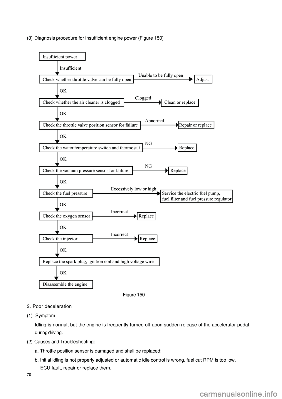
70(3) Diagnosis procedure for insufficient engine power (Figure 150)
2. Poor deceleration
(1) Symptom
Idling is normal, but the engine is frequently turned off upon sudden release of the accelerator pedal
during driving.
(2) Causes and Troubleshooting:
a. Throttle position sensor is damaged and shall be replaced;
b. Initial idling is not properly adjusted or automatic idle control is wrong, fuel cut RPM is too low,
ECU fault, repair or replace them.Insufficient power
Insufficient
Check whether throttle valve can be fully open Unable to be fully open
Adjust
OK
Check whether the air cleaner is clogged Clogged
Clean or replace
OK
Check the throttle valve position sensor for failure Abnormal
Repair or replace
OK
Check the water temperature switch and thermostat NG
Replace
OK
Check the vacuum pressure sensor for failure NG
Replace
OK
Check the fuel pressure Excessively low or high
Service the electric fuel pump,
fuel filter and fuel pressure regulator
OK
Check the oxygen sensor Incorrect
Replace
OK
Check the injector Incorrect
Replace
OK
Replace the spark plug, ignition coil and high voltage wire
OK
Disassemble the engineFigure 150
Page 78 of 392
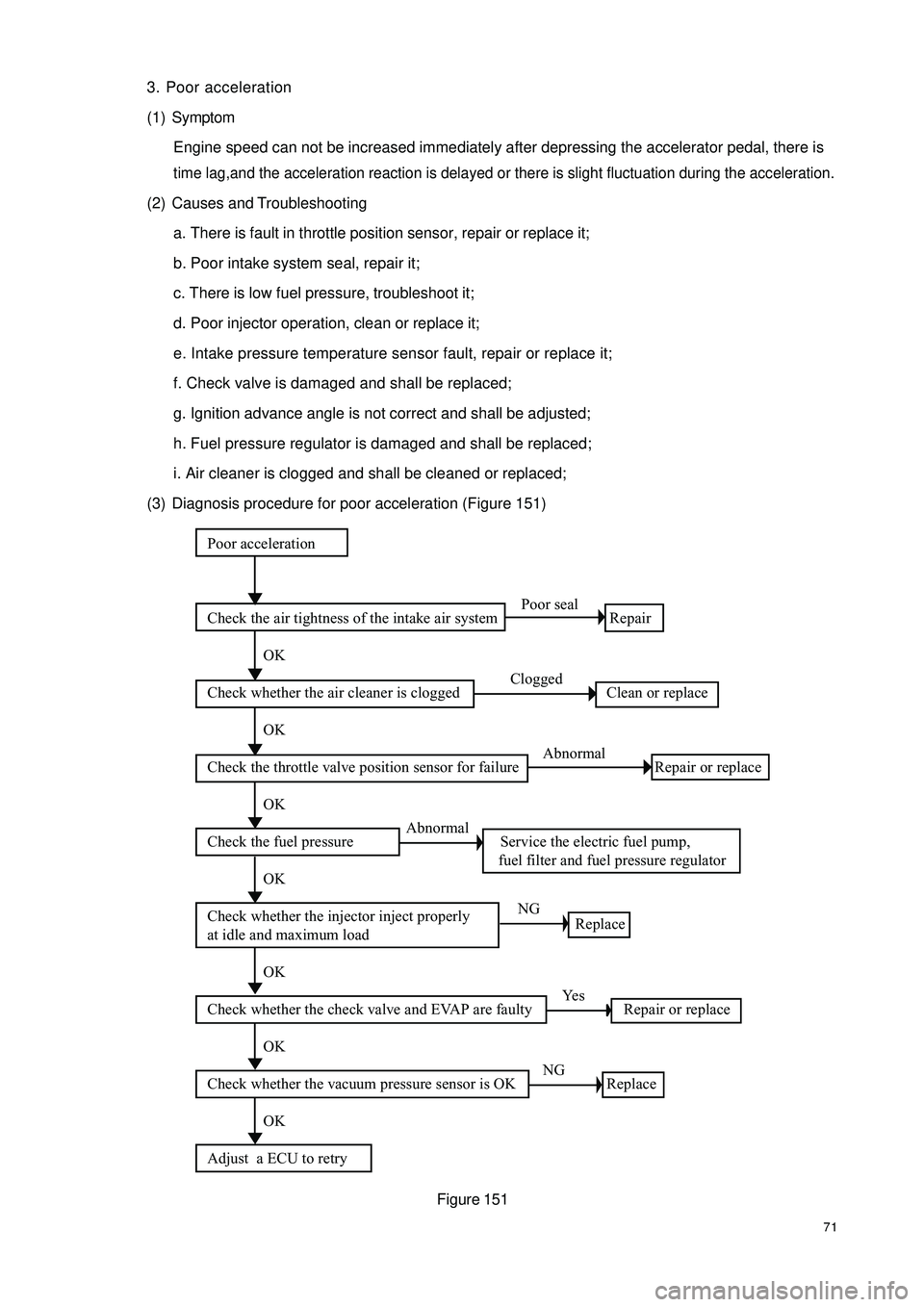
713. Poor acceleration
(1) Symptom
Engine speed can not be increased immediately after depressing the accelerator pedal, there is time lag,and the acceleration reaction is delayed or there is slight fluctuation during the acceleration.(2) Causes and Troubleshooting
a. There is fault in throttle position sensor, repair or replace it;
b. Poor intake system seal, repair it;
c. There is low fuel pressure, troubleshoot it;
d. Poor injector operation, clean or replace it;
e. Intake pressure temperature sensor fault, repair or replace it;
f. Check valve is damaged and shall be replaced;
g. Ignition advance angle is not correct and shall be adjusted;
h. Fuel pressure regulator is damaged and shall be replaced;
i. Air cleaner is clogged and shall be cleaned or replaced;
(3) Diagnosis procedure for poor acceleration (Figure 151)
Figure 151Poor acceleration
Check the air tightness of the intake air system Poor seal
Repair
OK
Check whether the air cleaner is clogged Clogged
Clean or replace
OK
Check the throttle valve position sensor for failure Abnormal
Repair or replace
OK
Check the fuel pressure Abnormal
Service the electric fuel pump,
fuel filter and fuel pressure regulator
OK
Check whether the injector inject properly
at idle and maximum load NG
Replace
OK
Check whether the check valve and EVAP are faulty Yes
Repair or replace
OK
Check whether the vacuum pressure sensor is OK NG
Replace
OK
Adjust a ECU to retry