clutch GEELY CK 2008 Owner's Manual
[x] Cancel search | Manufacturer: GEELY, Model Year: 2008, Model line: CK, Model: GEELY CK 2008Pages: 392, PDF Size: 38.86 MB
Page 309 of 392

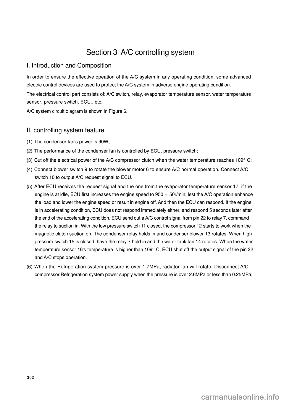
302Section 3 A/C controlling systemI. Introduction and CompositionIn order to ensure the effective opeation of the A/C system in any operating condition, some advanced
electric control devices are used to protect the A/C system in adverse engine operating condition.
The electrical control part consists of: A/C switch, relay, evaporator temperature sensor, water temperature
sensor, pressure switch, ECU...etc.
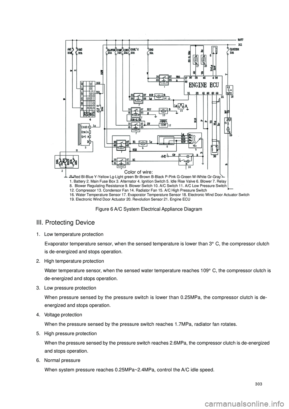
A/C system circuit diagram is shown in Figure 6.II. controlling system feature(1) The condenser fan's power is 90W;
(2) The performance of the condenser fan is controlled by ECU, pressure switch;
(3) Cut off the electrical power of the A/C compressor clutch when the water temperature reaches 109°C;
(4) Connect blower switch 9 to rotate the blower motor 6 to ensure A/C normal operation. Connect A/C
switch 10 to output A/C request signal to ECU.
(5) After ECU receives the request signal and the one from the evaporator temperature sensor 17, if the
engine is at idle, ECU first increases the engine speed to 950 ± 50r/min, lest the A/C operation enhance
the load and lower the engine speed or result in engine off. And then the ECU can respond. If the engine
is in accelerating condition, ECU does not respond immediately either, and respond 5 seconds later after
the end of the accelerating condition. ECU send out a A/C control signal from pin 22 to relay 7, command
the relay to suction in. With the low pressure switch 11 closed, the compressor 12 starts to work when the
magnetic clutch suction on. The condenser relay holds in and condenser blower 13 rotates. When high
pressure switch 15 is closed, have the relay 7 hold in and the water tank fan 14 rotates. When the water
temperature sensor 16's temperature is higher than 109°C, ECU shut off the output signal of the pin 22
and A/C stops operation.
(6) When the Refrigeration system pressure is over 1.7MPa, radiator fan will rotato. Disconnect A/C
compressor Refrigeration system power supply when the pressure is over 2.6MPa or less than 0.25MPa;
Page 310 of 392

303Figure 6 A/C System Electrical Appliance DiagramIII. Protecting Device1. Low temperature protection
Evaporator temperature sensor, when the sensed temperature is lower than 3°C, the compressor clutch
is de-energized and stops operation.
2. High temperature protection
Water temperature sensor, when the sensed water temperature reaches 109°C, the compressor clutch is
de-energized and stops operation.
3. Low pressure protection
When pressure sensed by the pressure switch is lower than 0.25MPa, the compressor clutch is de-
energized and stops operation.
4. Voltage protection
When the pressure sensed by the pressure switch reaches 1.7MPa, radiator fan rotates.
5. High pressure protection
When the pressure sensed by the pressure switch reaches 2.6MPa, the compressor clutch is de-energized
and stops operation.
6. Normal pressure
When system pressure reaches 0.25MPa~2.4MPa, control the A/C idle speed. Color of wire:R-Red Bl-Blue Y-Yellow Lg-Light green Br-Brown B-Black P-Pink G-Green W-White Gr-Gray
1. Battery 2. Main Fuse Box 3. Alternator 4. Ignition Switch 5. Idle Rise Valve 6. Blower 7. Relay
8. Blower Regulating Resistance 9. Blower Switch 10. A/C Switch 11. A/C Low Pressure Switch
12. Compressor 13. Condensor Fan 14. Radiator Fan 15. A/C High Pressure Switch
16. Water Temperature Sensor 17. Evaporator Temperature Sensor 18. Electronic Wind Door Actuator Switch
19. Electronic Wind Door Actuator 20. Revolution Sensor 21. Engine ECU
Page 317 of 392

3104. A/C Compressor Removal / Installation1. Disconnect the negative (--) terminal cable from the battery.
2. Drain the refrigerant from the system.
3. Detach the radiator.
4. Loose the drive belt and then remove the drive belt.Notice:•If anything moisture or any foreign matter enters into the Refrigeration system for circulation,
the cooling performance of the Refrigeration system will obviously deteriorate with abnormal
noise. Plug the port immediately after removing any cooling circulation component to prevent
anything moistur or any foreign matter from entering the circulation.5. Remove the compressor inlet and outlet pipe.
6. Removemagnetic clutch connector.
7. Remove the compressor.
8. The installation is in the reverse order of the removal.
9. Adjust the drive belt.
10. Check the Refrigeration system performance.5. The Condenser Removal / Installation1. Disconnect the negative (--) terminal cable from the battery.
2. Drain the refrigerant from the system.Notice:•If anything moisture or any foreign matter enters into the Refrigeration system for circulation,
the cooling performance of the Refrigeration system will obviously deteriorate with abnormal
noise. Plug the port immediately after removing any cooling circulation component to prevent
anything moistur or any foreign matter from entering the circulation.3. Remove the condenser inlet and outlet pipeline to prevent the compressor oil from splashing.
4. Remove condenser fan connector.
5. Remove the engine hood lock.
6. Remove the engine hood lock support brace.
7. Remove the condenser.
8. The installation is in the reverse order of the removal.
9. Check the Refrigeration system performance.The Condenser Installation Description:1. When installing the new condenser, it is recommended to fill certain SW-100 compressor oil into the
refrigerant circuit.Refill: (approximate)
20ml{20 cc }
Page 321 of 392

314Have a focus inspection on the following area:
a. Each pipe union joint and valve connection.
b. All hose, especially near the pipe union.
c. Compressor shaft seal, front and rear cover, gasket, oil fill plug.
d. Area on the surface of the condenser and evaporator that is scratched, bruised or damaged.
e. Expansion valve inlet and outlet connection and temperature sensor element and the welding position.
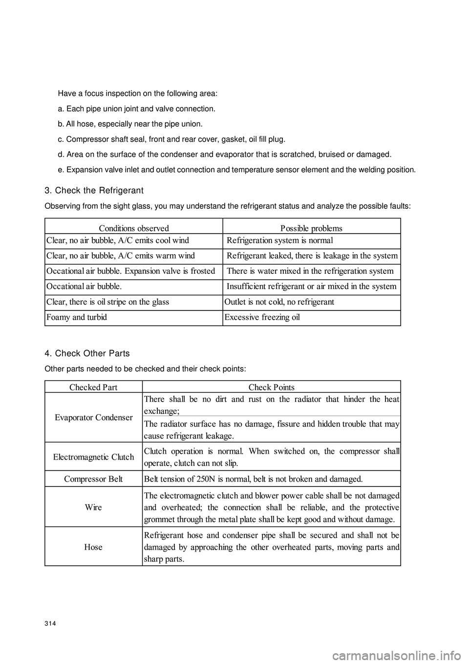
3. Check the Refrigerant
Observing from the sight glass, you may understand the refrigerant status and analyze the possible faults:
4. Check Other Parts
Other parts needed to be checked and their check points:Conditions obse rvedP ossible proble ms
Cle ar, no a ir bubble , A/C e mits c ool wind Re frige ra tion system is normal
Cle ar, no a ir bubble , A/C e mits warm wind Re frige ra nt le a ke d, the re is le aka ge in the syste m
Occ a tiona l a ir bubble . Expa nsion va lve is froste d There is wa te r mixe d in the re frigeration syste m
Occational air bubble. Insufficient refrigerant or air mixed in the system
Cle ar, the re is oil stripe on the gla ss Outle t is not c old, no refrige ra nt
Foamy and turbid Excessive freezing oilChecked PartCheck Points
The re sha ll be no dirt and rust on the radiator tha t hinde r the he at
exchange;
The ra dia tor surfa ce ha s no da mage , fissure a nd hidde n trouble tha t ma y
cause refrigerant leakage.
Elec tromagne tic Clutc hClutc h ope ration is norma l. Whe n switche d on, the c ompre ssor sha ll
operate, clutch can not slip.
Compre ssor Be lt Be lt te nsion of 250N is normal, belt is not broke n and dama ged.
WireThe electromagnetic clutch and blower power cable shall be not damaged
and overheated; the connection shall be reliable, and the protective
gromme t through the me tal plate sha ll be ke pt good a nd without da ma ge .
HoseRefrigerant hose and condenser pipe shall be secured and shall not be
dama ged by a pproac hing the othe r ove rhe ate d pa rts, moving pa rts a nd
sha rp parts. Eva pora tor Conde nse r
Page 323 of 392

316 Abnormal high pressure of the high pressure pipelineAbnormal low pressure of the high pressure pipeline Abnormal high pressure of the low pressure pipelineAbnormal low pressure of the low pressure pipelineHigh and low pressure can not be establishedSight glass has air bubble Compressor inlet side is frosted Compressor noise Abnormal heating on the compressorEvaporator is frostedDrier filter ices up A/C does not refrigerate or the cold air is insufficientD irt in t he evap orat or core, or
poor fit between the
exp ansion valve sensing unit
and evap orat or out letCheck and correct it
Non-evap orat ed refrigerant
steam enters into compressorService t he evap orat or and it s
comp onent s s uch as fan
exp ans ion valve op ening is
excessively big or faulty ,
refrigerant sup p ly is
exces s iveA djus t t he exp ans ion valve,
check t he s ens ing unit and t he
evap orat or out let for fit nes s ,
rep lace it as necess ary
××Exp ansion valve op ening is
too smallAdjust exp ansion valve
××××Exp ansion valve fault , sp inal
corrosion or leakageRep lace exp ans ion valve
×× ×T he refrigerant p ip eline
bet ween t he exp ansion valve
sensing unit and t he
exp ansion valve is damaged or
brokenCheck and rep lace t he
exp ansion valve and p ip eline
××Exp ansion valve blocked by
ice or dirtRecy cle t he refrigerant ,
remove and clean t he
exp ansion valve, use the
vacuum p ump t o drain t he
water in the system and then
refill t he refrigerant
× Refrigerant p ip eline blockedD is as s emble and check t he
part
× Comp ressor solenoid clutch,
bearing and p ulley w earCheck and rep lace concerned
worn p art s
×××××× Comp ressor reed is damaged,
exhaus t valve leaksCheck and rep lace t he
comp res s or
× Comp res s or inlet blocked Check and clean
× × D rive belt loos e or broken Rep lace or rep lace it
×Exces s ively low t emp erat ure
in t he vehicle comp art ment sAdjust the selection switch
× × × × Sy s t em p ip eline leaksCheck t he leak area, refill
p rop er amount of refrigerant × ×× Problem Symptom
Possible Cause T roubleshoot ing
××
Page 354 of 392

347(XIII) Carpet and Heat InsulatorCarpet and Heat Insulator Diagram
Carpet and Heat Insulator Diagram
1. Carpet 2. Cowl Lower Sound Insulator 3. Cowl Upper Sound Insulator 4 . Cowl Outer
Panel Heat Insulator 5. Foot Pedal 6. Cross Pan Head Screw 7. Floor Sound Insulator
1. Removal
1Remove the front and rear seats, left front door sill, right front door sill, right B pillar lower inside trim, left
B pillar lower inside trim, right rear door sill, left rear door sill, front and rear part of the auxiliary console;
2Remove the cross pan head screw and remove the foot pedal.
3Remove carpet and cowl lower sound insulator, cowl upper sound insulator, cowl outer panel heat insulator.
2. Installation
1Install the accelerator pedal assembly, brake and clutch pedal assembly, parking brake control mechanism
assembly onto the vehicle body;
2Install the carpet to the corresponding hole. Install both sides of the carpet under the left front door sill,
right front door sill, right B pillar lower inside trim, left B pillar lower inside trim, right rear door sill, left
rear door sill.1 27 3
4
65