steering GEELY CK 2008 Owner's Manual
[x] Cancel search | Manufacturer: GEELY, Model Year: 2008, Model line: CK, Model: GEELY CK 2008Pages: 392, PDF Size: 38.86 MB
Page 110 of 392
103Chapter 5 Front Suspension SystemSection 1 Front Suspension SystemDescription on front suspension structure
This model uses strut swing arm independent suspension with stabilizer bar.
The shock absorber upper end is flexibly connected to the body through the shock absorber mounting seat,
the lower end is rigidly connected to the steering knuckle. The coil spring encloses the shock absorber (coil
spring geometrical axial line does not coincide with that of the shock absorber piston rod), and is supported
between the upper and lower spring seats.
Both ends of the stabilizer bar are connected to the shock absorber through the strut bar ball pin and the
intermediate part is supported on the lower front body by the rubber bushing and support frame.
The front cushion sleeves the shock absorber piston rod head to restrict the wheel jump limit position and
plays the role of buffer.
The thrust ball bearing, installed between the spring upper seat and the shock absorber mount, is used for the
relative rotation upon steering of the shock absorber rigidly connected to the steering knuckle to the shock
absorber mount flexibly connected to the body.
"L" type lower swing arm is secured to the lower engine compartment with the press plate through elastic
rubber bushing and hinge, and its outer end is connected to the steering knuckle through the ball stud pin
which is attached to the lower swing arm by 3 high intension bolts. The ball stud pin can be removed and
replaced when it is worn.
The ball seat material is saturated polyester containing oil, featured in comparatively high intensity and
wearability and good self-lubrication performance. Proper amount of grease has been added during the
assembly and there is no need for additional filling during the normal operation.
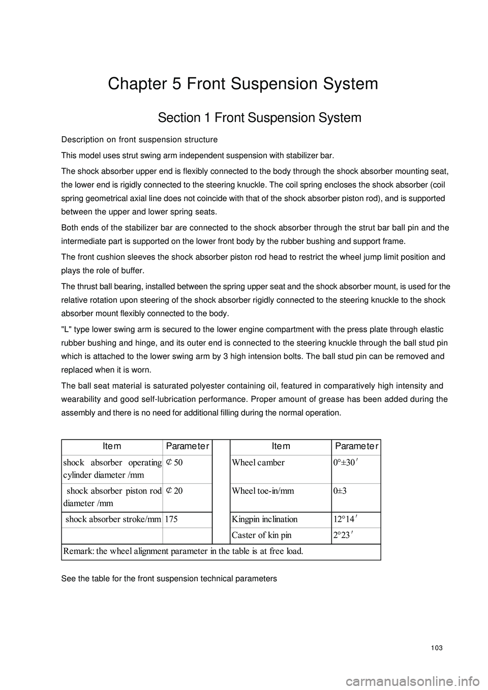
See the table for the front suspension technical parametersItem Parameter Item Parameter
shoc k a bsorbe r ope ra ting
cylinder diameter /mm¢
50 Wheel camber 0°±30′
shoc k a bsorbe r piston rod
diameter /mm¢
20 Wheel toe-in/mm 0±3
shoc k a bsorbe r stroke /mm 175 Kingpin inc lina tion 12°14′
Ca ste r of kin pin 2°23′
Remark: the wheel alignment parameter in the table is at free load.
Page 111 of 392

104PROBLEM SYMPTOMS TABLEUse the table below to help you find the cause of the problem. The numbers indicate the priority of the likely
cause of the problem. Check each part in order. If necessary, replace parts.Sympto m Sus pe cte d Are a
1. Tires (Worn or imprope rly infla te d)
2. Wheel alignment (Incorrect)
3. Steering system joint(Loose or worn)
4. Hub be a ring (Worn)
5. Ste e ring ge a r (Out of adjustme nt or worn)
6. Suspe nsion pa rts (Worn or da ma ge d)
1. Ve hic le (Ove rloa de d)
2. Spring (stiffne ss not comply with or da ma ge )
3. Shoc k a bsorbe r (Worn)
1. Tire (Worn or imprope rly infla te d)
2. Stee ring linka ge (Loose or dama ged)
3. Sta bilize r ba r (Be nt or broke n)
4. Shoc k a bsorbe r (Worn or da mage d)
1. Tire (Worn or imprope rly infla te d)
2. T ir e ( D yna mic ba la nc e is not a s s pe c if ie d)
3. Shock a bsorber (Worn or da ma ge d)
4. Wheel alignment (Incorrect)
5. Ball stud pin (Worn or da mage d)
6. Hub be aring (Worn or da mage d)
7. Ste ering linka ge (Loose or worn)
8. Ste e ring ge a r (Out of adjustme nt or worn)
1. Tire (Worn or imprope rly infla ted)
2. Wheel alignment (Incorrect)
3. Shoc k a bsorbe r (Worn or da mage d)
4. Suspe nsion pa rts (Worn or da ma ge d) Abnormal tire wearDeviation
Body Desc ent
Sways
F r ont w he e l s himmy
Page 113 of 392
106Section 3 Front Wheel AlignmentAdjustment1. Inspect tire
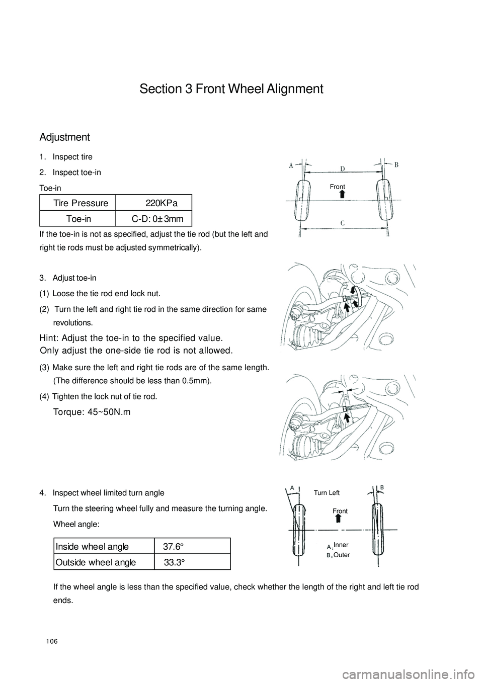
2. Inspect toe-in
Toe-in
If the toe-in is not as specified, adjust the tie rod (but the left and
right tie rods must be adjusted symmetrically).
3. Adjust toe-in
(1) Loose the tie rod end lock nut.
(2) Turn the left and right tie rod in the same direction for same
revolutions.
Hint: Adjust the toe-in to the specified value.
Only adjust the one-side tie rod is not allowed.
(3) Make sure the left and right tie rods are of the same length.
(The difference should be less than 0.5mm).
(4) Tighten the lock nut of tie rod.
Torque: 45~50N.m
4. Inspect wheel limited turn angle
Turn the steering wheel fully and measure the turning angle.
Wheel angle:
If the wheel angle is less than the specified value, check whether the length of the right and left tie rod
ends.Tire Pressure 220KP a
Toe-in C-D: 0±3mmInside whe e l a ngle 37.6°
Outside whee l a ngle 33.3°FrontFrontTurn Left Inner
Outer
Page 115 of 392

108Replacement1. Remove the front wheel.
2. Remove the ABS sensor from the steering knuckle. Separate the sensor and signal wire from the wire
harness bracket on the front shock absorber.
3. Separate the front brake hose
Remove 2 clips and separate the front brake hose from the front shock absorber bracket.
4. Remove the stabilizer bar link rod assembly
Remove the nut connecting the stabilizer bar link rod assembly and the shock absorber.
5. Remove the front shock absorber with the coil spring
(1) Remove the nuts and bolts connecting the shock absorber and brake.
(2) Remove the 4 nuts connecting the front shock absorber and vehicle body.
Notice: reliable object shall be used to support the brake assembly!
Page 119 of 392
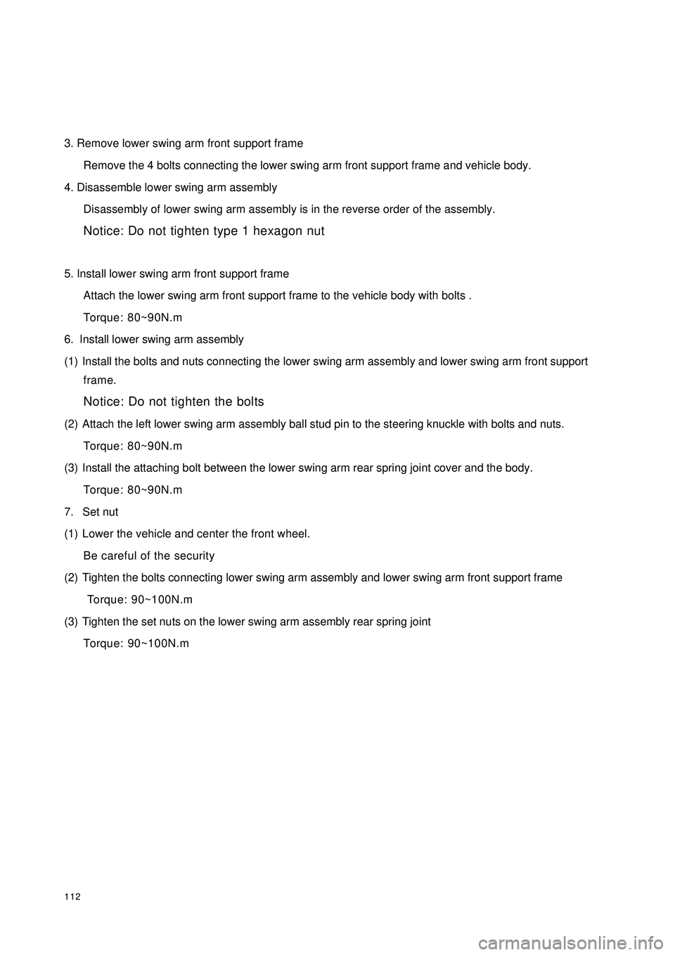
1123. Remove lower swing arm front support frame
Remove the 4 bolts connecting the lower swing arm front support frame and vehicle body.
4. Disassemble lower swing arm assembly
Disassembly of lower swing arm assembly is in the reverse order of the assembly.
Notice: Do not tighten type 1 hexagon nut
5. Install lower swing arm front support frame
Attach the lower swing arm front support frame to the vehicle body with bolts .
Torque: 80~90N.m
6. Install lower swing arm assembly
(1) Install the bolts and nuts connecting the lower swing arm assembly and lower swing arm front support
frame.
Notice: Do not tighten the bolts
(2) Attach the left lower swing arm assembly ball stud pin to the steering knuckle with bolts and nuts.
Torque: 80~90N.m
(3) Install the attaching bolt between the lower swing arm rear spring joint cover and the body.
Torque: 80~90N.m
7. Set nut
(1) Lower the vehicle and center the front wheel.
Be careful of the security
(2) Tighten the bolts connecting lower swing arm assembly and lower swing arm front support frame
Torque: 90~100N.m
(3) Tighten the set nuts on the lower swing arm assembly rear spring joint
Torque: 90~100N.m
Page 135 of 392

128Chapter 8 Power Steering SystemSection 1 Power Steering SystemPower Steering System DescriptionPower Steering System consists of the steering wheel, steering transmit device, power steering fixed device
and steering pipelines. The steering gear is rack and pinion type.
Major parameters for steering system:
Cautions:
1. Cautions for steering system
Make sure of the correct replacement of parts, incorrect replacement might affect the performance of
the steering system and lead to driving accidents.
2. Cautions for SRS System
This vehicle is equipped with SRS (Supplemental Restraint System), driver side air bag and front passenger
side air bag.
Failure to carry out service operations in the correct sequence could cause the unexpected deployment of
the air bag during servicing, possibly leading to a serious accident.Parameter
3.26
Inner 37.6°
Outer 33.3°
≤
10.5m Item
Steering Wheel total revolutions
Ma ximum Front
Wheel Turn Angle
Minimum Turning Dia me ter
Page 136 of 392
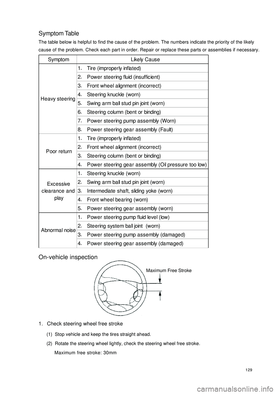
129Symptom TableThe table below is helpful to find the cause of the problem. The numbers indicate the priority of the likely
cause of the problem. Check each part in order. Repair or replace these parts or assemblies if necessary.On-vehicle inspection1. Check steering wheel free stroke
(1) Stop vehicle and keep the tires straight ahead.
(2) Rotate the steering wheel lightly, check the steering wheel free stroke.
Maximum free stroke: 30mmSymptom Like ly Ca us e
1.
Tire (imprope rly infla te d)
2.
P owe r ste ering fluid (insuffic ie nt)
3.
Front whe e l a lignme nt (inc orre c t)
4.
Ste e ring knuckle (worn)
5.
Swing a rm ba ll stud pin joint (worn)
6.
St e e r ing c olumn ( be nt or binding)
7.
P owe r ste ering pump a ssembly (Worn)
8.
Power steering gear assembly (Fault)
1.
Tire (imprope rly infla te d)
2.
Front whe e l a lignme nt (inc orre c t)
3.
St e e r ing c olumn ( be nt or binding)
4.
Power steering gear assembly (Oil pressure too low)
1.
Ste e ring knuckle (worn)
2.
Swing a rm ba ll stud pin joint (worn)
3.
Inte rmediate sha ft, sliding yoke (worn)
4.
Front whe e l be a ring (w orn)
5.
P owe r ste ering ge a r asse mbly (worn)
1.
P owe r ste ering pump fluid leve l (low)
2.
St e e r ing s ys t e m ba ll joint ( w or n)
3.
Power steering pump assembly (damaged)
4.
Power steering gear assembly (damaged) He avy ste eringPoor returnExcessive
clearance and
play
A bnor ma l nois eMaximum Free Stroke
Page 137 of 392

130Section 2 Steering Drive and Control MechanismComponentsSteering Wheel AssemblyAir Bag Assembly
Lower Cover Upper CoverHead Light
Dimmer SwitchCombined Switch Bracket
Nut
Dust CoverSteering Column AssemblyWiper Switch Assembly
Press Plate of Dustcover
Universal JointIntermediate Shaft
Page 138 of 392

131Replacement1. Cautions (refer to Steering System Cautions)
2. Make sure the wheels are placed straight ahead
3. disconnect the battery negative terminals
4. Remove the air bag assembly
Remove two screws on both sides and pull out the wiring harness connector
Notice: Do not pull air bag wire harness when removing the air bag assembly!
Warning:
�‹ �‹�‹ �‹
�‹Make sure the upper surface of the air bag assembly is kept upward when placing it!
�‹ �‹�‹ �‹
�‹Do not disassemble the air bag assembly!
5. Remove steering wheel assembly
(1) Remove the nut.
(2) Remove the steering wheel cover set bolt.
(3) place the matchmarks on the steering wheel and main shaft assembly.
(4) Use special tool to remove the steering wheel assembly.
6. Remove the steering column upper and lower cover
(1) Remove 3 screws.
(2) Remove the steering column upper and lower cover.Use Inner
Hex Socket
Wrench
Page 139 of 392
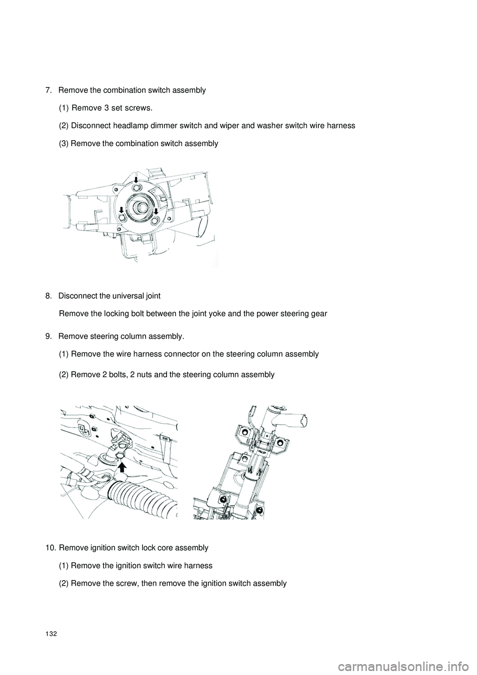
1327. Remove the combination switch assembly
(1) Remove 3 set screws.
(2) Disconnect headlamp dimmer switch and wiper and washer switch wire harness
(3) Remove the combination switch assembly
8. Disconnect the universal joint
Remove the locking bolt between the joint yoke and the power steering gear
9. Remove steering column assembly.
(1) Remove the wire harness connector on the steering column assembly
(2) Remove 2 bolts, 2 nuts and the steering column assembly
10. Remove ignition switch lock core assembly
(1) Remove the ignition switch wire harness
(2) Remove the screw, then remove the ignition switch assembly