ECO mode GEELY CK 2008 Workshop Manual
[x] Cancel search | Manufacturer: GEELY, Model Year: 2008, Model line: CK, Model: GEELY CK 2008Pages: 392, PDF Size: 38.86 MB
Page 92 of 392

85Part II ChassisChapter 1 Transmission Control DeviceSection 1 Transmission Control DeviceDescription on Transmission Control DeviceThis model is equipped with lever and cable transmission control devices, respectively used for 1.3L and 1.5L
engine, both of their gears are: 5 forward gears + 1 reverse gear.PROBLEM SYMPTOMS TABLEUse the table below to help you find the cause of the problem. The numbers indicate the priority of the likely
cause of the problem. Check each part in order. If necessary, replace these parts.Section 2 Lever Type Transmission Control DeviceComponentsSymptom
1. Tra nsmission c ontrol de vic e se le ctor (position
changing) cable (improperly assembled)
2. Ca ble or rela te d pa rts worn
3. Ca ble a sse mbly (incorrec t)
4. T r a ns mis s ion ( f a ult y)
1. Transmission control device selector (position
changing ) cable (improperly assembled)
2. Ca ble or rela te d pa rts worn
3. Ca ble a sse mbly (incorrec t)
4. Transmission (faulty) Transmission out of gea r
Transmission shift difficultControl lever Assembly
Dust Proof Cover
Botton Panel
Assembly of body
Dust Proof Cover Retainer
Control Pull Rod AssemblySuspected Area
Page 133 of 392

126Chapter 7 WheelSection 1 Tire InspectionInspection1. Check the tires for appearance and proper inflation pressure.
Check for inflation pressure after the vehicle stops for over 15min.
2. Using a dial gauge, check the runout of tire.
The tire runout should be no more than 3.0mm
Notice
(1) You must use specified tire and special wheel rim provided by the authorized service
center, otherwise it may affect the normal safe running of the vehicle and even result in
accidents!
(2) If the wheel rim is damaged, you must go to the authorized service center for service and
replacement! Never use the wheel rim of any other model!
3. Changing tire position
It is recommended to change the tire for each 10000km driving. See the figure for where to change each
tire
4. Inspect wheel dynamic balance
The imbalance should be no more than 8.0g. Otherwise, there will be extra vibration and noise when
driving.Tire module Tire inflationpressure
(Kpa
)
175/65 R14 82H 220Front
Page 165 of 392

158III. CUSTOMER FAULT ANALYSISNOTES:
1. When the troubleshooting analysis is underway, make sure to confirm the fault symptom correctly. Re-
move kinds of suppositions in order to make an exact judgment. In order to find out what on earth the fault is,
it is extremely important to ask customers about the fault symptoms and the conditions when faults occurred.
2. The 5 items below are the key points to analyze. Those faults that were considered irrelevant and the
repair history, etc are sometimes helpful. Therefore, try your best to collect relevant information, and find out
the relationship between the information you collected and the present information, in order to make refer-
ence in troubleshooting.
Key points of the Customer fault analysis:
1Vehicle model, system name
2Date, time, frequency fault occurs
3 Pavement conditions
4Running performance, driving and weather conditions
5Fault symptomIV. FAULT SYMPTOM AND DTCSNOTES:
1. The diagnosis system of the Free Cruiser possesses many features. The first important feature is the DTC
Checking. Input a fault from the ECU signal circuit in the form of code, and store it into the ECU memory.
The other feature is Input Signal Inspection. Inspect if the signals from different switches are correctly
inputted into the ECU. These features can quickly narrow the range of troubleshooting, to make an efficient
troubleshooting analysis. In the model of Free Cruiser, the systems below all possess the diagnosis feature.
1EFI system
2 ABS system
3Supplemental Restraint System (SRS)
2. When a DTC is checked, the very important point is: make sure if the fault shown by a DTC still exists, but
is normal now. In addition, when checking the fault symptom, you must check if there is direct relationship
between the fault shown by the DTC and the fault symptom. Therefore, the DTC should be checked before
and after confirming the fault symptom in order to confirm the present conditions. If you do not do so, it is
possible to make some unnecessary troubleshooting analysis on normal systems in some certain circumstances,
thus making it more difficult to locate the fault or repair according to the fault. So, a DTC check should be
done by a normal procedure.
3. The procedure below shows how to make a troubleshooting analysis by checking a DTC and how to make
efficient use of DTC check. Then carefully check the result, make a troubleshooting analysis of the DTC and
a troubleshooting analysis of the symptom.
1Inspect DTC
2Record and clear all DTCs
3Confirm fault symptom
Page 243 of 392

236Abnormal:Repair or replace wire harness and connector
Normal:Check and replace radio assembly
11. Sound quality poor only when playing CD (Volume faint)
(1) Replace it with another CD and re-check
Normal: CD failure
Abnormal:Replace the disc box
(2) Replace the disc box
Normal:Box damaged
Abnormal:Check and replace radio assembly
12.CD sound jump
(1) Disc cleaning
�yIf the disc gets dirty, clean the disc by wiping the surface from the center to outside in the radial directions
with a soft cloth.
Notice:
Do not use a conventional record cleaner or anti--static preservative.
Standard: The fault is cleared.
Normal:The disc is dirty
Abnormal:Replace it with another CD and re-check.
(2) Replace it with another CD and re-check.
Standard: The fault is cleared.
Normal: CD failure
Abnormal:Check when it will happen
(3) Check when it will happen
�yCheck where sound jump will happen
Standard: Drive on bumpy road
Normal:Replace CD box
Abnormal:Compare with other vehicles of the same model
(4) Compare with other vehicles of the same model
�yCompare with other vehicles of the same model of no fault. Check for any difference when faulty
occurs.
Standard: No difference is found.
Normal:Make sure there is no difference
Abnormal:Check CD box installation
(5) Check CD box installation
�yCheck CD box installation
Page 256 of 392

249(3) Clear DTCs
When ECU diagnostic tester (Hi-DSTM) receives the "Clear DTCs" command from the serial interface,
the DTCs stored in ECU will be cleared off. But if an internal DTC is recorded or there is one crash
record, the command will not be executed.
5. Trouble display (Warning light ON)
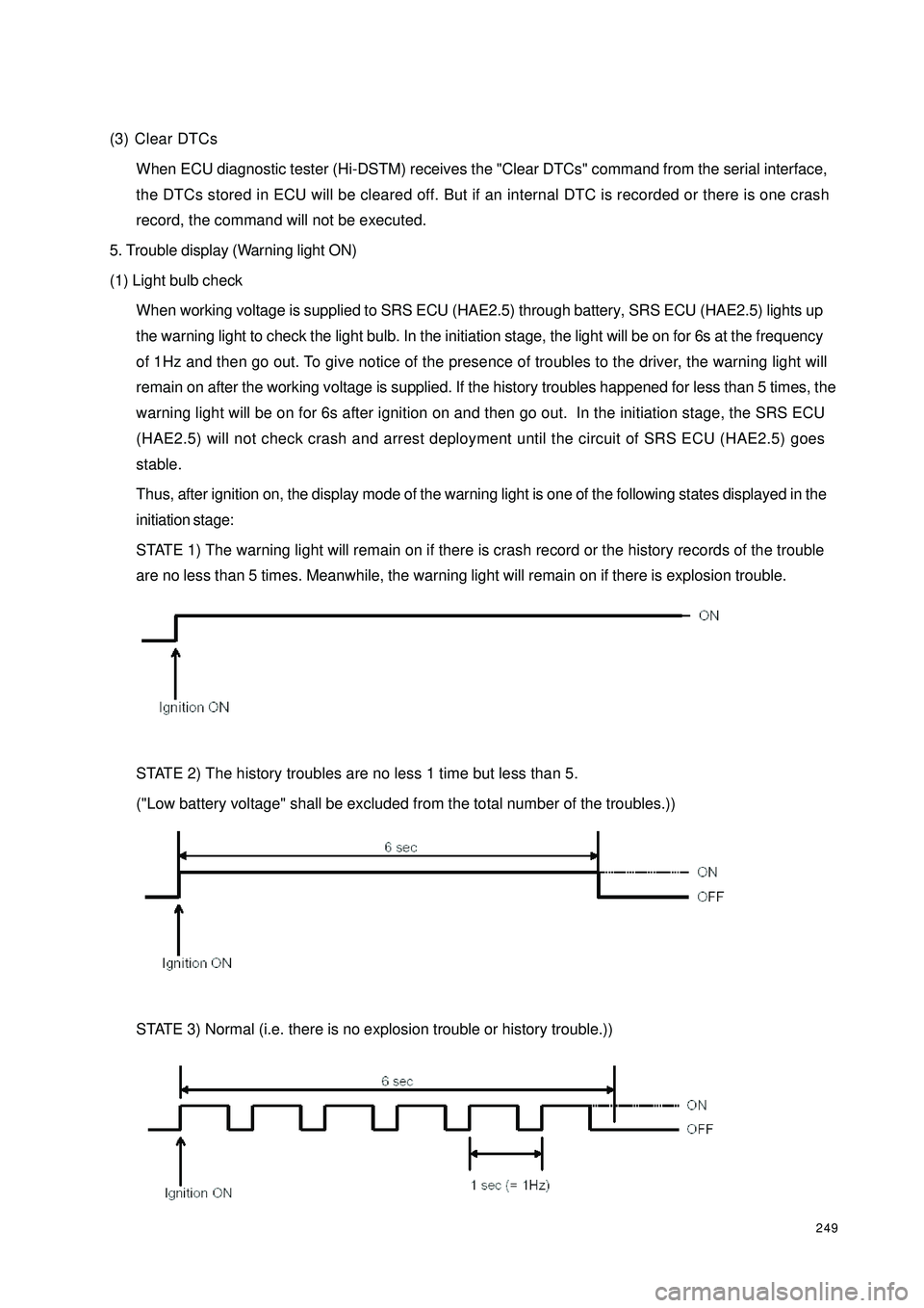
(1) Light bulb check
When working voltage is supplied to SRS ECU (HAE2.5) through battery, SRS ECU (HAE2.5) lights up
the warning light to check the light bulb. In the initiation stage, the light will be on for 6s at the frequency
of 1Hz and then go out. To give notice of the presence of troubles to the driver, the warning light will
remain on after the working voltage is supplied. If the history troubles happened for less than 5 times, the
warning light will be on for 6s after ignition on and then go out. In the initiation stage, the SRS ECU
(HAE2.5) will not check crash and arrest deployment until the circuit of SRS ECU (HAE2.5) goes
stable.
Thus, after ignition on, the display mode of the warning light is one of the following states displayed in the
initiation stage:
STATE 1) The warning light will remain on if there is crash record or the history records of the trouble
are no less than 5 times. Meanwhile, the warning light will remain on if there is explosion trouble.
STATE 2) The history troubles are no less 1 time but less than 5.
("Low battery voltage" shall be excluded from the total number of the troubles.))
STATE 3) Normal (i.e. there is no explosion trouble or history trouble.))
Page 303 of 392

296VII. Fill the liquid and bleedAfter replacing the HECU, bleed the second HECU circuit in addition to the filling and bleeding of the regular
brake system. Use the scan meter to perform the following procedure:Fill the fluid and bleed based on the regular brake system
until there is no air bubble in the transparent hoseConnect the scan meter with the diagnostic interfaceSelect function 04, Press OK button to confirmDepress the brake pedal and keep the hydraulic cylinder pushrod reboundRelease the brake pedal, loosen the left and right brake caliperbleeder screw, press "" buttonDepress the brake pedal 10 times, tighten the left and right
brake caliper bleeder screw, press "" buttonRepeat the above I II III steps 7 times and press "" buttonThe screen display the end of the bleed, press
"" button to return to "function selection" menuSelect function 06, Press OK button to confirm, quit the
diagnostic modeEnd →↑
↑
↑