ESP GEELY CK 2008 Workshop Manual
[x] Cancel search | Manufacturer: GEELY, Model Year: 2008, Model line: CK, Model: GEELY CK 2008Pages: 392, PDF Size: 38.86 MB
Page 92 of 392

85Part II ChassisChapter 1 Transmission Control DeviceSection 1 Transmission Control DeviceDescription on Transmission Control DeviceThis model is equipped with lever and cable transmission control devices, respectively used for 1.3L and 1.5L
engine, both of their gears are: 5 forward gears + 1 reverse gear.PROBLEM SYMPTOMS TABLEUse the table below to help you find the cause of the problem. The numbers indicate the priority of the likely
cause of the problem. Check each part in order. If necessary, replace these parts.Section 2 Lever Type Transmission Control DeviceComponentsSymptom
1. Tra nsmission c ontrol de vic e se le ctor (position
changing) cable (improperly assembled)
2. Ca ble or rela te d pa rts worn
3. Ca ble a sse mbly (incorrec t)
4. T r a ns mis s ion ( f a ult y)
1. Transmission control device selector (position
changing ) cable (improperly assembled)
2. Ca ble or rela te d pa rts worn
3. Ca ble a sse mbly (incorrec t)
4. Transmission (faulty) Transmission out of gea r
Transmission shift difficultControl lever Assembly
Dust Proof Cover
Botton Panel
Assembly of body
Dust Proof Cover Retainer
Control Pull Rod AssemblySuspected Area
Page 98 of 392

91Chapter 3 Clutch Control SystemSection 1 Clutch Control SystemClutch operating system descriptionThis model is equipped with hydraulic and cable clutch control system, respectively used for 1.3L engine
1.5L engine.PROBLEM SYMPTOMS TABLEUse the table below to help you find the cause of the problem. The numbers indicate the priority of the likely
cause of the problem. Check each part in order. If necessary, replace these parts.Section 2 Clutch Cable Control MechanismComponentsSympto m Sus pe cte d Are a
1. Clutc h pe da l position (Too low)
2. Control mec ha nism (Stagna tion)
3. Clutc h pe da l fre e stroke (too la rge)
C lut c h doe s not r e le a s e 1. H ydr a ulic pipe line ( A ir in line )
1. Control system (Incorrect assembly & adjustment)
2. Clutc h asse mbly (Fa ulty) Clutch noisyC lut c h s lipsConnect The
Clutch Fork Clutch Cable
Assmbly
Adjusting NutCowl Baffle
Clutch and Brake
Pedal Assembly
Page 177 of 392

170(b) Inspect the stator winding
1Inspect the resistance of the stator winding
Place the multimeter at R x 1, connect 2 pens of the
meter to any of the 2 pens wires of the armature winding
respectively. There must be continuity. Where the
resistance reading is infinitely great shows an open circuit.
2Inspect the winding ground
Place the multimeter at R x 1, connect one pole of the
meter to the pole wires of the armature winding
respectively and the other pole of the meter to the stator
core. If the resistance reading is infinitely great, the
armature winding is well-insulated. If not, it needs repairing
and replacing.IV. ALTERNATOR ASSEMBLY REPLACEMENT (MR479Q, MR479QA, MR481QA)(a) Disconnect the alternator connector.
(b) Loosen the Bolt A, B, C
(c) Loosen the V-belt. Then remove the alternator.
2. INSTALL ALTERNATOR ASSEMBLY
Torque:
M10 bolt 15N.m (154kgf.cm, 9ft.lbf)
Tension adjustment for V-belt:
When the center of the belt receives a 50N of downward pressure, there is a 10 mm of deflection.AlternatorInspection of Armature Winding Ground
Page 193 of 392

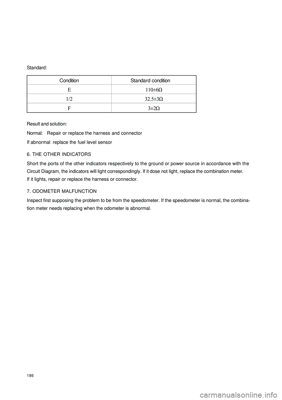
186Standard:
Result and solution:
Normal:Repair or replace the harness and connector
If abnormal replace the fuel level sensor
6. THE OTHER INDICATORS
Short the ports of the other indicators respectively to the ground or power source in accordance with the
Circuit Diagram, the indicators will light correspondingly. If it dose not light, replace the combination meter.
If it lights, repair or replace the harness or connector.
7. ODOMETER MALFUNCTION
Inspect first supposing the problem to be from the speedometer. If the speedometer is normal, the combina-
tion meter needs replacing when the odometer is abnormal.Condition Standa rd condition
E 110±6Ω
1/2 32.5±3Ω
F3±2Ω
Page 203 of 392

196Section 2 Replacement and AdjustmentI WIPER MOTOR ASSEMBLY REPLACEMENT1. REMOVE WIPER MOTOR
(a) Disconnect the connector.
(b) Remove the 4 mounting bolts.
(c) Separate the shaft of the motor crankshaft arm and the wiper link with special tools.
2. INSTALL A NEW WIPER MOTOR
(a) Press the shaft of the motor crankshaft arm and the wiper link in its position with special tools.
(b) Lock the 4 bolts in the specified torque.
(c) Connect the connector.
(d) Operate the wiper, make the washer fluid spraying on the windshield, check if the operation of wiper and
its starting position is normal. If not, remove the wiper arm blades assembly and make some proper
adjustment.
Hint: Make the top of the new shaft of the wiper motor crankshaft arm filled with lubricating oil.II. WIPER BLADES REPLACEMENT1. REMOVE BLADES FROM WIPER BLADES ASSEMBLY 1, 2
�yRemove blades from wiper blades assembly 1, 2 respectively.
2. INSTALL NEW BLADES
�yInstall new blades on wiper blades assembly 1, 2 respectively.4 Mounting Bolts
Page 257 of 392

250(2) Trouble indication
1In case of a trouble, the warning light will indicate. If the external trouble is a history trouble, the indication
will be cancelled. When the history trouble happens for no less than 5 times, the indicator light will remain
on even if there is no more trouble. "Low battery voltage" shall not be counted in the total number of
troubles.
2Only a service worker can reset a displayed or history trouble. The internal troubles of a SRS ECU
(HAE2.5) or the "crash record" of a trouble cannot be reset, in which case the SRS ECU (HAE2.5) shall
be replaced.
(3) Microcontroller-independent warning light on
Microcontroller with definitive troubles cannot fulfill its functions, thus cannot control the warning light. In
this case, the warning light will light up through proper circuit regardless of the microcontroller as stated
below:
�yMalfunction of the battery supplying power to SRS ECU (HAE2.5): the warning lights are turned
on continuously by means of the drive function of the selfcheck light.
�yLoss of internal working voltage: the warning light remains on.
�yReset due to trigger failure of the watchdog: the warning light blinks.
�yMicrocontroller out of work: the warning light always lights up.
�yIncomplete insertion of SRS ECU (HAE2.5) connector: the warning light remains on by means of
a shorting bar.
The diagnostic procedures can well be illustrated as follows:
If it is found that the SRS warning light remains on, follow the undermentioned procedures to check even if
the light goes out eventually. First, a scan meter is used to check the location of the trouble.
Then£¬go on with the checking in accordance with specific methods and procedures for the correspondent
location.
a. If the result indicates that it is an internal trouble or that the SRS is already detonated, replace the
ECU directly.
b. Troubleshooting.
Page 262 of 392

255(3) Check the wire harness between the fuse box and the connector of the SRS unit
CAUTION
If it is not handled properly, the airbag assembly may be triggered and deployed, leading to serious injury to a
person. Therefore, prior to handling, read the service cautions carefully. See service cautions for SRS.
1Turn the ignition switch to LOCK.
2Loosen the negative (-) terminal cable from the battery and wait for over 1 minute.
3Remove steering column hood.
4Loosen the connector of the clock spring.
5Remove glove box (along with passenger airbag assembly)
6Loosen passenger airbag assembly connectors.
7Remove left trim plate.
8Loosen all the SRS unit connectors.
9Reconnect the negative (-) terminal cable of the battery and turn ignition switch ON, check whether the
electrical potential between pins 5 and 6 (ground) of the connector of SRS unit is higher than 9V.
Yes: continue with next step.
No: replace the wire harness.
�VTurn the ignition switch to LOCK. 11 Loosen the negative (-) terminal cable from the battery and wait for over 1 minute. 12 Remove left trim plate. 13 Disconnect the adaptor connector of SRS unit. 14 Reconnect the battery negative (-) terminal cable and turn the ignition switch ON, check whether the
voltage between the corresponding pin of the connector and the pin (ground) is higher than 9V.
Yes: completion of trouble diagnosis.
No: replace the wire harness.
5. Driver side troubleDTC
B1 346
B1 347
B1 348
B1 349
CAUTION
● If it is not handled properly, the airbag assembly may be triggered and deployed,leading to s erious injury to a person. Therefore, prior to handling, read the service cautionscarefu lly .
See s erv ice cau t io n s fo r SRS
If there is driver airbag
● The resistance between terminals of the SRS unit connectors is out of range.
The wire harness of the driver airbag of SRS is short or open circuited.
● Driv er airb ag as s emb ly tro u ble.
● Clock spring internal trouble.
● Trouble of the connector of the circuit between clock spring and SRS ECU.
● The wire harness between clock spring and SRS ECU is open or short-circuited.
● In co rrect in s ert io n o f t h e co n n ect o r o f t h e d riv er airb ag g en erat o r o f SRS. Driver airbag trouble (high or low resistance, short circuit, ground, etc.)
Ch e c kin g Co n d it io n s
Pos s ib le caus e
Page 280 of 392

273IV. DTC Display Method
V. HCU DiagnosisUse the scan meter to diagnose the Hydraulic Control Unit (HCU), select the "3 HCU diagnosis" in the
options and perform the following procedures.
* Perform the above step 2 - 8 test for each wheel in the following order LF RF LR RR.
* If the result of some one of the above steps is different from the normal result, it indicates that the
corresponding element fails the normal operation, please check the corresponding element.
* You can use “ESC” button to end the test to return the function menu in any place in the screen where
there is “return” displayed to return to the function menu.Code Displa ye d
Ne ve r ha ppe ne d be fore No DTC
Happened before Occasional DTC
Ne ve r ha ppe ne d be fore Non-occ a sional DTC
Happened beforeOccasional DTC and Non-
occasional DTC System P roblem
The re is no proble m current ABS
Warning Light does not light up)
The problem still e xists(
ABS
Wa rning Light goe s on)Step Action Screen Display Normal Result
1 HCU dia gnosis – hydra ulic pump te st P ump motor operate s
2 LF Wheel——Depress the brake pedal
3LF Whe e l—— norma lly ope n va lve
ope n, norma lly c losed va lve c lose d,
wheel locked?Wheel locked
4LF Whe e l—— norma lly ope n va lve
closed, normally closed valve closed,
wheel locked?Wheel locked
5LF Wheel — — normally open valve
close d, norma lly close d va lve open,
wheel can rotate freelyWheel can rotate freely, the
pe da l re bound, the c ylinde r
motor ope ra ting noise is a udible
6LF Whe e l—— norma lly ope n va lve
closed, normally closed valve closed,
wheel can rotate freelyWheel can rotate freely
7LF Wheel — — normally open valve
ope n, normally c lose d va lve close d,
wheel locked?Wheel locked, the pedal sag
slightly
8Release the brake
pe dal De pre ss and hold
the brake pedal→→→
Page 286 of 392
![GEELY CK 2008 Workshop Manual 279 4 DTC 00283, 00285,00287, 00290 Like ly Cause s
[De s cription]
When there is recognized open
or short circuit in the sensor, this DTC is set.
[Hint]
The likely c ause ma y be the poor
c onn GEELY CK 2008 Workshop Manual 279 4 DTC 00283, 00285,00287, 00290 Like ly Cause s
[De s cription]
When there is recognized open
or short circuit in the sensor, this DTC is set.
[Hint]
The likely c ause ma y be the poor
c onn](/img/58/57159/w960_57159-285.png)
279 4 DTC 00283, 00285,00287, 00290 Like ly Cause s
[De s cription]
When there is recognized open
or short circuit in the sensor, this DTC is set.
[Hint]
The likely c ause ma y be the poor
c onne ction of the sensor, short circ uit in the coil
or wire ha rne ss, or fault in the se nsor signa l
proce ssing c irc uit in the ABS ECU�z Ope n c irc uit in the se nsor c onne ctor or coil
�z Short circuit in the sensor coil
�z The se nsor c onne ctor or wire harne ss is short to
ground or powe r supply
�z Fault in the sensor signal processing circuit in the
ABS ECURepair the connectorCheck the sensor on each wheelRemove the ABS ECU connector, check
whether the resistances among the following
terminals is within the specification?
Standard:
1.0~1.3K
LF: 1-2K
RF: 19-20K
LR: 5-6K
RR: 22-23K Check the corresponding sensor connectorDoes the fault reoccur?Check the wire harness between the ECU and
the sensor Refer to "Occasional Prob-
lem Service Key Points"Replace the ABS ECU
Abn.
Abn. Normal
Normal
Normal
Ye s Normal Ω,
Ω,
Ω,
Ω,
Ω,
Page 309 of 392

302Section 3 A/C controlling systemI. Introduction and CompositionIn order to ensure the effective opeation of the A/C system in any operating condition, some advanced
electric control devices are used to protect the A/C system in adverse engine operating condition.
The electrical control part consists of: A/C switch, relay, evaporator temperature sensor, water temperature
sensor, pressure switch, ECU...etc.
A/C system circuit diagram is shown in Figure 6.II. controlling system feature(1) The condenser fan's power is 90W;
(2) The performance of the condenser fan is controlled by ECU, pressure switch;
(3) Cut off the electrical power of the A/C compressor clutch when the water temperature reaches 109°C;
(4) Connect blower switch 9 to rotate the blower motor 6 to ensure A/C normal operation. Connect A/C
switch 10 to output A/C request signal to ECU.
(5) After ECU receives the request signal and the one from the evaporator temperature sensor 17, if the
engine is at idle, ECU first increases the engine speed to 950 ± 50r/min, lest the A/C operation enhance
the load and lower the engine speed or result in engine off. And then the ECU can respond. If the engine
is in accelerating condition, ECU does not respond immediately either, and respond 5 seconds later after
the end of the accelerating condition. ECU send out a A/C control signal from pin 22 to relay 7, command
the relay to suction in. With the low pressure switch 11 closed, the compressor 12 starts to work when the
magnetic clutch suction on. The condenser relay holds in and condenser blower 13 rotates. When high
pressure switch 15 is closed, have the relay 7 hold in and the water tank fan 14 rotates. When the water
temperature sensor 16's temperature is higher than 109°C, ECU shut off the output signal of the pin 22
and A/C stops operation.
(6) When the Refrigeration system pressure is over 1.7MPa, radiator fan will rotato. Disconnect A/C
compressor Refrigeration system power supply when the pressure is over 2.6MPa or less than 0.25MPa;