pcv GEELY CK 2008 Workshop Manual
[x] Cancel search | Manufacturer: GEELY, Model Year: 2008, Model line: CK, Model: GEELY CK 2008Pages: 392, PDF Size: 38.86 MB
Page 11 of 392

4Table 3
CO HC Problems Causes
1. Fa ult
. Inc orre c t ignition timing
. Fouled, shorted or imprope rly cle aranc e of spa rk plug
2. Incorrect valve clearance
3. Le a ky inta ke & e xha ust valve s
4. Leaky cylinders
1. Air leaks
. PCV hoses, intake manifold
. Throttle body
. Brake booster circuit
2. Le a n mixture ga s c a using misfire
1. Clogged air filter
2. Clogge d P CV valve
. Faulty ECU
. Fa ulty fue l pre ssure regula tor
. Faulty water temperature sensor
. Faulty air compressor
. Faulty injectors
. Faulty throttle position sensor Normal
Low High
High HighRough idle
(Black smoke
from exhaust
pipe ) Rough idle Rough idle High
Page 30 of 392

231. Disconnect all connected wire harnesses and the cable on the engine and the vehicle body
2. Remove air filter assembly with hose
3. Disconnect oil pipe and water hose
4. Loose positive and negative cables of the battery
5. Detach propeller shaft
6. Loose left & right rear engine mounting bracket after hoisting the engine.
7. Disconnect all other connectors between the engine and the vehicle body.
8. Remove engine per "Provison 20, Section 2, Chapter 2"
9. Remove A/C compressor to crankshaft pulleyV-belt
10. Remove power steering pump V- belt
11. Remove water pump fan pulley
12. Disconnect ignition coil and high voltage cables
13. Remove cylinder head cover sub-assembly
14. Remove generator assembly
15. Remove cylinder head cover sub-assembly
(a) Disconnect generator wire joint.
(b) Disconnect generator circuit
(c) Disconnect A/C compressor switch connector.
(e) Open wires clips.
(f) Disconnect wire harness from the cylinder head cover.
(g) Disconnect 2 ventilation PCV hoses from cylinder head cover.
(h) Remove 4 screws, 4 seal gaskets, cylinder head and gasket.
16. Remove generator assembly. See (Figure 50)
17. Remove timing belt cover
18. Remove crankshaft gear or pulley cover sub-assembly
19. Put the piston on Cylinder 1 to TDC compression position.
(a) Turn crankshaft pulley. Align its notch to the timing mark "O" on the
timing belt cover.
(b) Check if the mark "K" on camshaft timing pulley is aligned to the
timing mark on the bearing cap. Turn crankshaft 360° if not.
20. Remove ignition coil assembly
21. Remove timing belt. See (Figure 51)
(a) Mark on the timing belt and the camshaft pulley. The mark on the
timing belt to the timing belt cover No. 1 should match.
(b) Remove rubber gasket from timing belt cover.Figure 50
Figure 51
Page 34 of 392

2731. Install timing belt cover
Torque: 9.3N. m
32. Install generator assembly
33. Install right engine mounting bracket. See (Figure 67)
34. Install cylinder head cover sub-assembly
(a) Install 2 ventilation PCV hoses to the cylinder head cover.
(b) Connect the generator wire.
(c) Install the wire clip.
(d) Connect A/C compressor switch connector.
35. Install water pump pulley
36. Install power steering pump V-belt
37. Install A/C compressor to crankshaft pulleyV-belt
38. Install generator V-belt
39. Install left & right rear mounting bracket of engine.
40. Install ignition coil and high voltage cable
41. Hoist the engine back into the compartment
42. Install propeller shaft
43. Install air filter assembly with hose
44. Install oil pipe and water hoses
45. Install left and right front tires.
46. Check engine oil for leakage
47. Install all the wire harnesses and the cables on the engine connected to car bodyFigure 67
Page 50 of 392

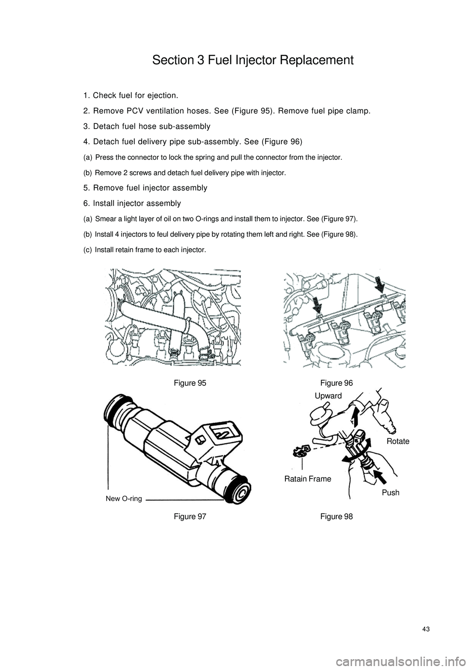
43Section 3 Fuel Injector Replacement1. Check fuel for ejection.
2. Remove PCV ventilation hoses. See (Figure 95). Remove fuel pipe clamp.
3. Detach fuel hose sub-assembly
4. Detach fuel delivery pipe sub-assembly. See (Figure 96)
(a) Press the connector to lock the spring and pull the connector from the injector.
(b) Remove 2 screws and detach fuel delivery pipe with injector.
5. Remove fuel injector assembly
6. Install injector assembly
(a) Smear a light layer of oil on two O-rings and install them to injector. See (Figure 97).
(b) Install 4 injectors to feul delivery pipe by rotating them left and right. See (Figure 98).
(c) Install retain frame to each injector.
Figure 95 Figure 96
Figure 97 Figure 98New O-ringUpward
Ratain Frame
PushRotate
Page 56 of 392

Near cylinder head
Cleaning pipeNear the intake manifold49(3) Check VSV operation from hole E to F and that the air flow should be difficult. See (Figure 114).
3. PCV sub-assembly
It should be easy for air to pass through the cylinder head.
Notice:
�zDo not suck air through valve.
�zNever put any object into the valve. Replace PCV if the operation is
not as specified.
�zBlow air in from the intake manifold side. Check that the air flow
should be difficult. Replace PCV if the operation is not as specified. See
(Figure 115).
Figure 115AirFigure 114