relay GEELY CK 2008 Workshop Manual
[x] Cancel search | Manufacturer: GEELY, Model Year: 2008, Model line: CK, Model: GEELY CK 2008Pages: 392, PDF Size: 38.86 MB
Page 48 of 392
41Chapter 4 Fuel System
(MR7131A, MR7151A, MR7161A)Section 1 Check Fuel System Pressure1. Remove the fuel tank from the vehicle
2. Check the fuel pump running
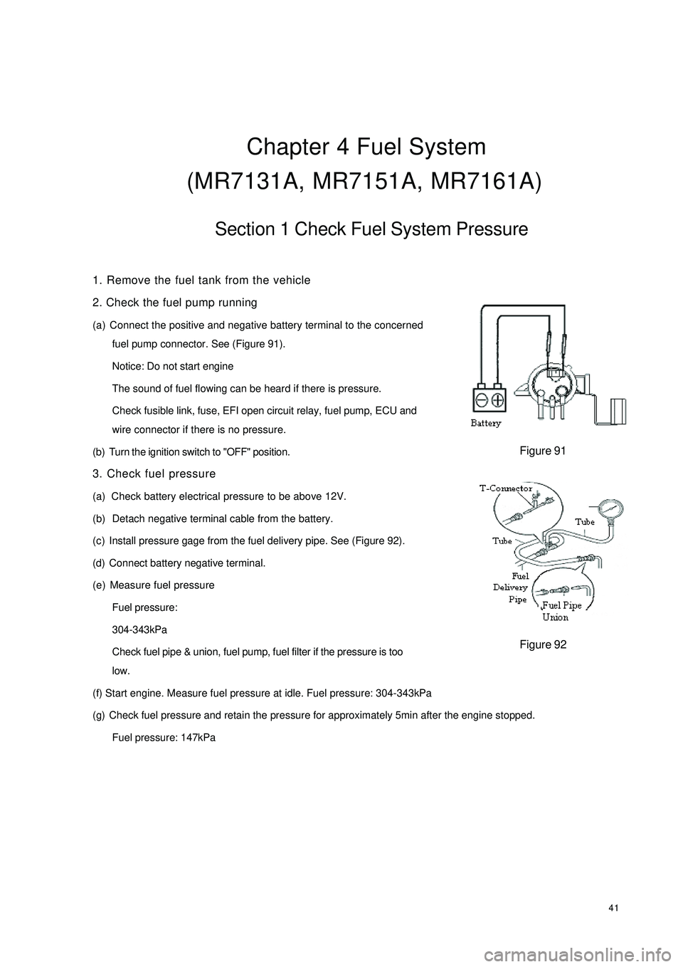
(a) Connect the positive and negative battery terminal to the concerned
fuel pump connector. See (Figure 91).
Notice: Do not start engine
The sound of fuel flowing can be heard if there is pressure.
Check fusible link, fuse, EFI open circuit relay, fuel pump, ECU and
wire connector if there is no pressure.
(b) Turn the ignition switch to "OFF" position.
3. Check fuel pressure
(a) Check battery electrical pressure to be above 12V.
(b) Detach negative terminal cable from the battery.
(c) Install pressure gage from the fuel delivery pipe. See (Figure 92).
(d) Connect battery negative terminal.
(e) Measure fuel pressure
Fuel pressure:
304-343kPa
Check fuel pipe & union, fuel pump, fuel filter if the pressure is too
low.
(f) Start engine. Measure fuel pressure at idle. Fuel pressure: 304-343kPa
(g) Check fuel pressure and retain the pressure for approximately 5min after the engine stopped.
Fuel pressure: 147kPaFigure 91Figure 92
Page 72 of 392
65g. Ignition system failure;
h. Low engine compression pressure.
(3) Diagnosis and Troubleshooting
a. First, check the fuel tank for fuel level, turn on the ignition switch, if fuel gauge pointer does not
move or fuel level warning lamp lights, then the fuel tank is empty, fuel shall be filled at this time.
b. Check that the electrical fuel pump for operation. Remove the fuel tank, you may use a wire to
connect the two jacks of the fuel pump for short, then turn on the ignition switch. The fuel pump
operation sound shall be able to be heard from the fuel tank nozzle or fuel flow can be felt with hand
pinching the tube; or remove the return hose on the fuel pressure regulator, check that the fuel
flows out; Direct judgment can be made if it is equipped with fuel pressure gage.
If electrical fuel pump is inoperative, check whether the main fuse, main relay, fuel pump relay,
fuel pump control circuit and ECU are OK. If all of them are OK, check fuel pump circuit for open,
short or damaged check valve. Repair or replacement shall be made when problems are found.
c. If there is no injection sound in injector, check injector control circuit for fault. You may use a
testing lamp with big resistance to be connected to the injector wiring connector, turn on the ignition
switch. If the testing lamp lights up, it indicates that the injector has been damaged and shall be
replaced; if the testing lamp does not light up, check whether the main fuse, EFI relay, fuse, ignition
switch and ECU terminal are OK, repair or replace them if they are not OK.
d. If there is low fuel pressure, the injection amount would be small and the engine won't start, you
should check the fuel filter for block and fuel pump safety valve for damage and check whether the
fuel pressure regulator is within the normal range, otherwise those components shall be repaired or
replaced.
e. Electric injection engine normally spot contact start the engine.
f. Check for open in the throttle position sensor (TPS) circuit.
g. Check whether there is Diagnostic Trouble Code (DTC), if there is, check it by the DTC; if there
is not, check the high voltage spark for intensity, if it is too weak, check spark plug, high voltage
wire, high voltage coil, distributor cover for faults, if there are faults, repair or replace them.
h. Check the compression pressure in the cylinder, insert the compression pressure gauge into the
spark plug hole, completely open the throttle, measure the compression pressure while starting the
engine. If the compression pressure is less than 980kPa when engine speed is more than 250r/min,
remove and inspect the engine and troubleshoot it.
3. The engine cranks but can not start
(1) Symptom
When starting the engine, starter can crank the engine but fail to start the engine.
(2) Causes:
a. Ignition advance angle is unfavorable;
b. Ignition is out of sequence, there is misfire;
c. High voltage spark is too weak;
d. The fuel pressure is too low;
e. fuel pressure regulator leakage;
Page 91 of 392
843. Output Level
ECU output level is designed to send control signal to the actuators of the electronic control system based on
the orders of the microprocessor in the micro-controller. The microprocessor control the output level by
controlling the occurrence position of the pulse, its length and duty ratio.
(1) Injection output level
The microprocessor controls the pulse length of the injection output level by making sure whether to
trigger to circuit or not in the injection output level.
(2) Ignition input level
The ignition output level is designed to amplify the ignition signal from the microprocessor into the primary
current of the ignition coil.
(3) Electric fuel pump output level
ECU microcontroller control the pump relay through electric fuel pump output level, and then control the
on and off of the electric fuel pump based on the current operating conditions.
(4) Other output levels
Control the output levels of the idle control valve, carbon canister solenoid valve, malfunction indicator
lamp. MR479Q, MR479QA, MR481QA engine idle control are closed loop control system, their injection
and ignition control are also closed loop control system.
Page 166 of 392
1594Make a simulation test in a way of symptom simulation
5Inspect DTC
6Confirm symptomV. SYMPTOM SIMULATIONNOTES:
The most difficult conditions to handle in the fault troubleshooting are that the fault symptom dose not appear.
Under the circumstances, make sure first to make a comprehensive analysis to the fault described by the
customer, then to simulate an environment that is similar or the same with the conditions when the fault of the
customer's vehicle occurred. No matter how rich the experience of the technician is and how skillful he is, if
he make a fault troubleshooting analysis without confirm the fault symptom, it is inevitable for him to neglect
some important factors and incorrectly guess, which may cause barriers to repair. For example, if a fault
occurs only when the engine is cool or if a fault occurs only caused by a vibration from pavement and so on,
when the engine is checked in the hot or static state, it is no way to confirm. Because of vibration, high-
temperature or seeping water (Vapor) often causes some faults that are difficult to reappear. So, here are
some effective symptom simulation tests.
KEY POINTS OF SYMPTOM SIMULATION TEST:
In the symptom simulation test, no doubt it is important to confirm the fault symptom, but the fault position or
fault components must be also found out. So, before the test and the pre-inspection of connection, narrow the
range of the circuit where faults may occur according to the fault symptom. Then make a symptom simula-
tion test to see if the circuit measured is normal; the fault symptom is also verified at the same time.
1. Way of Vibration: When vibration may be the major cause of the fault.
For example:
(a) Use your hand to gently vibrate the sensor that is considered the cause of the fault, in order to check if it
is ineffective.
(b) Softly rock the connector and harness in horizontal and vertical direction.
Notes: Hard rock may cause the relay circuit open.
2. Way of Spraying Water: When rainy weather or wet environment may be the major cause of the fault.
(a) Spray water on the vehicle to check if the fault occurs.
NOTES:
�yBe sure not to directly spray water into the engine compartment. Spray the water on the face of the
radiator to change the temperature and humidity indirectly.
�yBe sure not to spray water onto electronic devices and controllers.
Page 217 of 392
2108. REAR ROW READING LAMP ASSEMBLY
Inspect rear row reading lamp switch assembly continuity
Inspect continuity between the 2 terminals when the switch operates
If it is not as specified, replace the switch.
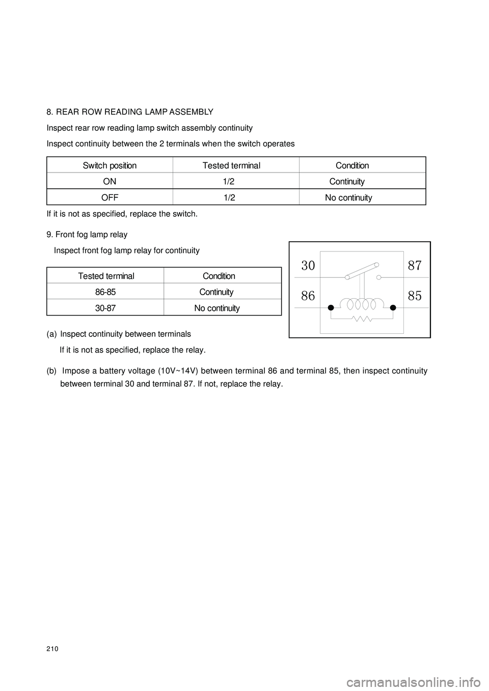
9. Front fog lamp relay
Inspect front fog lamp relay for continuity
(a) Inspect continuity between terminals
If it is not as specified, replace the relay.
(b) Impose a battery voltage (10V~14V) between terminal 86 and terminal 85, then inspect continuity
between terminal 30 and terminal 87. If not, replace the relay.S w it c h pos it ion T e s t e d t e r mina l C ondit ion
ON 1/2 Continuity
OFF 1/2 No continuityTe ste d te rmina l Condition
86-85 Continuity
30-87 No c ontinuity
Page 309 of 392
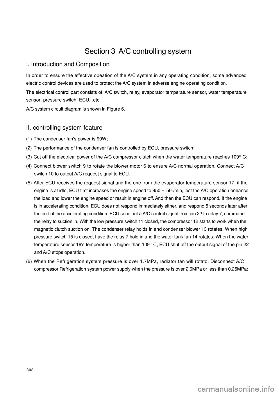
302Section 3 A/C controlling systemI. Introduction and CompositionIn order to ensure the effective opeation of the A/C system in any operating condition, some advanced
electric control devices are used to protect the A/C system in adverse engine operating condition.
The electrical control part consists of: A/C switch, relay, evaporator temperature sensor, water temperature
sensor, pressure switch, ECU...etc.
A/C system circuit diagram is shown in Figure 6.II. controlling system feature(1) The condenser fan's power is 90W;
(2) The performance of the condenser fan is controlled by ECU, pressure switch;
(3) Cut off the electrical power of the A/C compressor clutch when the water temperature reaches 109°C;
(4) Connect blower switch 9 to rotate the blower motor 6 to ensure A/C normal operation. Connect A/C
switch 10 to output A/C request signal to ECU.
(5) After ECU receives the request signal and the one from the evaporator temperature sensor 17, if the
engine is at idle, ECU first increases the engine speed to 950 ± 50r/min, lest the A/C operation enhance
the load and lower the engine speed or result in engine off. And then the ECU can respond. If the engine
is in accelerating condition, ECU does not respond immediately either, and respond 5 seconds later after
the end of the accelerating condition. ECU send out a A/C control signal from pin 22 to relay 7, command
the relay to suction in. With the low pressure switch 11 closed, the compressor 12 starts to work when the
magnetic clutch suction on. The condenser relay holds in and condenser blower 13 rotates. When high
pressure switch 15 is closed, have the relay 7 hold in and the water tank fan 14 rotates. When the water
temperature sensor 16's temperature is higher than 109°C, ECU shut off the output signal of the pin 22
and A/C stops operation.
(6) When the Refrigeration system pressure is over 1.7MPa, radiator fan will rotato. Disconnect A/C
compressor Refrigeration system power supply when the pressure is over 2.6MPa or less than 0.25MPa;
Page 310 of 392
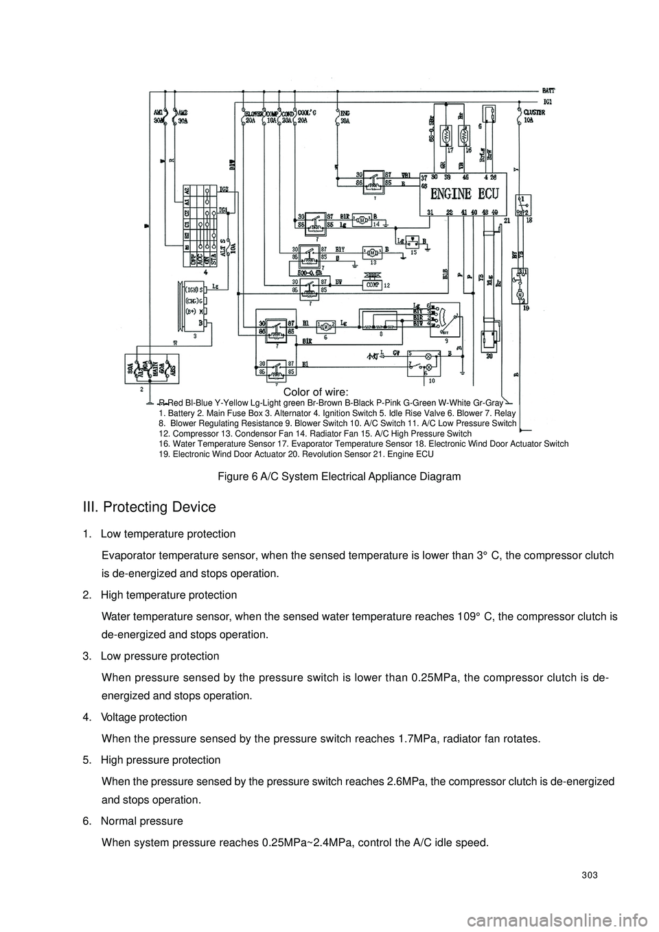
303Figure 6 A/C System Electrical Appliance DiagramIII. Protecting Device1. Low temperature protection
Evaporator temperature sensor, when the sensed temperature is lower than 3°C, the compressor clutch
is de-energized and stops operation.
2. High temperature protection
Water temperature sensor, when the sensed water temperature reaches 109°C, the compressor clutch is
de-energized and stops operation.
3. Low pressure protection
When pressure sensed by the pressure switch is lower than 0.25MPa, the compressor clutch is de-
energized and stops operation.
4. Voltage protection
When the pressure sensed by the pressure switch reaches 1.7MPa, radiator fan rotates.
5. High pressure protection
When the pressure sensed by the pressure switch reaches 2.6MPa, the compressor clutch is de-energized
and stops operation.
6. Normal pressure
When system pressure reaches 0.25MPa~2.4MPa, control the A/C idle speed. Color of wire:R-Red Bl-Blue Y-Yellow Lg-Light green Br-Brown B-Black P-Pink G-Green W-White Gr-Gray
1. Battery 2. Main Fuse Box 3. Alternator 4. Ignition Switch 5. Idle Rise Valve 6. Blower 7. Relay
8. Blower Regulating Resistance 9. Blower Switch 10. A/C Switch 11. A/C Low Pressure Switch
12. Compressor 13. Condensor Fan 14. Radiator Fan 15. A/C High Pressure Switch
16. Water Temperature Sensor 17. Evaporator Temperature Sensor 18. Electronic Wind Door Actuator Switch
19. Electronic Wind Door Actuator 20. Revolution Sensor 21. Engine ECU