service GEELY CK 2008 Owner's Guide
[x] Cancel search | Manufacturer: GEELY, Model Year: 2008, Model line: CK, Model: GEELY CK 2008Pages: 392, PDF Size: 38.86 MB
Page 299 of 392
292Section 3 Removal and InstallationI.Precautions for Removal1. Use the scan meter to locate the fault causes before proceeding to service.
2. wipe the surface clean with the cleaning agent without mineral oil before service; be careful to keep it
clean during service, only the lint-free cloth can be used to wipe the removed parts.
3. Only the original spare part can be used, and the package of the new spare part shall not be removed until
the installation.
4. Return liquid pump motor and the HCU is a type of integral structure and can not be separated.
5. When the system is opened, do not use compressed air or move the vehicle.
6. Use proper plug to clog each hydraulic outlet as soon as the ABS assembly is removed.
7. Remove other components that may interfere.
8. Please use the DOT 4 brake fluid, do not use the mineral oil.
9. Use the brake fluid to immerse the seal and the O ring, do not use the engine oil or brake grease.
10. After service, check the regular brake system and ABS brake function for normal and reliable operation.
11. Check all hydraulic pipe union for leakage.II. HECU Removal1. Turn off the ignition switch and disconnect the battery negative ground cable.
2. Remove the wire connector from the ABS HECU assembly.
3. Depress the brake pedal >60mm and hold it with the pedal retainer to close the master cylinder center
valve so that the brake fluid will not flow out from the outlet when the system is opened.
4. Put a clean cushion under the hydraulic regulator.
5. Remove the brake pipe (A, B) on the HCU connected to the master cylinder and place the mark, then
use a plug to clog the outlet immediately.
6. Remove the brake fluid pipe(1-4) leading to the wheels, then use a plug to clog the outlet immediately.
7. Remove the nut attaching the HECU to the bracket.
Page 311 of 392
304Section 4 Service Caution & NoticeI. Service CautionRefrigerant Treatment
•During the treatment, the operator shall be careful not to inhale A/C refrigerant or lubricant vapor. Long-
term exposure to the A/C environment will cause the operator's eye, nose and throat liable to stimulation.
In addition, based on the consideration on the environment influence, when discharging the HFC-134a
from the A/C system, we suggest using the recyclable and rechargeable devices. If sudden system fault
occurs, it is recommended to place the device on a ventilated place before starting service.
•For HFC-134a service equipment, it is recommended not to perform the pressurization check or leakage
inspection. If these mixture combust, it may result in severe human injury or property loss.
•Please be noticed not to let the refrigerant leak near the spark or other hot objects. If the refrigerant gas
contacts the spark or similar heat source (e.g. cigarette or heater), it may generate poisonous gas. The
refrigerant is extremely liable to leakage during the transportation. In this case, please eliminate or remove
the heat source mentioned above and keep good ventilation.
•It is very dangerous to handle the liquid refrigerant. Only a drop of refrigerant can result in local frostbite
on skin if dropped on the skin of the operator. Therefore, it is specified that the operator shall always
wear glove and eye protection during the handling of the liquid refrigerant. If liquid refrigerant gets in
your eyes or on your skin, Wash the area with much cool water. Go immediately to hospital for professional
treatment.
Refrigerant Preservation
• Refrigerant preservation container is a high pressure resistant equipment. If it is put in hot treatment, the
explosion may arise, and the resulting metal fragments and the splashed liquid refrigerant will result in
severe human injury. It is recommended to preserve the refrigerant below 40°C.II. Service NoticeInsufficient Refrigerant Handling
•If the refrigerant is founded to be insufficient during the fault diagnosis, it is recommended not to add
refrigerant because of the following facts: the pressure readings indicated by different pressure gauge
are different, thus you will be unable to determine the exact amount of the refrigerant to be added, and
excessive or insufficient refrigerant may cause a series of chained negative effects such as damaged
refrigerant circulation parts or deteriorated refrigeration effect. Therefore, if the refrigerant is found to
be insufficient, it is recommended to drain the refrigerant from the refrigerant circulation pipeline and fill
specified amount of the refrigerant.
Compressor Oil Handling
•For this type of vehicle, it is recommended to use SW-100 type compressor oil. Use of PAG compressor
oil other than the SW-100 type may cause the A/C compressor to be damaged.
•During the operation, please be noticed not to splash the SW-100 type compressor oil onto the vehicle
surface. Therefore, if this happens, please wipe it off immediately, otherwise the compressor oil will
damage the paint on the vehicle surface.
Page 313 of 392
3063. Check for leakage if the reading changes and vacuumize it again.
4. Refill the new HFC-134a refrigerant if the reading doesn’t change.
Fill the new HFC-134a refrigerant
1. Connect the intermediate pipe to the refrigerant steel jar.
2. Open the refrigerant steel jar valve.
3. Weigh the refrigerant steel jar to charge the right refrigerant volume (refrigerant refill 630g¡À20g).Warning:•Check for air leakage or any other leakage when refilling large amount of refrigerant into the
Refrigeration system. The operator is recommended to fill small amount of refrigerant first to
prevent the refrigerant from leakage, which will result in ozonosphere damage.•It is very dangerous to open the engine high pressure side valve if filling the refrigerant with
the service tank. The pressure in the service tank will rise during the operation, which will
result in the service tank explosion. The exploded mental fragment and the splashed refrigerant
will hurt the operator badly. Therefore, do close the high pressure side valve when the engine
is working.4. Open the manifold gauge low pressure side valve.
5. Close the manifold gauge low pressure side valve when the manifold gauge low pressure side reading is
increased to 0.098Mpa{1.0kgf/cm2}.
6. Check cooling pipeline/hose for leakage with leak detector.
•Proceed to step 8 if there is no leakage.
•Tighten the union joint if there is leakage at the loosened union joint and go to next step.
7. Re-check the leaked points.
•Go to next step if there is no leakage after tightening the union joint.
•If there is still leakage at the same union joint, drain refrigerant and repair the union joint. Repeat
the filling procedure and vacuum it.
8. Open the valve at the low pressure side of the manifold gauge. Fill the refrigerant until the refrigerant
tank weight from the one mentioned in Step 3 drop to 250g.
9. Close the valve at the low pressure side of the manifold gauge.
10. Start the engine and switch on A/C.
11. Open the valve at the low pressure side of the manifold gauge. Fill the refrigerant until the refrigerant
tank weight from the one mentioned in Step 3 to specified value.
12. Close the valve at the low pressure side of the manifold gauge and the valve of the refrigerant steel jar.
13. Stop the engine and A/C compressor.
Page 320 of 392
313Section 7 A/C System Faults Check & TroubleshootingI. A/C System Faults CheckInspection shall be made to isolate the fault area and its cause when the fault of A/C system occurs, and then
specific service could be performed. Inspect the whole system before re-using A/C system after a long term
of storage.
First step is initial inspection by direct "see, listen and touch". Test the system with the leak detector if
necessary.
1. Check the Refrigeration System
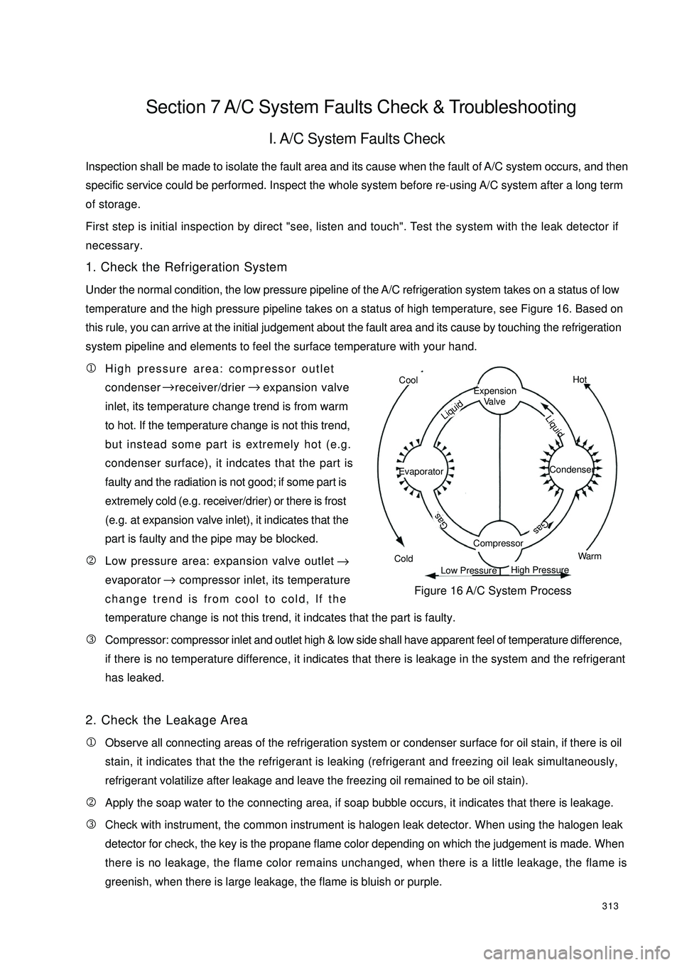
Under the normal condition, the low pressure pipeline of the A/C refrigeration system takes on a status of lowtemperature and the high pressure pipeline takes on a status of high temperature, see Figure 16. Based onthis rule, you can arrive at the initial judgement about the fault area and its cause by touching the refrigeration
system pipeline and elements to feel the surface temperature with your hand.
1High pressure area: compressor outlet
condenser receiver/drier expansion valve
inlet, its temperature change trend is from warm
to hot. If the temperature change is not this trend,
but instead some part is extremely hot (e.g.
condenser surface), it indcates that the part is
faulty and the radiation is not good; if some part is
extremely cold (e.g. receiver/drier) or there is frost
(e.g. at expansion valve inlet), it indicates that the
part is faulty and the pipe may be blocked.
2Low pressure area: expansion valve outlet
evaporator compressor inlet, its temperature
change trend is from cool to cold, If the
temperature change is not this trend, it indcates that the part is faulty.
3Compressor: compressor inlet and outlet high & low side shall have apparent feel of temperature difference,
if there is no temperature difference, it indicates that there is leakage in the system and the refrigerant
has leaked.
2. Check the Leakage Area
1Observe all connecting areas of the refrigeration system or condenser surface for oil stain, if there is oil
stain, it indicates that the the refrigerant is leaking (refrigerant and freezing oil leak simultaneously,
refrigerant volatilize after leakage and leave the freezing oil remained to be oil stain).
2Apply the soap water to the connecting area, if soap bubble occurs, it indicates that there is leakage.
3Check with instrument, the common instrument is halogen leak detector. When using the halogen leak
detector for check, the key is the propane flame color depending on which the judgement is made. When
there is no leakage, the flame color remains unchanged, when there is a little leakage, the flame is
greenish, when there is large leakage, the flame is bluish or purple.CoolColdHotWarmExpension
Va l v eCompressorEvaporator Condenser Gas
GasLiquid LiquidLow PressureHigh PressureFigure 16 A/C System Process → →
→→
Page 323 of 392
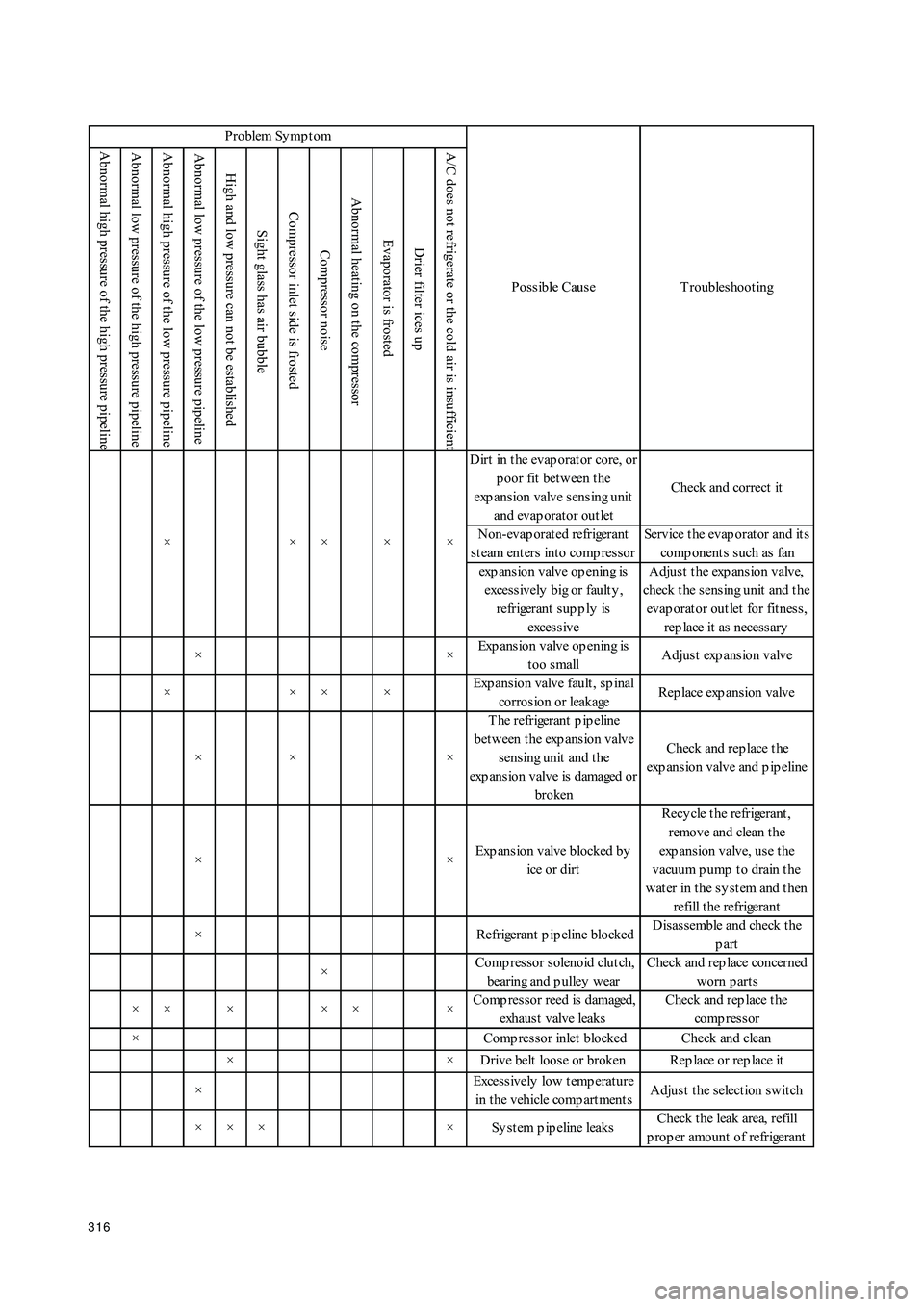
316 Abnormal high pressure of the high pressure pipelineAbnormal low pressure of the high pressure pipeline Abnormal high pressure of the low pressure pipelineAbnormal low pressure of the low pressure pipelineHigh and low pressure can not be establishedSight glass has air bubble Compressor inlet side is frosted Compressor noise Abnormal heating on the compressorEvaporator is frostedDrier filter ices up A/C does not refrigerate or the cold air is insufficientD irt in t he evap orat or core, or
poor fit between the
exp ansion valve sensing unit
and evap orat or out letCheck and correct it
Non-evap orat ed refrigerant
steam enters into compressorService t he evap orat or and it s
comp onent s s uch as fan
exp ans ion valve op ening is
excessively big or faulty ,
refrigerant sup p ly is
exces s iveA djus t t he exp ans ion valve,
check t he s ens ing unit and t he
evap orat or out let for fit nes s ,
rep lace it as necess ary
××Exp ansion valve op ening is
too smallAdjust exp ansion valve
××××Exp ansion valve fault , sp inal
corrosion or leakageRep lace exp ans ion valve
×× ×T he refrigerant p ip eline
bet ween t he exp ansion valve
sensing unit and t he
exp ansion valve is damaged or
brokenCheck and rep lace t he
exp ansion valve and p ip eline
××Exp ansion valve blocked by
ice or dirtRecy cle t he refrigerant ,
remove and clean t he
exp ansion valve, use the
vacuum p ump t o drain t he
water in the system and then
refill t he refrigerant
× Refrigerant p ip eline blockedD is as s emble and check t he
part
× Comp ressor solenoid clutch,
bearing and p ulley w earCheck and rep lace concerned
worn p art s
×××××× Comp ressor reed is damaged,
exhaus t valve leaksCheck and rep lace t he
comp res s or
× Comp res s or inlet blocked Check and clean
× × D rive belt loos e or broken Rep lace or rep lace it
×Exces s ively low t emp erat ure
in t he vehicle comp art ment sAdjust the selection switch
× × × × Sy s t em p ip eline leaksCheck t he leak area, refill
p rop er amount of refrigerant × ×× Problem Symptom
Possible Cause T roubleshoot ing
××
Page 324 of 392
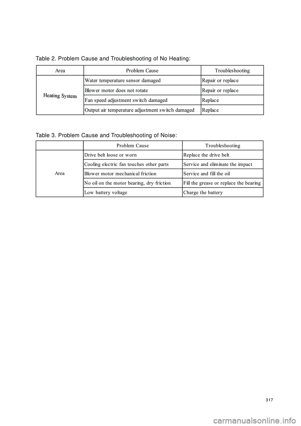
317Table 2. Problem Cause and Troubleshooting of No Heating:Area Problem Cause TroubleshootingH
eat
i
ng
Sy
st
emWater temperature sensor damaged Repair or replac e
Blow er motor does not rotate Repair or replac e
Fan s peed adjus tment sw itc h damaged Replac e
Output air temperature adjustment sw itc h damaged Replac eH
eat
i
ng
Sy
st
emTable 3. Problem Cause and Troubleshooting of Noise:Problem Cause Troubleshooting
Drive belt loose or w orn Replac e the drive belt
Cooling electric fan touc hes other parts Service and eliminate the impac t
Blow er motor mec hanic al fric tion Servic e and fill the oil
N o o il o n t h e m o t o r b e a r in g , d r y f r ic t io n F ill t h e g r e a s e o r r e p la c e t h e b e a r in g
Low battery voltage Charge the battery Ar e a
Page 363 of 392
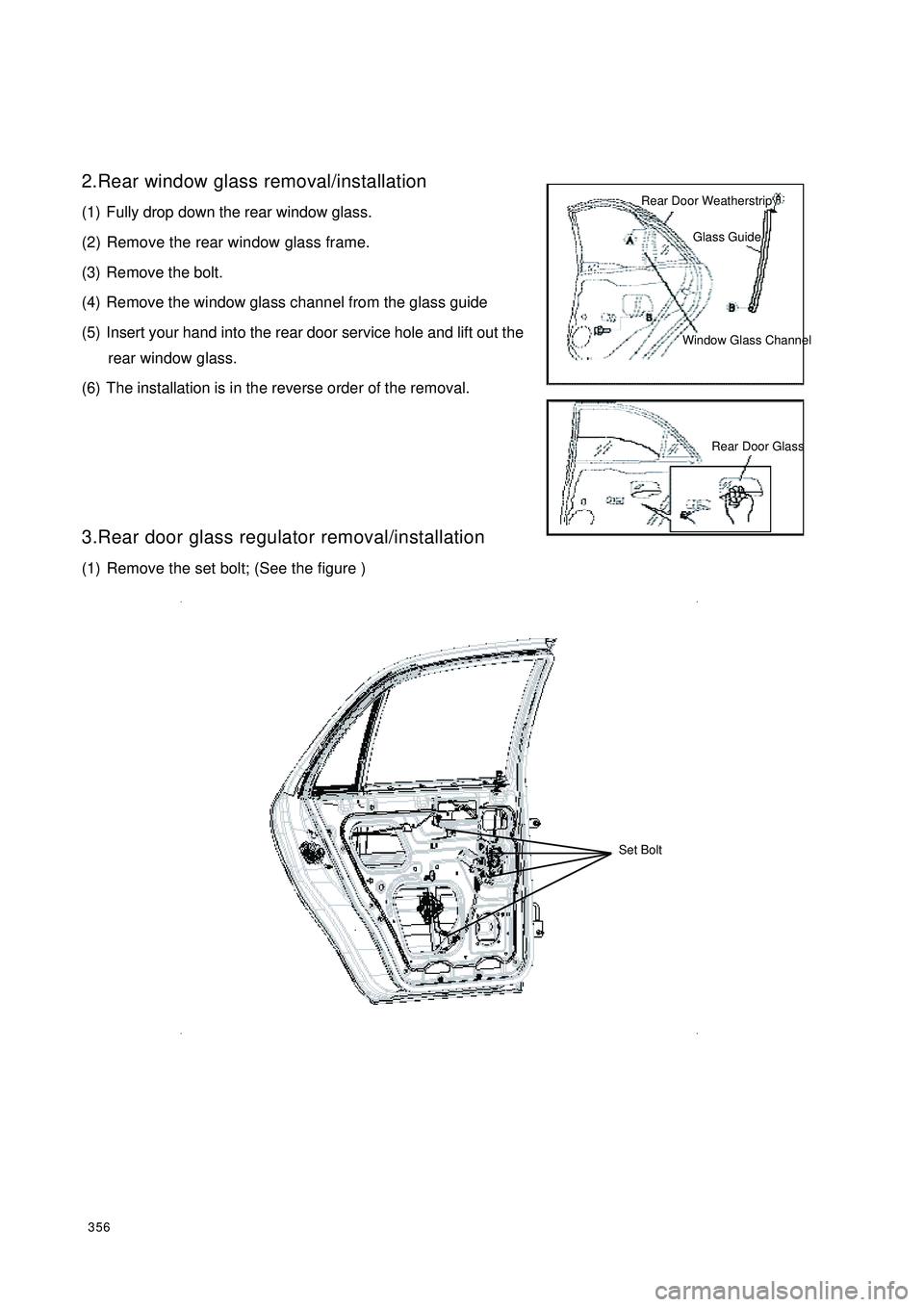
3562.Rear window glass removal/installation
(1) Fully drop down the rear window glass.
(2) Remove the rear window glass frame.
(3) Remove the bolt.
(4) Remove the window glass channel from the glass guide
(5) Insert your hand into the rear door service hole and lift out the
rear window glass.
(6) The installation is in the reverse order of the removal.
3.Rear door glass regulator removal/installation
(1) Remove the set bolt; (See the figure )Rear Door WeatherstripGlass GuideWindow Glass ChannelRear Door Glass Set Bolt
Page 386 of 392
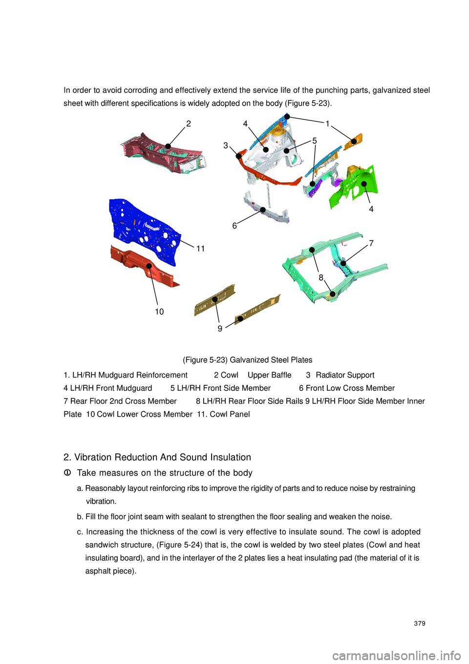
379In order to avoid corroding and effectively extend the service life of the punching parts, galvanized steel
sheet with different specifications is widely adopted on the body (Figure 5-23).
(Figure 5-23) Galvanized Steel Plates
1. LH/RH Mudguard Reinforcement 2 Cowl Upper Baffle 3 Radiator Support
4 LH/RH Front Mudguard 5 LH/RH Front Side Member 6 Front Low Cross Member
7 Rear Floor 2nd Cross Member 8 LH/RH Rear Floor Side Rails 9 LH/RH Floor Side Member Inner
Plate 10 Cowl Lower Cross Member 11. Cowl Panel
2. Vibration Reduction And Sound Insulation
1 11 1
1Take measures on the structure of the body
a. Reasonably layout reinforcing ribs to improve the rigidity of parts and to reduce noise by restraining
vibration.
b. Fill the floor joint seam with sealant to strengthen the floor sealing and weaken the noise.
c. Increasing the thickness of the cowl is very effective to insulate sound. The cowl is adopted
sandwich structure, (Figure 5-24) that is, the cowl is welded by two steel plates (Cowl and heat
insulating board), and in the interlayer of the 2 plates lies a heat insulating pad (the material of it is
asphalt piece).87 5
4 4 21
9 10 63
11
Page 392 of 392
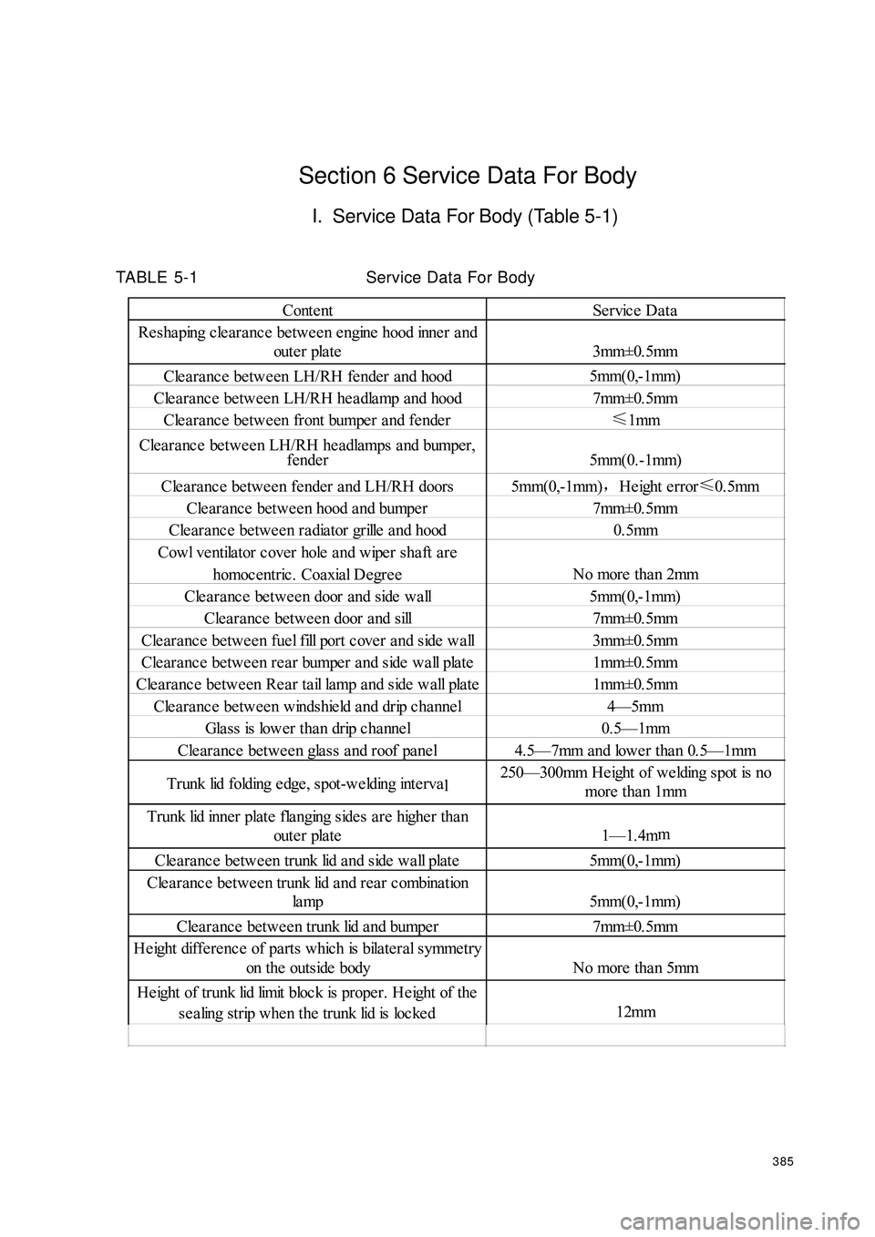
385Section 6 Service Data For BodyI. Service Data For Body (Table 5-1)TABLE 5-1Service Data For BodyContent Service Data
Resha ping cle aranc e be twe e n e ngine hood inne r and
oute r pla te 3mm±0. 5mm
Clea ra nce betwe en LH/RH fender and hood5mm(0,-1mm)
Clea ra nce betwee n LH/RH he adla mp and hood7mm±0.5mmClea ra nce betwe en front bumpe r a nd fe nde r≤
1mmClea ra nc e be twee n LH/RH he adlamps a nd bumper,
fender 5mm(0.-1mm)
Cle a ra nc e be twe e n fender a nd LH/RH doors 5mm(0,-1mm),
Height error≤
0.5mm
Cle ara nce betwe en hood and bumpe r 7mm±0.5mmCle aranc e be twe en ra dia tor grille a nd hood0.5mmCowl ventila tor cover hole a nd wipe r sha ft a re
homoc entric . Coaxial Degre eNo more than 2mmClearance between door and side wall5mm(0,-1mm)
Clea ra nce betwee n door a nd sill 7mm±0.5mm
Cle aranc e be twe en fue l fill port c ove r a nd side wa ll 3mm±0.5mmClearance between rear bumper and side wall plate 1mm±0.5mmClearance between Rear tail lamp and side wall plate 1mm±0.5mmClea ra nce betwee n windshie ld a nd drip c ha nnel4—5mmGlass is lower than drip channel0.5—1mmCle ara nce betwe en gla ss a nd roof pa nel 4.5—7mm and lower tha n 0.5—1mmTrunk lid folding e dge , spot-we lding inte rval250—300mm He ight of we lding spot is no
more tha n 1mmTrunk lid inner plate fla nging sides a re highe r than
oute r pla te 1—1. 4mmCle ara nce betwe en trunk lid a nd side wa ll plate 5mm(0,-1mm)
Clearance between trunk lid and rear combination
la mp 5mm(0,-1mm)
Clea ra nce betwee n trunk lid a nd bumper 7mm±0.5mmHe ight diffe re nce of pa rts which is bila teral symme try
on the outside bodyNo more than 5mmHeight of trunk lid limit bloc k is proper. He ight of the
se a ling strip when the trunk lid is loc ked12mm