service GEELY CK 2008 User Guide
[x] Cancel search | Manufacturer: GEELY, Model Year: 2008, Model line: CK, Model: GEELY CK 2008Pages: 392, PDF Size: 38.86 MB
Page 79 of 392

724. Big fuel consumption
(1) Symptom:
Engine power is ok, but the fuel consumption is big, exhaust pipe discharges black smoke.
(2) Causes and Troubleshooting:
a. When idling, idle speed is high and shall be adjusted;
b. Water temperature sensor fault, service or replace it;
c. Water temperature switch and thermostat fault, repair or replace it;
d. Oxygen sensor fault, repair or replace it;
e. Fuel pressure is big and shall be adjusted;
f. Injector fault (fuel leakage), repair or replace it;
g. Throttle position sensor fault, repair or replace it;
h. Fuel pressure regulator is damaged and shall be replaced;
i. Intake pressure temperature sensor fault, repair or replace it.
5. Unstable idle, liable to be turned off
(1) Symptom:
Engine starts normally, but the idle is unstable regardless of cold or hot status, idle speed is too low and
the engine is liable to be turned off.
(2) Causes and Troubleshooting
a. Poor idle control valve operation, repair or replace it;
b. Low idle speed and faulty or improperly adjusted idle control valve, troubleshoot it;
c. Water temperature sensor fault, repair or replace it;
d. Poor intake system seal, need to be repaired;
e. High voltage spark is too weak, spark plug carbon deposit or electrode clearance is too small, need
to be repaired, cleared and adjusted;
f. Pressure sensor fault, repair or replace it;
g. The compression pressure in the cylinder is too low, need to be serviced;
h. Fuel line pressure is too low, needed to be serviced;
i. Air cleaner is clogged, clean or replace it;
j. Poor injector atomization, fuel leakage, block or big injection variation, need to be repaired;
(3) Diagnosis procedure (Figure 152)
6. Unstable idle at cold status, liable to be turned off
(1) Symptom
During the cold start, idle is unstable and engine is liable to be turned off, the normal idle is recovered
after warming of the engine.
(2) Causes and Troubleshooting
a. Water temperature sensor fault, repair or replace it;
b. idle control valve fault, repair or replace it.
Page 106 of 392

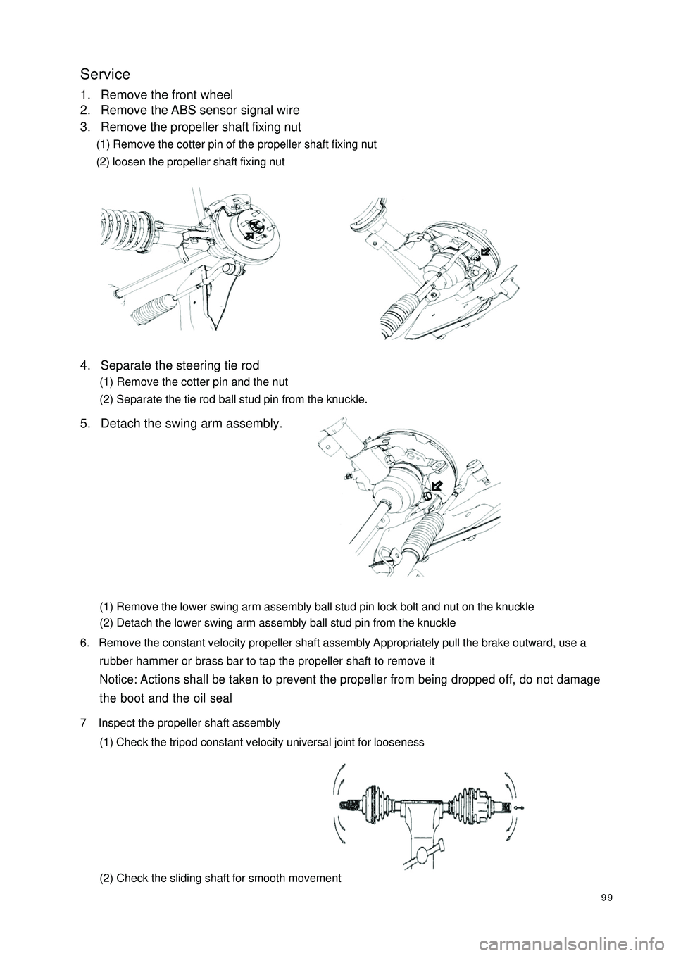
99Service1. Remove the front wheel
2. Remove the ABS sensor signal wire
3. Remove the propeller shaft fixing nut
(1) Remove the cotter pin of the propeller shaft fixing nut
(2) loosen the propeller shaft fixing nut
4. Separate the steering tie rod
(1) Remove the cotter pin and the nut
(2) Separate the tie rod ball stud pin from the knuckle.
5. Detach the swing arm assembly.
(1) Remove the lower swing arm assembly ball stud pin lock bolt and nut on the knuckle
(2) Detach the lower swing arm assembly ball stud pin from the knuckle
6. Remove the constant velocity propeller shaft assembly Appropriately pull the brake outward, use a
rubber hammer or brass bar to tap the propeller shaft to remove itNotice: Actions shall be taken to prevent the propeller from being dropped off, do not damage
the boot and the oil seal7 Inspect the propeller shaft assembly
(1) Check the tripod constant velocity universal joint for looseness
(2) Check the sliding shaft for smooth movement
Page 133 of 392

126Chapter 7 WheelSection 1 Tire InspectionInspection1. Check the tires for appearance and proper inflation pressure.
Check for inflation pressure after the vehicle stops for over 15min.
2. Using a dial gauge, check the runout of tire.
The tire runout should be no more than 3.0mm
Notice
(1) You must use specified tire and special wheel rim provided by the authorized service
center, otherwise it may affect the normal safe running of the vehicle and even result in
accidents!
(2) If the wheel rim is damaged, you must go to the authorized service center for service and
replacement! Never use the wheel rim of any other model!
3. Changing tire position
It is recommended to change the tire for each 10000km driving. See the figure for where to change each
tire
4. Inspect wheel dynamic balance
The imbalance should be no more than 8.0g. Otherwise, there will be extra vibration and noise when
driving.Tire module Tire inflationpressure
(Kpa
)
175/65 R14 82H 220Front
Page 135 of 392

128Chapter 8 Power Steering SystemSection 1 Power Steering SystemPower Steering System DescriptionPower Steering System consists of the steering wheel, steering transmit device, power steering fixed device
and steering pipelines. The steering gear is rack and pinion type.
Major parameters for steering system:
Cautions:
1. Cautions for steering system
Make sure of the correct replacement of parts, incorrect replacement might affect the performance of
the steering system and lead to driving accidents.
2. Cautions for SRS System
This vehicle is equipped with SRS (Supplemental Restraint System), driver side air bag and front passenger
side air bag.
Failure to carry out service operations in the correct sequence could cause the unexpected deployment of
the air bag during servicing, possibly leading to a serious accident.Parameter
3.26
Inner 37.6°
Outer 33.3°
≤
10.5m Item
Steering Wheel total revolutions
Ma ximum Front
Wheel Turn Angle
Minimum Turning Dia me ter
Page 140 of 392

13311. Complete the service or replace the steering column assembly, the installation procedure is in the reverseorder of the removal
Notice:
(1) after the installation of the ignition lock core, check the steering lock operation: the
steering mechanism lock when the ignition key is pulled out; the steering mechanism
unlock when the key is inserted and turned to ACC position
(2)The torque of the 2 bolts and 2 nuts securing the steer column assembly:
16~26N.m
(3) connect the wire harness into place and make sure the wiring is good
(4) After properly adjust the positions of the combination switch and the steering column
upper and lower cover, tighten the 3 screws attaching the combination switch and the
steering column
(5) Torque of the universal joint yoke and steering gear assembly locking bolt: 22~34N.m
(6) Torque of the 4 set bolts of the dust cover and press plate: 16~26N.m
(7) When installing the steering wheel assembly, align the matchmarks of the steering wheel
and steering main shaft assembly,
Torque of the steering wheel specific inner torx bolt: 40~60N.m
(7) Check the air bag, it is not allowed to use the air bag parts from another vehicle
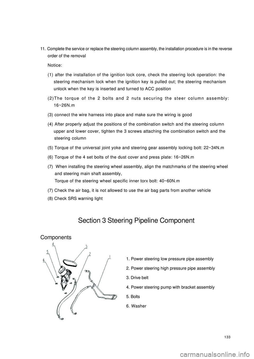
(8) Check SRS warning lightSection 3 Steering Pipeline ComponentComponents1. Power steering low pressure pipe assembly
2. Power steering high pressure pipe assembly
3. Drive belt
4. Power steering pump with bracket assembly
5. Bolts
6. Washer
Page 205 of 392

198Chapter 5 Light SystemSection 1 Survey of Light SystemI. COMPOSITION1. Front combination lamp assembly: turn signal lamp, high beam, low beam, head lamp, front position lamp.
2. Rear combination lamp: turn signal lamp, back-up lamp, rear fog lamp, tail lamp, brake lamp, retro reflector.
3. Front fog lamp
4. Side turn signal lamp
5. High mounted stop lamp
6. Rear trunk lamp
7. License plate lamp
8. Interior dome lamp
9. Rear row reading lamp
10. Door lampshield and bulb assemblyII. NOTES FOR REPAIR1. NOTES WHEN REPAIRING ELECTRICAL EQUIPMENTS
(a) Disconnect the battery ground cable.
2. Notes when replacing a headlamp bulb
(a) Before replacing a halogen bulb, turn the headlamp OFF to make it cool.
(b) When installing a new halogen bulb, do not touch the glass part of the bulb with bare hands.
(c) If there is oil stain on the surface of halogen bulb (headlamp and front fog lamp) when the lamps are
turned ON, its service life will be shortened.
(d) Halogen bulbs (headlamp and front fog lamp) have pressurized gas inside and require special handling.
They can explode if dropped to ground.The glass fragments will splash up.
(e) When replacing, make sure to use the bulbs with the same power, same model.
(f) After the bulb is installed, make the lamp holder tight.
Page 245 of 392

238Section 4 Audio and Video System ReplacementI. Notice on operationPlease explain to the customer that the AM/FM broadcast channel information will be cleared when remov-
ing the battery negative terminal cable. Record the channel information before removing the negative termi-
nal cable if necessary. Reset after connecting the negative terminal cable.
�yAll cassette tapes and CDs must be taken out before radio removal and installation.
�yIf the cassette tapes and CDs can not be taken out due to radio fault. Do not take them out by force.
Drive the vehicle to Service Station.
�yMake sure the grounding bolts are tightened before antenna removal and installation.
�yThere will be noise when receiving electric wave if the grounding bolts are not tightened.
�yDon't touch the speaker cone.Intermediate Multiple CD main unit Radio assemblyInstrument PanelMultiple DVD main unit
Page 250 of 392

2435. Servicing operation shall be carried out 60s after the negative
(-) terminal cable is disconnected from the battery. In addition,
the disconnected negative (-) terminal cable shall be protected
with insulating tape for insulation.
In order to deploy an airbag within a certain time period after the
battery is disconnected, condenser in the ECU shall retain some
electrical energy. Otherwise, it could lead to a serious accident
because of the unexpected deployment of airbag.
6. During spray paint work, ECU, airbag assembly, clock spring
assembly, etc shall be removed and kept in place to avoid the effects of overheat. (Over 93¡æ)
7. When the SRS is serviced, a diagnostic scan meter is used to clear the DTC to enable the normal work of
the warning light.1 1 D AB Lo D r iv er a ir b ag , lo w p o s it io n
13 (Option) PAB Hi Passenger airbag, high position
14 (Option) PAB Lo Passenger airbag, low position
20Passenger Airbag Deactivation
Indic atorPassenger airbag deac tivation indic ator light
27PPD/ Passenger Airbag
Deac tivation Sw itch, HighPassenger airbag deac tivation sw itc h, high position
30 Crash Output Crash outputInsulating TapeBatteryCableDriver Side
Warning LampPassenger Side
Warning LampDriver Seat Inflation
Element & AirbagCrash Sensor &
Diagnostic ModuleFront/RH Inflation
Element & Airbag
Page 251 of 392

244II. TEST INSTRUMENTS
III. TROUBLESHOOTING1. Basic process of trouble diagnosis
�yDTC of the present fault may coexist with that of the history fault.
NOTICE:
�yAfter the new SRS ECU is installed, the warning light of the SRS, with the ignition switch ON, will be on
for 6s and then go out permanently, indicating SRS works normal. In this case, no service is needed.
Otherwise, system diagnosis and service shall be carried out.
�y If with the ignition switch ON, the warning light of the SRS is not on, the relevant circuits of the warning
light shall be serviced. Then go on with the operation and enable it to work.
2. Check SRS warning light
(1) Turn the ignition switch ON and find out whether the warning light is on.
(2) Six seconds after the process of ON-OFF, confirm that the warning light goes out permanently.
(3) Otherwise, diagnosis and checking have to be involved in.
3. System Diagnosis
The SRS ECU (HAE2.5) will perform a series of circular diagnostic tests to check the readiness of the SRS
functions. This test can avoid unexpected explosion of the restrain system and in the same time ensure the
necessary explosion in a crash. If a trouble is detected, the SRS ECU (HAE2.5) will store a proper DTC and
turn on the warning light indicating a trouble for service.Instrument Designation Usage
Check system troubles of the SRS, and
clear the DTC of ECU Diagnostic detector
(Hi-DS T Scan meter)
Spec ia l dia gnostic mete rWL Remains
ONUse scan meter and K line to
connect with Scan Meter ECULocate a
Trouble Trouble-
shootingClear
DTC
Page 257 of 392

250(2) Trouble indication
1In case of a trouble, the warning light will indicate. If the external trouble is a history trouble, the indication
will be cancelled. When the history trouble happens for no less than 5 times, the indicator light will remain
on even if there is no more trouble. "Low battery voltage" shall not be counted in the total number of
troubles.
2Only a service worker can reset a displayed or history trouble. The internal troubles of a SRS ECU
(HAE2.5) or the "crash record" of a trouble cannot be reset, in which case the SRS ECU (HAE2.5) shall
be replaced.
(3) Microcontroller-independent warning light on
Microcontroller with definitive troubles cannot fulfill its functions, thus cannot control the warning light. In
this case, the warning light will light up through proper circuit regardless of the microcontroller as stated
below:
�yMalfunction of the battery supplying power to SRS ECU (HAE2.5): the warning lights are turned
on continuously by means of the drive function of the selfcheck light.
�yLoss of internal working voltage: the warning light remains on.
�yReset due to trigger failure of the watchdog: the warning light blinks.
�yMicrocontroller out of work: the warning light always lights up.
�yIncomplete insertion of SRS ECU (HAE2.5) connector: the warning light remains on by means of
a shorting bar.
The diagnostic procedures can well be illustrated as follows:
If it is found that the SRS warning light remains on, follow the undermentioned procedures to check even if
the light goes out eventually. First, a scan meter is used to check the location of the trouble.
Then£¬go on with the checking in accordance with specific methods and procedures for the correspondent
location.
a. If the result indicates that it is an internal trouble or that the SRS is already detonated, replace the
ECU directly.
b. Troubleshooting.