diagram GEELY FC 2008 Workshop Manual
[x] Cancel search | Manufacturer: GEELY, Model Year: 2008, Model line: FC, Model: GEELY FC 2008Pages: 419, PDF Size: 13.87 MB
Page 11 of 419
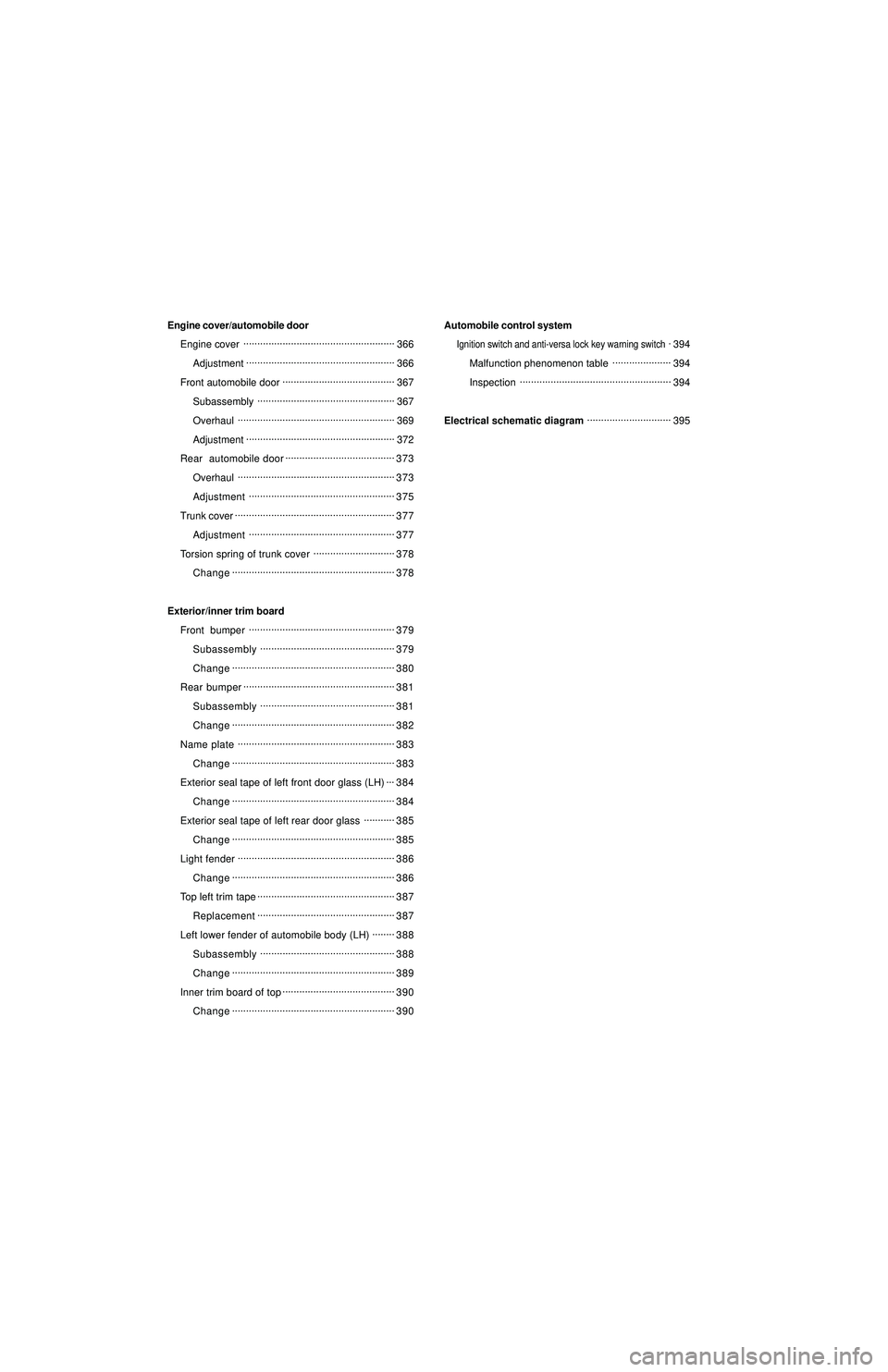
Engine cover/automobile door
Engine cover......................................................
366
Adjustment.....................................................
366
Front automobile door........................................
367
Subassembly.................................................
367
Overhaul........................................................
369
Adjustment.....................................................
372
Rear automobile door.......................................
373
Overhaul........................................................
373
Adjustment....................................................
375
Trunk cover.........................................................
377
Adjustment....................................................
377
Torsion spring of trunk cover.............................
378
Change..........................................................
378
Exterior/inner trim board
Front bumper....................................................
379
Subassembly................................................
379
Change..........................................................
380
Rear bumper......................................................
381
Subassembly................................................
381
Change..........................................................
382
Name plate........................................................
383
Change..........................................................
383
Exterior seal tape of left front door glass (LH)...
384
Change..........................................................
384
Exterior seal tape of left rear door glass...........
385
Change..........................................................
385
Light fender........................................................
386
Change..........................................................
386
Top left trim tape.................................................
387
Replacement.................................................
387
Left lower fender of automobile body (LH)........
388
Subassembly................................................
388
Change..........................................................
389
Inner trim board of top........................................
390
Change..........................................................
390Automobile control system
Ignition switch and anti-versa lock key warning switch.394
Malfunction phenomenon table.....................
394
Inspection......................................................
394
Electrical schematic diagram..............................
395
Page 22 of 419
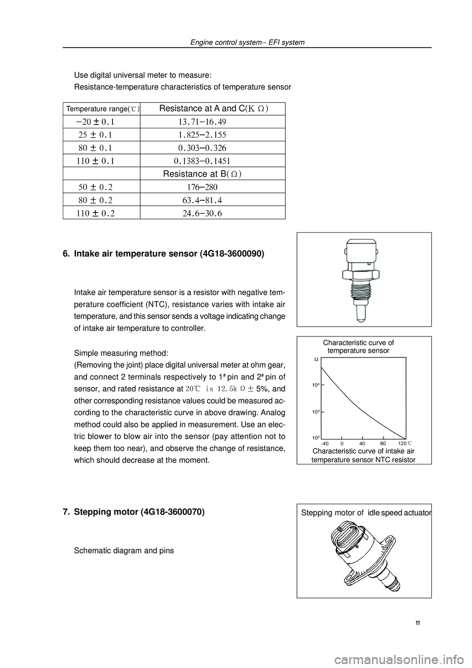
Characteristic curve of intake air
temperature sensor NTC resistorCharacteristic curve of
temperature sensorStepping motor ofidle speed actuator6. Intake air temperature sensor (4G18-3600090)Intake air temperature sensor is a resistor with negative tem-
perature coefficient (NTC), resistance varies with intake air
temperature, and this sensor sends a voltage indicating change
of intake air temperature to controller.
Simple measuring method:
(Removing the joint) place digital universal meter at ohm gear,
and connect 2 terminals respectively to 1# pin and 2# pin of
sensor, and rated resistance at 5%, and
other corresponding resistance values could be measured ac-
cording to the characteristic curve in above drawing. Analog
method could also be applied in measurement. Use an elec-
tric blower to blow air into the sensor (pay attention not to
keep them too near), and observe the change of resistance,
which should decrease at the moment.7. Stepping motor (4G18-3600070)Schematic diagram and pinsEngine control system·- EFI systemUse digital universal meter to measure:
Resistance-temperature characteristics of temperature sensor 11 Temperature range( Resistance at A and CResistance at B
Page 23 of 419
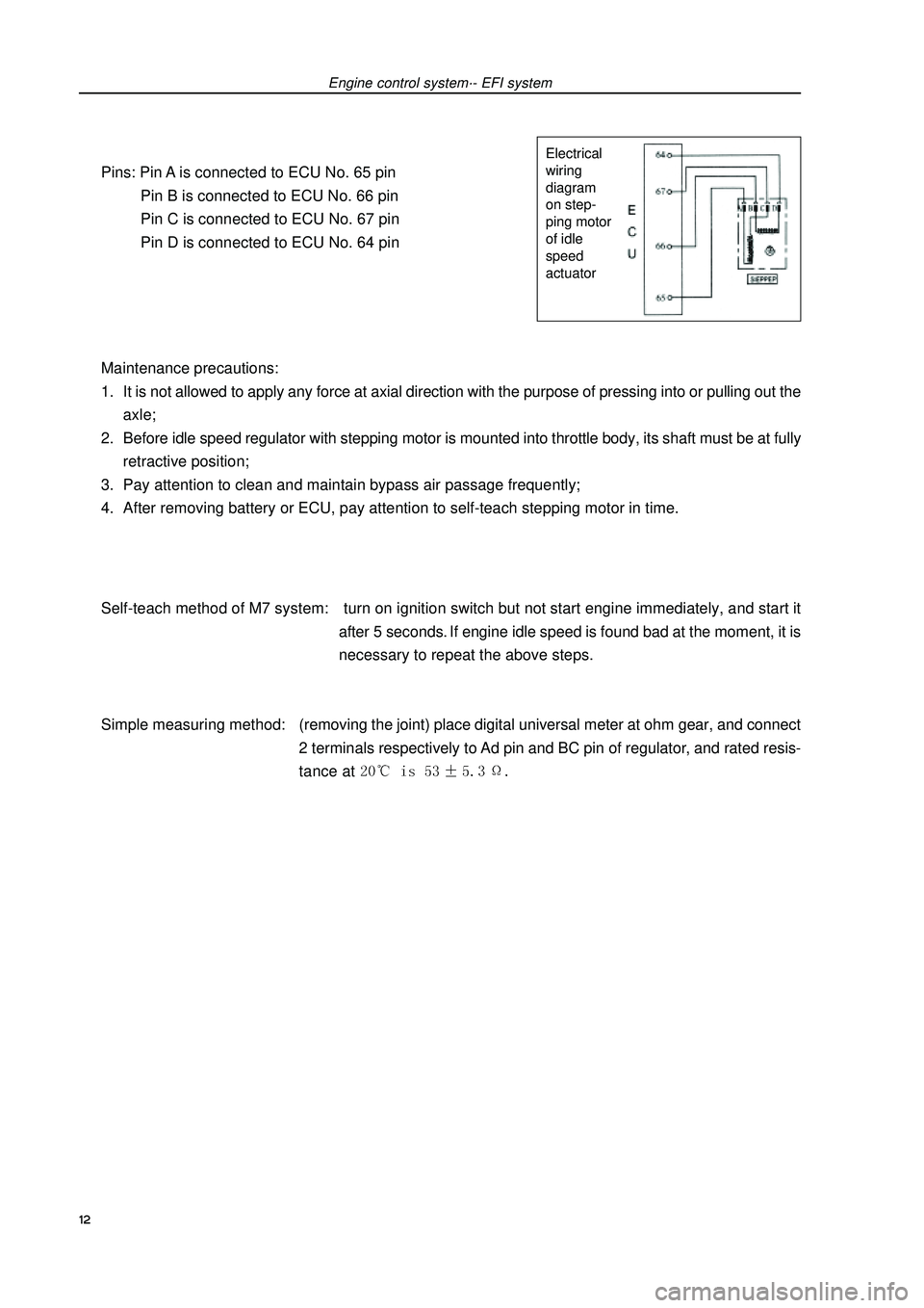
Pins: Pin A is connected to ECU No. 65 pin
Pin B is connected to ECU No. 66 pin
Pin C is connected to ECU No. 67 pin
Pin D is connected to ECU No. 64 pin
Maintenance precautions:
1. It is not allowed to apply any force at axial direction with the purpose of pressing into or pulling out the
axle;
2. Before idle speed regulator with stepping motor is mounted into throttle body, its shaft must be at fully
retractive position;
3. Pay attention to clean and maintain bypass air passage frequently;
4. After removing battery or ECU, pay attention to self-teach stepping motor in time.
Self-teach method of M7 system: turn on ignition switch but not start engine immediately, and start it
after 5 seconds. If engine idle speed is found bad at the moment, it is
necessary to repeat the above steps.
Simple measuring method:(removing the joint) place digital universal meter at ohm gear, and connect
2 terminals respectively to Ad pin and BC pin of regulator, and rated resis-
tance at Engine control system·- EFI systemElectrical
wiring
diagram
on step-
ping motor
of idle
speed
actuator12
Page 26 of 419
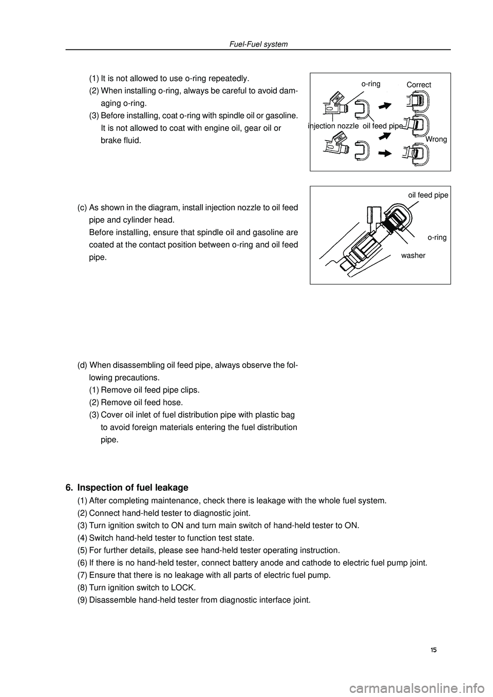
Fuel-Fuel system(1) It is not allowed to use o-ring repeatedly.
(2) When installing o-ring, always be careful to avoid dam-
aging o-ring.
(3) Before installing, coat o-ring with spindle oil or gasoline.
It is not allowed to coat with engine oil, gear oil or
brake fluid.
(c) As shown in the diagram, install injection nozzle to oil feed
pipe and cylinder head.
Before installing, ensure that spindle oil and gasoline are
coated at the contact position between o-ring and oil feed
pipe.
(d) When disassembling oil feed pipe, always observe the fol-
lowing precautions.
(1) Remove oil feed pipe clips.
(2) Remove oil feed hose.
(3) Cover oil inlet of fuel distribution pipe with plastic bag
to avoid foreign materials entering the fuel distribution
pipe.injection nozzle6. Inspection of fuel leakage(1) After completing maintenance, check there is leakage with the whole fuel system.
(2) Connect hand-held tester to diagnostic joint.
(3) Turn ignition switch to ON and turn main switch of hand-held tester to ON.
(4) Switch hand-held tester to function test state.
(5) For further details, please see hand-held tester operating instruction.
(6) If there is no hand-held tester, connect battery anode and cathode to electric fuel pump joint.
(7) Ensure that there is no leakage with all parts of electric fuel pump.
(8) Turn ignition switch to LOCK.
(9) Disassemble hand-held tester from diagnostic interface joint.15o-ringoil feed pipeoil feed pipeo-ringwasherCorrect
Wrong
Page 27 of 419
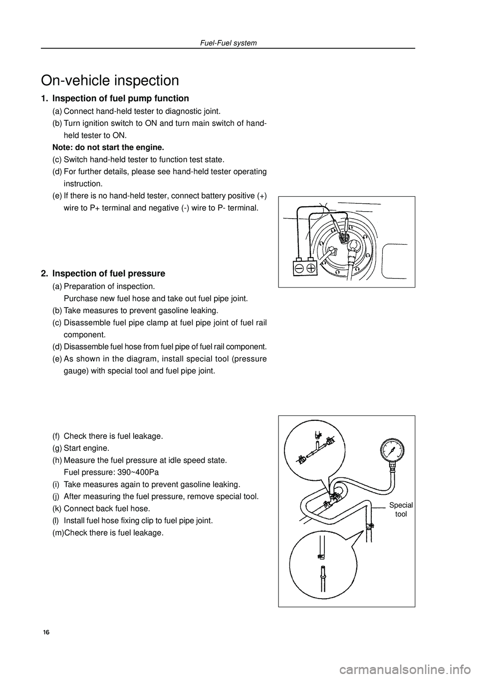
On-vehicle inspection1. Inspection of fuel pump function(a) Connect hand-held tester to diagnostic joint.
(b) Turn ignition switch to ON and turn main switch of hand-
held tester to ON.
Note: do not start the engine.
(c) Switch hand-held tester to function test state.
(d) For further details, please see hand-held tester operating
instruction.
(e) If there is no hand-held tester, connect battery positive (+)
wire to P+ terminal and negative (-) wire to P- terminal.2. Inspection of fuel pressure(a) Preparation of inspection.
Purchase new fuel hose and take out fuel pipe joint.
(b) Take measures to prevent gasoline leaking.
(c) Disassemble fuel pipe clamp at fuel pipe joint of fuel rail
component.
(d) Disassemble fuel hose from fuel pipe of fuel rail component.
(e) As shown in the diagram, install special tool (pressure
gauge) with special tool and fuel pipe joint.
(f) Check there is fuel leakage.
(g) Start engine.
(h) Measure the fuel pressure at idle speed state.
Fuel pressure: 390~400Pa
(i) Take measures again to prevent gasoline leaking.
(j) After measuring the fuel pressure, remove special tool.
(k) Connect back fuel hose.
(l) Install fuel hose fixing clip to fuel pipe joint.
(m)Check there is fuel leakage.Fuel-Fuel systemSpecial
tool 16
Page 32 of 419
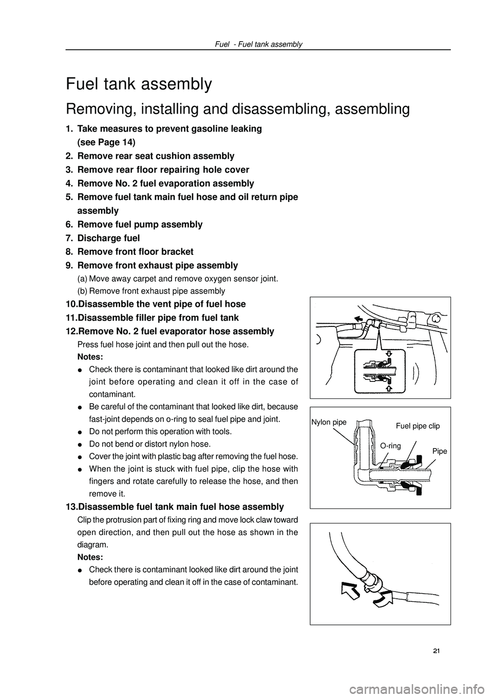
Fuel - Fuel tank assemblyFuel tank assembly1. Take measures to prevent gasoline leaking
(see Page 14)
2. Remove rear seat cushion assembly
3. Remove rear floor repairing hole cover
4. Remove No. 2 fuel evaporation assembly
5. Remove fuel tank main fuel hose and oil return pipe
assembly
6. Remove fuel pump assembly
7. Discharge fuel
8. Remove front floor bracket
9. Remove front exhaust pipe assembly(a) Move away carpet and remove oxygen sensor joint.
(b) Remove front exhaust pipe assembly10.Disassemble the vent pipe of fuel hose
11.Disassemble filler pipe from fuel tank
12.Remove No. 2 fuel evaporator hose assemblyPress fuel hose joint and then pull out the hose.
Notes:Check there is contaminant that looked like dirt around the
joint before operating and clean it off in the case of
contaminant.Be careful of the contaminant that looked like dirt, because
fast-joint depends on o-ring to seal fuel pipe and joint.Do not perform this operation with tools.Do not bend or distort nylon hose.Cover the joint with plastic bag after removing the fuel hose.When the joint is stuck with fuel pipe, clip the hose with
fingers and rotate carefully to release the hose, and then
remove it.13.Disassemble fuel tank main fuel hose assemblyClip the protrusion part of fixing ring and move lock claw toward
open direction, and then pull out the hose as shown in the
diagram.
Notes:Check there is contaminant looked like dirt around the joint
before operating and clean it off in the case of contaminant. 21 Removing, installing and disassembling, assemblingFuel pipe clipNylon pipeO-ring
Pipe
Page 33 of 419
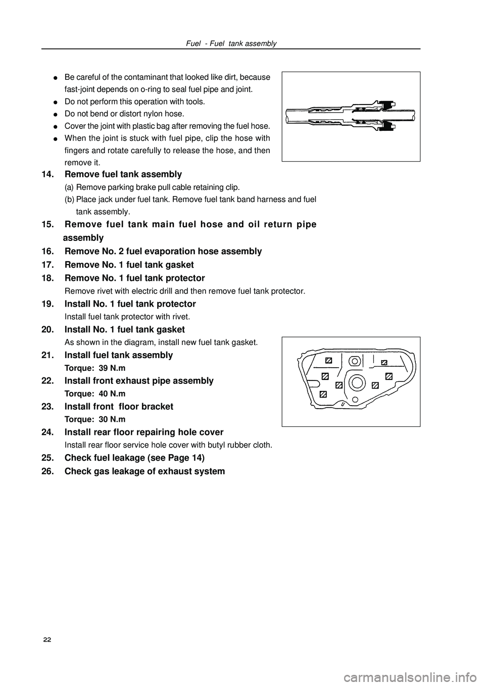
Fuel - Fuel tank assemblyBe careful of the contaminant that looked like dirt, because
fast-joint depends on o-ring to seal fuel pipe and joint.Do not perform this operation with tools.Do not bend or distort nylon hose.Cover the joint with plastic bag after removing the fuel hose.When the joint is stuck with fuel pipe, clip the hose with
fingers and rotate carefully to release the hose, and then
remove it.14. Remove fuel tank assembly(a) Remove parking brake pull cable retaining clip.
(b) Place jack under fuel tank. Remove fuel tank band harness and fuel
tank assembly.15. Remove fuel tank main fuel hose and oil return pipe
assembly
16. Remove No. 2 fuel evaporation hose assembly
17. Remove No. 1 fuel tank gasket
18. Remove No. 1 fuel tank protectorRemove rivet with electric drill and then remove fuel tank protector.19. Install No. 1 fuel tank protectorInstall fuel tank protector with rivet.20. Install No. 1 fuel tank gasketAs shown in the diagram, install new fuel tank gasket.21. Install fuel tank assemblyTorque: 39 N.m22. Install front exhaust pipe assemblyTorque: 40 N.m23. Install front floor bracketTorque: 30 N.m24. Install rear floor repairing hole coverInstall rear floor service hole cover with butyl rubber cloth.25. Check fuel leakage (see Page 14)
26. Check gas leakage of exhaust system
22
Page 41 of 419
![GEELY FC 2008 Workshop Manual Engine mechanism - Valve clearanceValve clearanceAdjustment1. Remove engine plastic hood components.
2. Remove ignition coil components [4G18-3705110].
3. Remove cylinder head cover components [4G18-
GEELY FC 2008 Workshop Manual Engine mechanism - Valve clearanceValve clearanceAdjustment1. Remove engine plastic hood components.
2. Remove ignition coil components [4G18-3705110].
3. Remove cylinder head cover components [4G18-](/img/58/57161/w960_57161-40.png)
Engine mechanism - Valve clearanceValve clearanceAdjustment1. Remove engine plastic hood components.
2. Remove ignition coil components [4G18-3705110].
3. Remove cylinder head cover components [4G18-
1003130].
4. Remove engine right bottom shield.
5. Turn crankshaft to cylinder 1 compression top dead
center position.(a) Turn crankshaft pulley to align its groove with “o” mark on
timing chain hood.
(b) Check dot marks on camshaft timing sprocket and VVT
timing sprocket, and they should be in a line on timing chain
hood surface as shown in the diagram.
Hint: if not, turn crankshaft for one circle again
and align the above marks.6. Check valve clearance.(a) Only check the valves shown in the diagram.
(1) Measure the clearance between valve tappet and cam-
shaft with plug gauge.
(2) Record valve clearance measuring value exceeding
specification, and this value will be used to determine
valve tappet thickness that needs change.
Valve clearance (cold vehicle)Intake airExhaust(b) Turn crankshaft for one circle ), and cylinder 4 is
turned to compression top dead center position.
(c) Only check the valves shown in the diagram. Measure valve
clearance (see step (a)).7. Remove drive beltSlowly turn drive belt tensioner clockwise to loosen it.
Then remove drive belt and put back drive belt tensioner slowly
and gently. 30 Mark
Mark
Mark
Timing chain
hood surface
Groove
Page 42 of 419
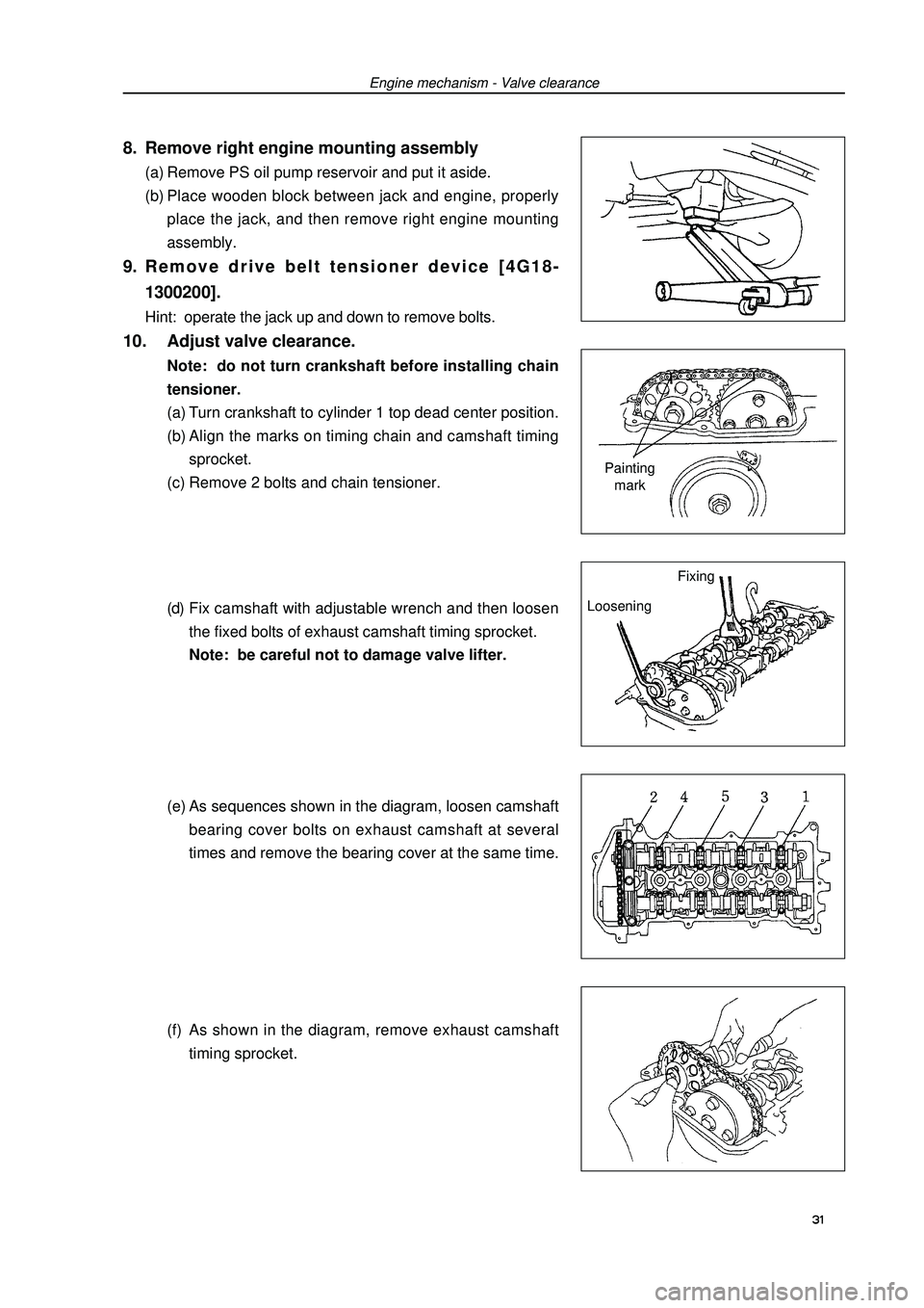
Engine mechanism - Valve clearance8. Remove right engine mounting assembly(a) Remove PS oil pump reservoir and put it aside.
(b) Place wooden block between jack and engine, properly
place the jack, and then remove right engine mounting
assembly.9. Remove drive belt tensioner device [4G18-
1300200].Hint: operate the jack up and down to remove bolts.10. Adjust valve clearance.Note: do not turn crankshaft before installing chain
tensioner.
(a) Turn crankshaft to cylinder 1 top dead center position.
(b) Align the marks on timing chain and camshaft timing
sprocket.
(c) Remove 2 bolts and chain tensioner.
(d) Fix camshaft with adjustable wrench and then loosen
the fixed bolts of exhaust camshaft timing sprocket.
Note: be careful not to damage valve lifter.
(e) As sequences shown in the diagram, loosen camshaft
bearing cover bolts on exhaust camshaft at several
times and remove the bearing cover at the same time.
(f) As shown in the diagram, remove exhaust camshaft
timing sprocket.Painting
mark
LooseningFixing 31
Page 43 of 419
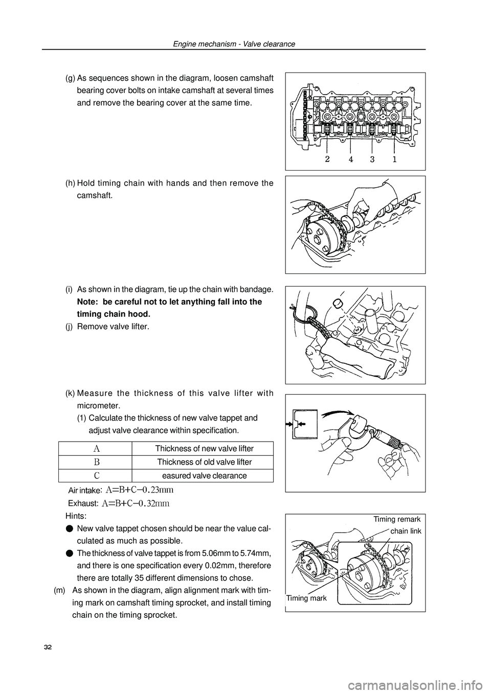
Engine mechanism - Valve clearanceThickness of new valve lifterThickness of old valve liftereasured valve clearance(g) As sequences shown in the diagram, loosen camshaft
bearing cover bolts on intake camshaft at several times
and remove the bearing cover at the same time.
(h) Hold timing chain with hands and then remove the
camshaft.
(i) As shown in the diagram, tie up the chain with bandage.
Note: be careful not to let anything fall into the
timing chain hood.
(j) Remove valve lifter.
(k) Measure the thickness of this valve lifter with
micrometer.
(1) Calculate the thickness of new valve tappet and
adjust valve clearance within specification.: Exhaust: Hints:New valve tappet chosen should be near the value cal-
culated as much as possible.The thickness of valve tappet is from 5.06mm to 5.74mm,
and there is one specification every 0.02mm, therefore
there are totally 35 different dimensions to chose.
(m) As shown in the diagram, align alignment mark with tim-
ing mark on camshaft timing sprocket, and install timing
chain on the timing sprocket. 32Timing remarkchain linkTiming mark