steering wheel adjustment GEELY FC 2008 Workshop Manual
[x] Cancel search | Manufacturer: GEELY, Model Year: 2008, Model line: FC, Model: GEELY FC 2008Pages: 419, PDF Size: 13.87 MB
Page 8 of 419

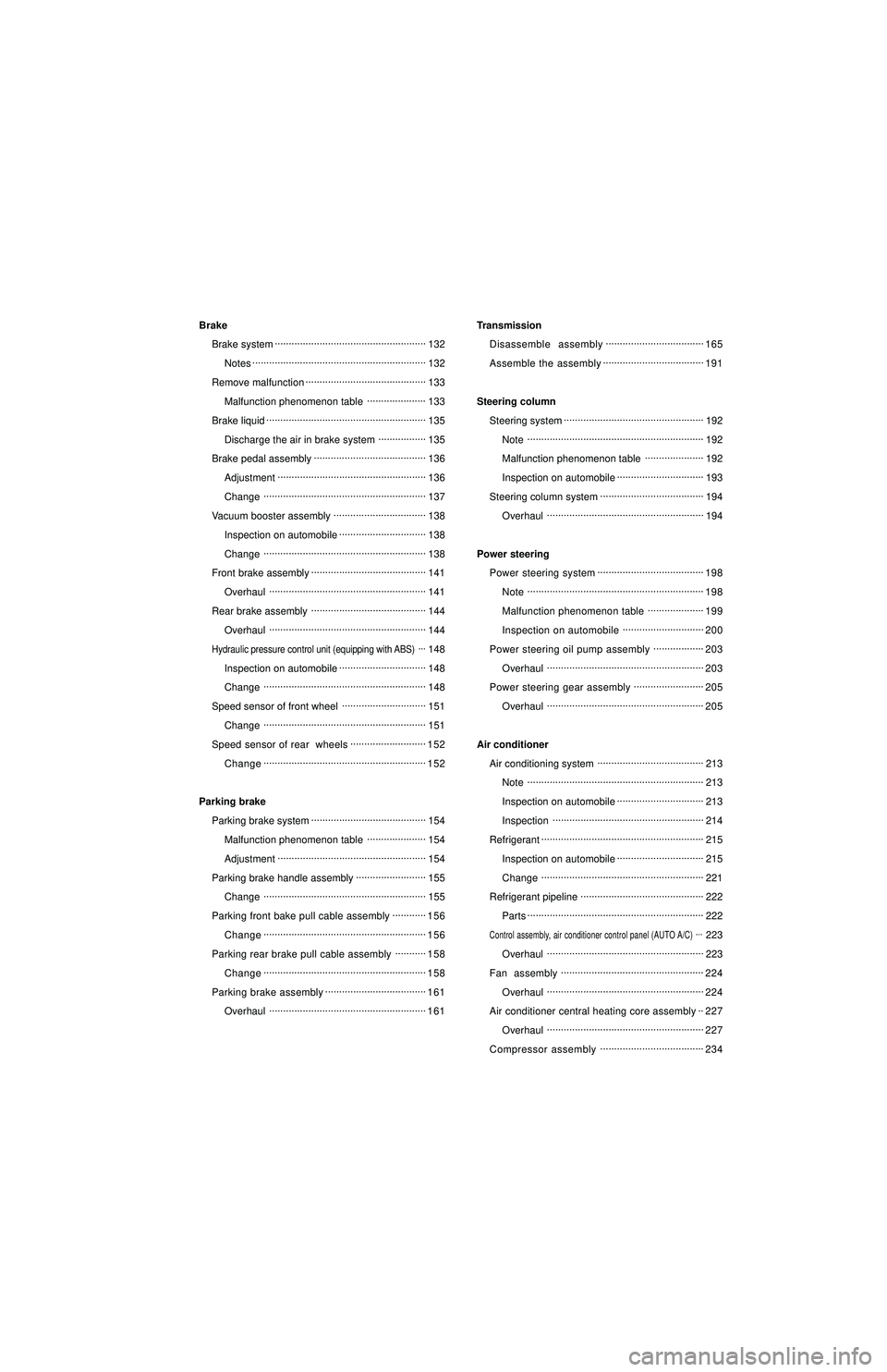
Brake
Brake system......................................................
132
Notes..............................................................
132
Remove malfunction...........................................
133
Malfunction phenomenon table.....................
133
Brake liquid.........................................................
135
Discharge the air in brake system.................
135
Brake pedal assembly........................................
136
Adjustment.....................................................
136
Change..........................................................
137
Vacuum booster assembly.................................
138
Inspection on automobile...............................
138
Change..........................................................
138
Front brake assembly.........................................
141
Overhaul........................................................
141
Rear brake assembly.........................................
144
Overhaul........................................................
144Hydraulic pressure control unit (equipping with ABS)...148
Inspection on automobile...............................
148
Change..........................................................
148
Speed sensor of front wheel..............................
151
Change..........................................................
151
Speed sensor of rear wheels...........................
152
Change..........................................................
152
Parking brake
Parking brake system.........................................
154
Malfunction phenomenon table.....................
154
Adjustment.....................................................
154
Parking brake handle assembly.........................
155
Change..........................................................
155
Parking front bake pull cable assembly............
156
Change..........................................................
156
Parking rear brake pull cable assembly...........
158
Change..........................................................
158
Parking brake assembly....................................
161
Overhaul........................................................
161Transmission
Disassemble assembly...................................
165
Assemble the assembly....................................
191
Steering column
Steering system..................................................
192
Note...............................................................
192
Malfunction phenomenon table.....................
192
Inspection on automobile...............................
193
Steering column system.....................................
194
Overhaul........................................................
194
Power steering
Power steering system......................................
198
Note...............................................................
198
Malfunction phenomenon table....................
199
Inspection on automobile.............................
200
Power steering oil pump assembly..................
203
Overhaul........................................................
203
Power steering gear assembly.........................
205
Overhaul........................................................
205
Air conditioner
Air conditioning system......................................
213
Note...............................................................
213
Inspection on automobile...............................
213
Inspection......................................................
214
Refrigerant..........................................................
215
Inspection on automobile...............................
215
Change..........................................................
221
Refrigerant pipeline............................................
222
Parts...............................................................
222Control assembly, air conditioner control panel (AUTO A/C)...223
Overhaul........................................................
223
Fan assembly...................................................
224
Overhaul........................................................
224
Air conditioner central heating core assembly..
227
Overhaul........................................................
227
Compressor assembly.....................................
234
Page 97 of 419

Front suspension - front suspension systemFront suspensionFront suspension systemTable on trouble occurrenceThis table could help you find out failure causes, and each figure in the table indicates the possible
sequence of failure causes, please check every part as the sequence, and replace if necessary.Trouble occurrence Possible trouble part Pages to refer to
1. Tire (abrasion or improper tire pressure) 109
2. Wheel alignment (incorrect) 87
Deflection/single side 3. Steering linkage (looseness or abrasion) -
4. Shaft hub bearing (abrasion) 123
5. Suspension parts (abrasion) -
6. Steering gear (poor adjustment or breakage) -
1. Vehicle (overload) -
Bottoming 2. Spring (elastic fatigue) 90
3. Absorber (abrasion) 90
1. Tire (abrasion or improper tire pressure) 109
Swaying left and right/ 2. Stabilizer bar (bending or breakage) 96shaking forward and backward3. Absorber (abrasion) 90
1. Tire (abrasion or improper tire pressure) 109
2. Wheel (poor balance) 109
3. Absorber (abrasion) 90
Front wheel shimmy 4. Wheel alignment (incorrect) 87
5. Ball joint (abrasion) 99
6. Shaft hub bearing (looseness or abrasion) 123
7. Steering linkage (looseness or abrasion) -
8. Steering gear (poor adjustment or breakage) -
1. Tire (abrasion or improper tire pressure) 109
Abnormal tire abrasion 2. Wheel alignment (incorrect) 87
3. Absorber(abrasion) 90
4. Suspension parts (abrasion) -86
Page 98 of 419

Front suspension - Front wheel alignmentFrontRearIf toe-in is not within specification, please adjust left and
right levers of steering gear.4. Adjustment of toe-in(a) Remove dust cover fixing clip.FrontRearToe-in(Total)Front wheel alignmentAdjustment1. Inspection(a) Check tire is worn and inflation pressure is proper.
Tire inflation pressure under normal temperature:Tire size Front and rear kPa*1 It is used under the condition of speed below 160 km/h.
*2 It is used under the condition of speed above 160 km/h.
(b) Check tire run-out with dial indicator.
Tire run-out: 3.0mm.2. Measurement of vehicle heightVehicle height:
(General road)
(Coarse road)
Measuring point:
A. Height for ground and front wheel center
B. Height for ground and bolt center in front of lower
control arm
C. Height for ground and fixed bolt center of rear axle beam
D. Height for ground and rear wheel center
Note: adjust vehicle height to standard value before checking front wheel alignment.
If vehicle height does not conform to regulations, please shake upward and downward or lift vehicle
body to adjust vehicle height.3. Inspection of toe-inToe-in:Front87
Page 100 of 419

Front suspension - Front wheel alignment7. Adjustment of camberNote: after adjusting the camber, please check toe-in.
(a) Remove front wheels.
(b) Remove 2 nuts under absorber.
If it is necessary to repeat using bolts or nuts, please coat
oil to thread of nuts.
(c) Clean nut absorber and attachment face of steering knucle.
(d) Temporarily install 2 nuts.
(e) Push or pull lower end of absorber in the direction that cam-
ber requires adjustment to adjust the camber.
(f) Tighten nut.
Torque: 15310 N.m
(g) Install front wheels.
Torque: 10310 N.m
(h) Check camber.89