service GEELY MK 2008 Workshop Manual
[x] Cancel search | Manufacturer: GEELY, Model Year: 2008, Model line: MK, Model: GEELY MK 2008Pages: 416, PDF Size: 25.19 MB
Page 3 of 416
Geely “MK” series sedans (JL7132U,JL7132HU,JL7152U,JL7152HU,JL7162U) are brand
new superior models developed by Geely Group who has fully proprietary intellectual property
rights. As a result of the three years of involvements and efforts of the experts from Geely Automo-
bile Research Institute, these sedans reach international leading level in model design, power,
sense of comfort, safety and manufacturing technology while featured in beautiful appearance,
economy, environment protection and safety. The meaning of MK implied that Geely Automobile
has a great development from caterpillar to butterfly. With respect to the power, Geely “MK” series
sedans are equipped with 1.3L, 1.5L, and 1.6L EFI engines developed and manufactured by Geely
itself, and has reached “Chinese III” (Euro III) emission standard.
This manual contains a detailed description of the structures and principles, servicing and adjustment,
removal, assembling technology and matching clearance of the parts of the Geely “MK” sedans
with torque information of the bolts and nuts as well as schematic diagram for special tool operation.
This manual also introduces the transmission control system of the automatic transmission models,
vehicle electric circuits and elaborates ABS system, SRS, BOSCH M7.9.7 electronic control fuel
injection and ignition system, rear parking radar, sound, air conditioning and onboard hands-free
phone system. You can refer to this manual for the information about the regular maintenance,
servicing, adjustment, troubleshooting, removal and installation procedure, specific operations of
the “MK” sedans.
This manual covers the matching relation among the engine assembly, transmission assembly and
the vehicle, but does not have the further description of the structures and principles of the engine
and transmission assemblies and their servicing process. You can refer to the service manuals
solely prepared for engine assembly and transmission assembly for these information.
All information in this manual is based on the latest products released at the time of publication of
this manual. However, the specifications and procedures may need to be modified, and the subse-
quent change will be revealed in later versions.
This manual is prepared by Geely Automobile Research Institute under the assistance of technical
staff from Zhejiang Geely Automobile Co., Ltd and Geely International Corporation. Readers
discovering during the use of this manual the errors and careless omissions due to limited skills of
the preparers and tight schedule are encouraged and pled to contact Geely International in time for
our timely correction of the mistakes.ForewordGeely International Corporation
Nov . 2007
Page 9 of 416
Chapter 14 Outside Rearview Mirror................................................................................. 6-37
Chapter 15 Door Protecting Stripe.................................................................................... 6-38
Chapter 16 Carpet and Insulator....................................................................................... 6-39
Chapter 17 Moonroof Assembly (Optional)...................................................................... 6-40
Chapter 18 Plug List........................................................................................................... 6-42Part 7 BodyChapter 1 Survey................................................................................................................ 7-1
Section 1 Body Structure ................................................................................................ 7-1
Chapter 2 Body Repair....................................................................................................... 7-9
Section 1 Body Damage Forms and Requirements for Repair ...................................... 7-9
Section 2 Typical Technique of Body Panel Repair ....................................................... 7-16
Section 3 Repair After Body Damage ............................................................................ 7-16
Section 4 Features and Composition of Automobile Body ............................................ 7-24
Section 5 Painting Techniques After Body Repair ......................................................... 7-35
Section 6 Service Data For for Body .............................................................................. 7-36Attachment: Body Key Dimensions
Appendix: Torque Table of the Fasteners for Important AssemblyTable of Contents VI
Page 10 of 416
General Information - How to Use This Manual1-1Part 1 General InformationChapter 1 How to Use This ManualI. Instruction1. General Information
(1)This manual conform to the first part of GB/T1.1--2000 Standardization Guide: The structure and prepar-
ing rule of the standard.
(2)Generally, the repairing job can be divided into the following 3 procedures:
1. Diagnosis
2. Removal and installation, replacement, disassembly and inspection, adjustment
3. Final inspection
(3) The first procedure “Diagnosis” (the details refers to each section or chapter) and second procedure “Re-
moval and installation, replacement, disassembly and inspection, adjustment” are scattered in the chapters and
sections, and this manual omits the third procedure “Final inspection”.
(4) This manual does not include the following basic operations which are imperative in real scenarios.
operate the jack or lifter
b. clean the removed parts if necessary.
c. inspect the appearance
2. Preparation
SST (Special Service Tools) and SSM (Special Service Materials) may be required and correctly used based
on the repairing condition, make sure the job procedure is followed.
3. Repair Procedure
(1) The disassembly illustration is placed under the title.
(2) The illustration shows the disassembly of the parts to help you understand the assembly of the parts. (3) Non-reusable parts need to be coated with grease, and the precoated parts and torque are specially shownin the disassembly illustration.
(4) Sometimes, the illustrations of the similar model are used where there may be some details differently
from the actual vehicle.
(5)The operational procedure is described in the following ways:
a. The illustration shows what to do and where to do it.
b. The task heading tells what to do.
c.The detailed text tells how to perform the task and gives other information such as specifications and
warnings.
4. Specification
Specifications are presented in bold type throughout the manual.
5.Term Definition
6. International System of Unit
The Units given in this manual are primarily expressed according to the International System of Unit.Caution indicates there is a possibility of injury to you or other people.
Notice indicates the possibility of damage to the components being repaired.
Tip provides additional information to help you perform the repair efficiently.a.
Page 15 of 416
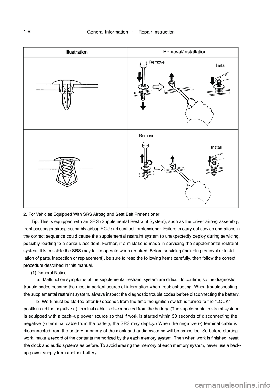
General Information - Repair Instruction1-6IllustrationRemoval/installation2. For Vehicles Equipped With SRS Airbag and Seat Belt Pretensioner
Tip: This is equipped with an SRS (Supplemental Restraint System), such as the driver airbag assembly,
front passenger airbag assembly airbag ECU and seat belt pretensioner. Failure to carry out service operations in
the correct sequence could cause the supplemental restraint system to unexpectedly deploy during servicing,
possibly leading to a serious accident. Further, if a mistake is made in servicing the supplemental restraint
system, it is possible the SRS may fail to operate when required. Before servicing (including removal or instal-
lation of parts, inspection or replacement), be sure to read the following items carefully, then follow the correct
procedure described in this manual.
(1) General NoticeInstall Remove
Install Remove a. Malfunction symptoms of the supplemental restraint system are difficult to confirm, so the diagnostic
trouble codes become the most important source of information when troubleshooting. When troubleshooting
the supplemental restraint system, always inspect the diagnostic trouble codes before disconnecting the battery.
b. Work must be started after 90 seconds from the time the ignition switch is turned to the "LOCK"
position and the negative (-) terminal cable is disconnected from the battery. (The supplemental restraint system
is equipped with a back--up power source so that if work is started within 90 seconds of disconnecting the
negative (-) terminal cable from the battery, the SRS may deploy.) When the negative (-) terminal cable is
disconnected from the battery, memory of the clock and audio systems will be cancelled. So before starting
work, make a record of the contents memorized by the each memory system. Then when work is finished, reset
the clock and audio systems as before. To avoid erasing the memory of each memory system, never use a back-
up power supply from another battery.
Page 33 of 416
2-12Section 2 Maintenance Category and Content of MK SedanAs the vehicle is being used, its technical performance changes as the mileage accumulates and being affected by
various factors, which results in decrease of power, fuel economy, safety, and increase of emission pollutions,
noise and incidents. So timely maintenance during vehicle usage eliminates potential risks and prevents incidents
from happening, improves vehicle integrity and technical functionality, and prolongs useful life of the vehicle.
According to the vehicle technical requirements and usage history, maintenance of freedom Cruiser sedan can be
classified into several categories.I. first time maintenanceFirst time maintenance is also called breaking-in maintenance. It is performed when the vehicle mileage has
accumulated to 1500~2500km in breaking-in period. First time maintenance must be conducted at the appointed
service shops. It includes:
1. Check if there is any leak in engine, transmission, and differential. Fix if there is any.
2. Replace engine oil filter, engine oil and ATF for A/T.
3. Check the level of engine coolant, braking fluid, windshield washing fluid, power steering fluid and if there
is any leak. Refill if the level is too low and repair if there is any leak.
4. Check if there is any damage in triangle arm and ball joint, connection ball joint, triangle arm flexible hinge,
or the ball joint is loose. If there is, fix or replace it.
5. Check if the drive shaft dust cover is damaged. If there is, replace it.
6. Check if there is any leak in steering mechanism, or front and rear absorber and fix it there is any.
7. Check the tire pressure, front 230kpa, and rear 210kpa.II. Regular maintenanceAfter first time maintenance, the vehicle is in regular usage life. During regular use, the vehicle needs to be
maintained regularly according to the way it is used in.
1.Regular maintenance for vehicles used under extreme bad conditions. Any of the condition below is defined
as extreme bad condition:
(1) Frequent start.
(2) Often drive the vehicle in dusty circumstances.
(3) Drive the vehicle in hot areas (such as in summer in the south).
(4) Often drive in cold areas (often runs short trips, engine temperate cannot reach regular work temperature).
Vehicles ran under extreme bad conditions need to be maintained every 5000km.
2. Regular maintenance for vehicles Vehicles that have not been through extreme bad conditions need to be
maintained every 7500km.
Regular maintenance is required to be performed at Geely service shop, too.
List of parts that need to be replaced regularly is in table 1.
Maintenance timetable is in table2.III. Geely maintenance programGeely recommends following Geely maintenance program.
The intervals of maintenance schedules are determined by mileage meter or time periods. Maintain the vehicle
when either meets the schedule. For details, please refer to the schedule.Usage and Maintenance of MK Series - Maintenance Category and Content of MK Sedan
Page 39 of 416

2-18Section 3 Daily Maintenance of MK SedanDaily maintenance means operation of vehicle regular inspection, cleaning, fastening, and refilling according to
vehicle usage and condition on the basis of regular maintenance to make sure the vehicle is at good status. Daily
maintenance can be performed by driver or professional automotive mechanics in daily use of vehicle. But some
of the items must be conducted by professional mechanics at service shops.
1. Maintenance of air cleaner
Air cleaner filters the air that is coming into engine for the first time. Dust and other dirt filtered out gathers in the
induction tube. Air cleaner filters a lot of dust and dirty, so it must be cleaned in time.
2. Maintenance of air filter
Air filter does not only filter the dust and dirt in the air, but also keeps smooth ventilation. Its status has great effects
on the fuel economy and power of the engine, so it must be checked and maintained in time.
Before it is time to replace air filter, maintain it. Remove the filter, knock it with hand or stick to get rid of dust
on the filter and remove dirt inside the filter cover according to the cleanness of the road that the vehicle usually
runs on.
ATTENTION: do not clean the filter with wet cloth. Fasten the filter well when installing it back.
3. Maintenance of battery
Battery is used to start the vehicle and supply power to electrical facilities. Its status directly affects the regular
usage of the vehicle, especially for vehicles equipped with electrical controlled facilities. Keeping the battery in
good technical status and connections is especially important. It is necessary to often perform the following
inspections and maintenance in regular usage:
(1) Clean the outside of battery Inspect if the battery case or cover surface is dirty or has dirt, oil, or other dirty
things regularly. Clean it and keep the surface dry to avoid electrical leak caused by cover deformation.
(2) Check battery connections Bad connection between battery electrode and cable results in low engine start
speed which makes it difficult to start the vehicle or the vehicle cannot be started because of low output voltage
from battery. Loose connection at battery end leads to damage of electrical components and loss of trouble code
and other information stored in RAM of the computer system as a result of low voltage. Therefore, it is necessary
to check if the connection of cables on the battery electrode is good. When it is found loose, it must be fastened.
If there is any rust, the cables must be loosened, washed clean and be connected again.
4. Maintenance of tires and wheels
(1) Keeping tires and wheels under good condition is very important to vehicle fuel consumption and driving
safety. Therefore, inspect and maintain the tires regularly. Every 10000 km, the wheels should be adjusted. Follow
the sequence in picture 3:
Judge if there is any hidden problems in vehicle chassis mechanism by observing wear in different places, andfinding out the hidden problems does not only help you to understand
the technical status of the vehicle, but also benefits driving safety.
a. Serious wear on both edges of tire tread, means tires often
work with low tire pressure.
b. Wear of middle of the tire tread is mainly because the tires
are used with high tire pressure.This kind of wear shortens
the useful life of tires, and may result in sudden flat tire
when the vehicle runs on uneven road surface or meets any
obstacles.Usage and Maintenance of MK Series - Daily Maintenance of MK Sedan
Page 44 of 416
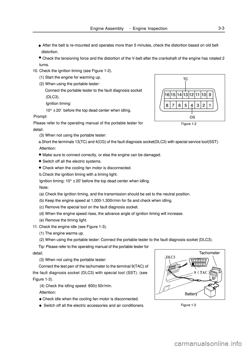
Figure 1-2
Figure 1-3Engine AssemblyEngine Inspection3-3 After the belt is re-mounted and operates more than 5 minutes, check the distortion based on old belt
distortion.
Check the tensioning force and the distortion of the V-belt after the crankshaft of the engine has rotated 2
turns.
10. Check the ignition timing (see Figure 1-2).
(1) Start the engine for warming up.
(2) When using the portable tester:
Connect the portable tester to the fault diagnosis socket
(DLC3).
Ignition timing:
before the top dead center when idling.
Prompt:
Please refer to the operating manual of the portable tester for
detail.
(3) When not using the portable tester:
a.Short the terminals 13(TC) and 4(CG) of the fault diagnosis socket(DLC3) with special service tool(SST).
Attention:
Make sure to connect correctly, or else the engine can be damaged.
Switch off all the electric systems.
Check when the cooling fan motor is disconnected.
b.Check the ignition timing with a timing light.
Ignition timing: 10°±20' before the top dead center when idling.
Note:
(a) Check the ignition timing, and the transmission should be set to the neutral position.
(b) Keep the engine speed at 1,000-1,300r/min for 5s and check when idling.
(c) Remove the special tool on the fault diagnosis socket.
(d) When the engine speed rises, the advance angle of ignition timing will increase.
(e) Remove the timing light.
11. Check the engine idle (see Figure 1-3).
(1) The engine warms up.
(2) When using the portable tester: Connect the portable tester to the fault diagnosis socket (DLC3).
Tip: Please refer to the operating manual of the portable tester for
detail.
(3) When not using the portable tester:
Connect the test pen of the tachometer to the terminal 9(TAC) of
the fault diagnosis socket (DLC3) with special tool (SST). (see
Figure 1-3).
(4) Check the idling speed: 800±50r/min.
Attention:
Check idle when the cooling fan motor is disconnected.
Switch off all the electric accessories and air conditioners.Tachometer
Battery10°±20' -
Page 100 of 416

15. Install LF steering knuckle assembly
Notice:
The hub bearing could be damaged if it is subjected to the vehicle
weight, such as when moving the vehicle with the drive shaft
bearing removed.
Therefore if it is absolutely necessary to place the vehicle weight
on the hub bearing, first support it with the special service tool for
front hub bearing.
16. Check left constant velocity drive shaft assembly
(1) Check the outboard joint for apparent looseness.
(2) Check that the inboard joint slide smoothly.
(3) Check the inboard joint for radial looseness.
(4) Check the boot for damage.
Notice:
Place the drive shaft assembly on level surface during the
inspection.
17. Remove inboard joint big clamp
Using a screw driver, loosen the inboard joint big clamp.
18. Remove inboard joint small clamp
Using a screw driver, loosen the inboard joint small clamp.
19. Separate inboard joint boot
Separate the outboard joint boot from the outboard Rzeppa joint
assembly.
20. Remove left tripod joint assembly
(1) Wipe off the old grease from the tripod joint assembly.
(2) Place the matchmarks between the tripod joint assembly and
the outboard Rzeppa joint.
Notice:
Do not punch the matchmarks.Propeller Shaft/DriveshaftFront Driveshaft4-23Mark -
Page 144 of 416

Chapter 8 Power Steering SystemSection 1 Power Steering System3. Precaution: (1) Precaution for steering system
Make sure of the correct replacement of parts, incorrect replacement might affect the performance of the
steering system and lead to driving accidents.
(2) Precaution for SRS System
This vehicle is equipped with SRS (Supplemental Restraint System), driver side air bag and front passenger
side air bag.
Failure to carry out service operations in the correct sequence could cause the unexpected deployment of
the air bag during servicing, possibly leading to a serious accident.1. Power Steering System Description Power Steering System consists of the steering wheel, steering transmit device, power steering fixed device
and steering pipelines. The steering gear is rack and pinion type.2. Major parameters for steering system:Power Steering System-Power Steering System4-67Item
Steering Wheel total revolutions
Maximum Front
Wheel Turn Angle
Minimum Turning DiameterParameter
3.58±0.1
37.2°±2°/ 32°±2°
37.2°±2°/ 32°±2°
10.4
mInner
OuterSuspected Area
1. Tire (improperly inflated)
2. Power steering fluid (insufficient)
3. Front wheel alignment (incorrect)
4. Steering knuckle (worn)
5. Swing arm ball stud pin joint (worn)
6. Steering column (bent or binding)
7. Power steering pump assembly
8. Power steering gear assembly
1. Tire (improperly inflated)
2. Front wheel alignment (incorrect)
3. Steering column (bent or binding)
4. Power steering gear assemblySymptom
Heavy steering
Poor return4. Symptom Table The table below is helpful to find the cause of the problem. The numbers indicate the priority of the likely cause
of the problem. Check each part in order. Repair or replace these parts or assemblies if necessary.
Page 205 of 416
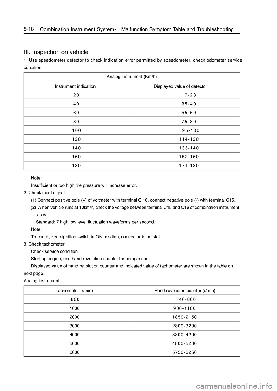
Analog instrument (Km/h)
Instrument indication Displayed value of detector
20 17-23
40 35-40
60 55-60
80 75-80
100 95-100
120 114-120
140 133-140
160 152-160
180 171-180
Tachometer (r/min) Hand revolution counter (r/min)
800 740-860
1000900-1100
20001850-2150
30002800-3200
40003800-4200
50004800-5200
60005750-6250 Note:
Insufficient or too high tire pressure will increase error.
2. Check input signal
(1) Connect positive pole (+) of voltmeter with terminal C 16, connect negative pole (-) with terminal C15.
(2) When vehicle runs at 10km/h, check the voltage between terminal C15 and C16 of combination instrument
assy.
Standard: 7 high low level fluctuation waveforms per second.
Note:
To check, keep ignition switch in ON position, connector in on state
3. Check tachometer
Check service condition
Start up engine, use hand revolution counter for comparison.
Displayed value of hand revolution counter and indicated value of tachometer are shown in the table on
next page.
Analog instrumentIII. Inspection on vehicle1. Use speedometer detector to check indication error permitted by speedometer, check odometer service
condition.5-18Combination Instrument System -Malfunction Symptom Table and Troubleshooting