Light GEELY MK 2008 User Guide
[x] Cancel search | Manufacturer: GEELY, Model Year: 2008, Model line: MK, Model: GEELY MK 2008Pages: 416, PDF Size: 25.19 MB
Page 31 of 416
2-10 must be running at medium speed without load. Increase the speed and load gradually with the
accumulation of breaking-in mileage.
b. Because the brake plat is not broken in on a new vehicle,in order to ensure safety and reduce wear,avoid
harsh brake, and brake for multiple times to break in the brake plate faster.
c. It is better to avoid driving vehicle on steep roads or in bad conditions during breaking-in period.
d. Pay special attention to engine coolant temperature meter and oil pressure meter.Check engine oil level
frequently and make sure engine works in normal temperature and good lubrication.
e. Maintain the vehicle strictly according to first-time maintenance requirements to bring the vehicle into
normal usage life under good condition.
7.vehicle towing
There are towing facilities both in the front and rear end of MK-1 sedan for towing other vehicles and being towed.
To ensure safety, pay attention to the following instructions when towing.
(1) Towing car Towing car should be started and shifted steadily.The speed should be no more than 40km/h.
(2) Follow the instructions below when being towed:
a. Steering system of the vehicle being towed works well.
b. Braking system of the vehicle being towed works well or it cannot be towed with a rope and must be
towed with the towing shaft instead.
c. Release park brake and shift the transmission to neutral gear when the vehicle is being towed.
d. Turn the ignition switch to ACC to allow turning signal lights,braking indicator to be turned on when
necessary.
e. The towing rope must be tensioned in the towing process.
f. If the purpose of towing is to start the engine, shift the transmission to the 2nd or 3rd gear to increase
engine speed. It is good for starting the engine.
8. Instructions to save fuel when using the vehicle
(1) Reasonable load Do not store useless articles in luggage compartment because they consumes fuel for
nothing.
(2) Correct driving style Instructions as follows:
a. When engine is started, do not heat it but press the accelerator pedal slightly, drive the vehicle slowly
and accelerate gradually.
b. Shift to higher gears when driving to allow the engine to work at appropriate engine speed and avoid
running the engine at low or high speed. The engine speed should be higher than 2500r/min when
driving, and higher than 3000r/min when up-shifting.
c. Keep the vehicle speed stable, and avoid harsh acceleration and frequent braking.
d. Pay attention to vehicle speed. Drive at high speed results in excessive fuel consumption.
(3) Organize vehicle usage well Pay attention to the following two instructions.
a. Organize vehicle usage time and avoid short trips. Because at the beginning when the vehicle is started
(around 1km), the engine has not reached its efficiency point, and the fuel consumption doubles
compared to regular.
b. Select a good driving route, avoid driving through the city or blocks with heavy traffic.
(4) Keep the vehicle under good work condition Strictly follow instructions to maintain the vehicle to make
sure the vehicle is under good technical working condition, and inspect and replace key parts that affect vehicle
fuel consumptions. For example:Usage and Maintenance of MK Series - Usage of MK Series
Page 37 of 416
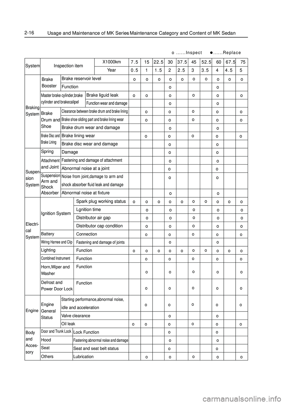
2-16......Inspect ......Replace7.5 15 22.5 30 37.5 45 52.5 60 67.5 75
0.5 1 1.5 2 2.5 3 3.5 4 4.5 5System Inspection itemX1000km
YearBraking
SystemBrake reservoir level
FunctionClearance between brake drum and brake liningBrake shoe sliding part and brake lining wearBrake drum wear and damage
Brake lining wear
Brake disc wear and damage
DamageFastening and damage of attachmentAbnormal noise at a jointNoise from joint,damage to arm and
shock absorber fluid leak and damageAbnormal noise at fixtureBrake
BoosterMaster brake cylinder,brakecylinder and brakecalipelBrake liguid leakFunction wear and damageBrake
Drum and
ShoeBrake Disc and
Brake LiningSuspen-sionSystemSpringAttachmentand JointSuspensionArm and
Shock
Absorber
Electri-
cal
SystemEngine
Body
and
Acces-
soryIgnition System
BatteryWiring Harnee and ClipLightingComblned InstrumentHorn,Wiper and
Washer
Defrost and
Power Door Lock
Engine
General
StatusDoor and Trunk LockHood
Seat
OthersStarting performance,abnormal noise,idle and acceleration
Valve clearance
Oil leakSpark plug working status
Lgnition time
Distributor air gap
Distributor cap condition
ConnectionFastening and damage of jointsFunction
Function
Function
FunctionLock FunctionFastening abnormal noise and damageSeat and seat belt status
LubricationUsage and Maintenance of MK Series - Maintenance Category and Content of MK Sedano
oo
o o o
o
o o ooo o
o o
ooo o
o o
o o
oo o
o o
oo o
o o
oo oo o
o o
o o
o o
o o
o o
o o
oo o o
o o ooo o
o o
oo o
o o
oo o
o o
oo o
o o
oo o
o o
oo o o
o o ooo o
o o
oo o
o o
oo o
o o
oo o
o o
oo o
o o
o o
ooo o
o o
oo oo oo oo o
Page 41 of 416
2-20 (3) Long time exposure to sun damages interior. So it is better to use covers on upper seat backs, and rear
separation board that are exposed to sun.
8. Maintenance of body exterior
Body exterior is to keep body cleanness and brightness to give the impression of beauty and comfort, and to avoid
rust and abnormal paint peeling off. The key points of body maintenances are:
(1) Wash body using the method below:
a. Wash the dirty things off the body by pressurized water, and then clean the body with
soft cloth of sponge from up to down.
b. Dry body surface with good white cloth. Apply brake pedal several times when driving
after the car is washed to get rid of water in braking system.
c. Do not wipe the body when it is dry. Do not clean paint surface and glass with gasoline,
coal oil, narkosid, strong lye or alcohol.
(2) Cleaning windshield glass
Do not use silicon-bronze radical products. To get better cleaning effects, use special glass cleanser.
(3) Cleaning asphalt on the body
Do not peel the asphalt off from body or bumper, but use special cleanser
(4) Paint
Scratches or slight damages can be fixed with special paint spray. It dries in the air.
(5) Cleaning exterior decoration parts and aluminum parts. Wash with water with soap fluid or cleanser, and wash with clean water. To keep the gloss of painted surface,
wax on the surface after it is dry. (6) Polish and wax the body paint polishing and waxing keeps the body bright and pretty, and protects the paint
as well.
a. Polish in winter. Make sure the vehicle body is absolutely clean and dry before
polishing, polish with fluid or milky wax.
b. Vehicle body must be absolutely dry and clean before waxing. Use waxing tools (soft
table tissue or smooth cotton cloth) to cover the body paint surface evenly with wax.
Check if the vehicle body is covered by wax: spray some water onto the paint surface,
if water drops are formed, that surface is waxed, otherwise, clean the surface and wax
it again. Attention: do not wax under sun, or in cold weather.
Attention
1) When using high pressure washing machine, do not point the washing sprayer to transmission, steering
mechanism and other rubber protection parts, or exterior decoration parts, roof welding lines, heat radiator
or engine compartment.
2) The bottom of vehicle body is made of anti-corrosion material,and has been through anti-corrosion process.
After the vehicle has been running frequently on roads de-frozen with salt for some time, clean engine
compartment and lower part of vehicle body and take some protection actions.Usage and Maintenance of MK Series - Daily Maintenance of MK Sedan
Page 43 of 416
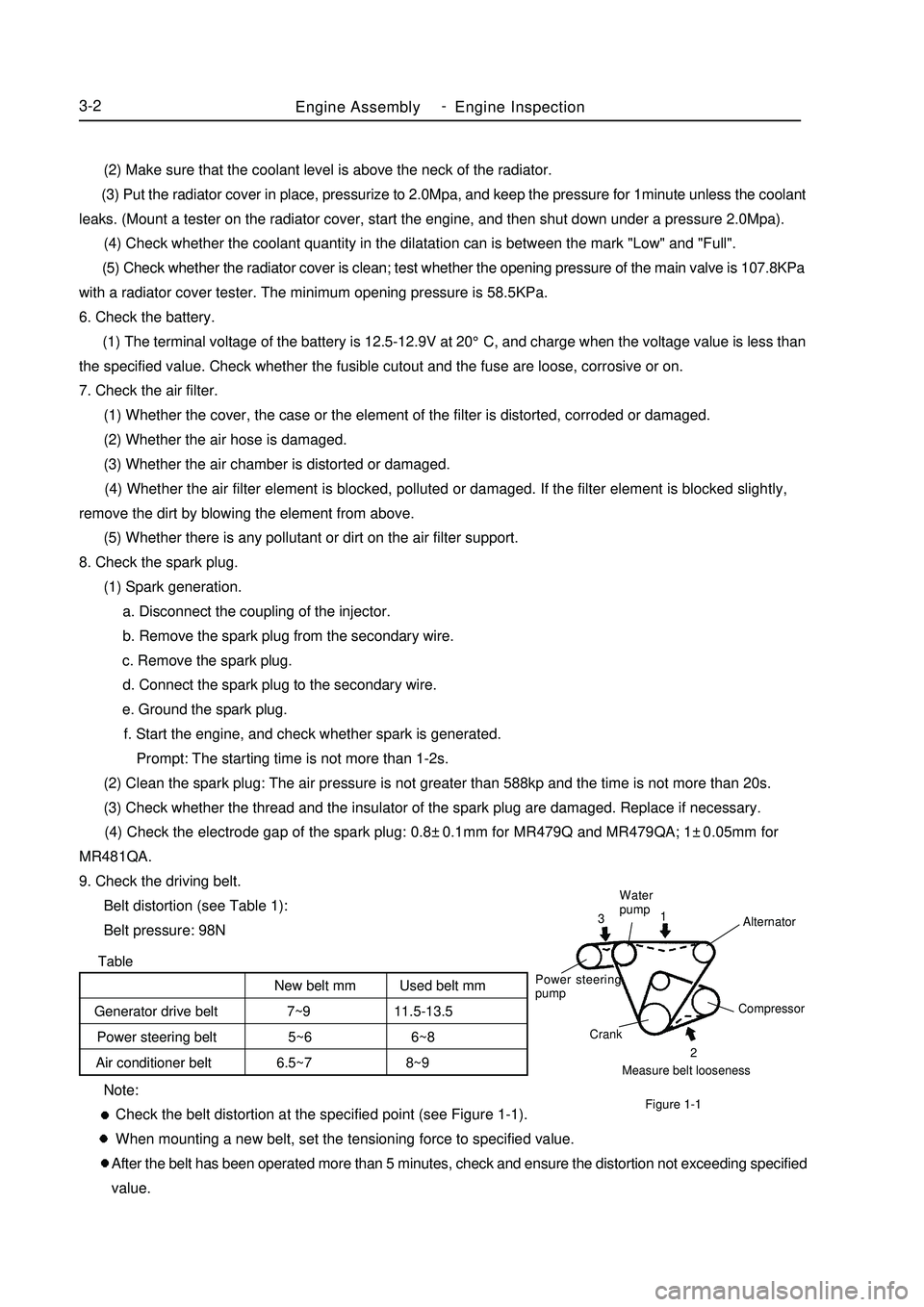
TableEngine AssemblyEngine Inspection3-2 Note:
Check the belt distortion at the specified point (see Figure 1-1).
When mounting a new belt, set the tensioning force to specified value.
After the belt has been operated more than 5 minutes, check and ensure the distortion not exceeding specified
value. (2) Make sure that the coolant level is above the neck of the radiator.
(3) Put the radiator cover in place, pressurize to 2.0Mpa, and keep the pressure for 1minute unless the coolant
leaks. (Mount a tester on the radiator cover, start the engine, and then shut down under a pressure 2.0Mpa).
(4) Check whether the coolant quantity in the dilatation can is between the mark "Low" and "Full".
(5) Check whether the radiator cover is clean; test whether the opening pressure of the main valve is 107.8KPa
with a radiator cover tester. The minimum opening pressure is 58.5KPa.
6. Check the battery.
(1) The terminal voltage of the battery is 12.5-12.9V at 20°C, and charge when the voltage value is less than
the specified value. Check whether the fusible cutout and the fuse are loose, corrosive or on.
7. Check the air filter.
(1) Whether the cover, the case or the element of the filter is distorted, corroded or damaged.
(2) Whether the air hose is damaged.
(3) Whether the air chamber is distorted or damaged.
(4) Whether the air filter element is blocked, polluted or damaged. If the filter element is blocked slightly,
remove the dirt by blowing the element from above.
(5) Whether there is any pollutant or dirt on the air filter support.
8. Check the spark plug.
(1) Spark generation.
a. Disconnect the coupling of the injector.
b. Remove the spark plug from the secondary wire.
c. Remove the spark plug.
d. Connect the spark plug to the secondary wire.
e. Ground the spark plug.
f. Start the engine, and check whether spark is generated.
Prompt: The starting time is not more than 1-2s.
(2) Clean the spark plug: The air pressure is not greater than 588kp and the time is not more than 20s.
(3) Check whether the thread and the insulator of the spark plug are damaged. Replace if necessary.
(4) Check the electrode gap of the spark plug: 0.8±0.1mm for MR479Q and MR479QA; 1±0.05mm for
MR481QA.
9. Check the driving belt.
Belt distortion (see Table 1):
Belt pressure: 98NMeasure belt loosenessCompressor
Crank Power steering
pumpWater
pump
Alternator2 1
3Figure 1-1New belt mm Used belt mm
Generator drive belt 7~9 11.5-13.5
Power steering belt 5~6 6~8
Air conditioner belt 6.5~7 8~9 -
Page 44 of 416
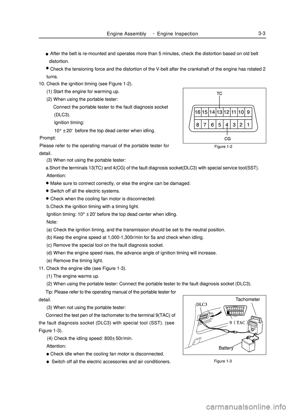
Figure 1-2
Figure 1-3Engine AssemblyEngine Inspection3-3 After the belt is re-mounted and operates more than 5 minutes, check the distortion based on old belt
distortion.
Check the tensioning force and the distortion of the V-belt after the crankshaft of the engine has rotated 2
turns.
10. Check the ignition timing (see Figure 1-2).
(1) Start the engine for warming up.
(2) When using the portable tester:
Connect the portable tester to the fault diagnosis socket
(DLC3).
Ignition timing:
before the top dead center when idling.
Prompt:
Please refer to the operating manual of the portable tester for
detail.
(3) When not using the portable tester:
a.Short the terminals 13(TC) and 4(CG) of the fault diagnosis socket(DLC3) with special service tool(SST).
Attention:
Make sure to connect correctly, or else the engine can be damaged.
Switch off all the electric systems.
Check when the cooling fan motor is disconnected.
b.Check the ignition timing with a timing light.
Ignition timing: 10°±20' before the top dead center when idling.
Note:
(a) Check the ignition timing, and the transmission should be set to the neutral position.
(b) Keep the engine speed at 1,000-1,300r/min for 5s and check when idling.
(c) Remove the special tool on the fault diagnosis socket.
(d) When the engine speed rises, the advance angle of ignition timing will increase.
(e) Remove the timing light.
11. Check the engine idle (see Figure 1-3).
(1) The engine warms up.
(2) When using the portable tester: Connect the portable tester to the fault diagnosis socket (DLC3).
Tip: Please refer to the operating manual of the portable tester for
detail.
(3) When not using the portable tester:
Connect the test pen of the tachometer to the terminal 9(TAC) of
the fault diagnosis socket (DLC3) with special tool (SST). (see
Figure 1-3).
(4) Check the idling speed: 800±50r/min.
Attention:
Check idle when the cooling fan motor is disconnected.
Switch off all the electric accessories and air conditioners.Tachometer
Battery10°±20' -
Page 90 of 416

Component ViewSection 2 Clutch PedalAdjustment1. Check and adjust the clutch pedal.
(1) Lift the carpet on the floor.
(2) Check the pedal’s height is proper.
Pedal's height from oil felt: 134.3-144.3mm
(3) Adjust the pedal's height.
Loosen the lock nut, and turn the bolt till the correct pedal's
height is reached, and then tighten the lock nut.
Torque: 16N.m
(4) Check whether the pedal's free travel and push bar travel are
proper.
a. Step the pedal down till a resistance appears.
Pedal's free stroke: 5-15mm
b. Step the pedal down lightly till the resistance increase a
little.
Push bar (on the pedals top) travel: 1.0-5.0mm
(5) Adjust the pedal's free travel and push bar travel.
a. Loosen the lock nut, and turn the push bar till the pedal's
free travel and push bar travel are proper.Clutch pedal bracket
Hex. flange nut37
Clutch pedal spring
Clutch pedal
bushing
Absorber
Clutch pedal cover Clutch pedal
Transimissin RodClutch master cylinder cone
U-connector bushingClutch pedal bushing Clutch Peader AxisClip12
Master cylinder
outtet pipesetSted Band ClampMaster cylinder
Inlet hoseHydranlic clutch hose
ÒLÓ Clip
Clutch hose Bracket
BoltClutch Control SystemClutch Pedal4-13Non-reusable parts
Multi-function lubeNm :Specified torquePedal height
adjustmentClutch
pedal Travel
Push travel &
free travel adjustment
pointPedal heightPedal free travel -
Page 145 of 416

Suspected Area
1. Steering knuckle (worn)
2. Swing arm ball stud pin joint (worn)
3. Intermediate shaft, sliding yoke (worn)
4. Front wheel bearing (worn)
5. Power steering gear assembly (worn)
1. Power steering pump fluid level (low)
2. Steering system ball joint (worn)
3. Power steering pump assembly (damaged)
4. Power steering gear assembly (damaged)Symptom
Excessive clearance
and play
Abnormal noise5. On-vehicle inspection1 Check steering wheel free play
(1) Stop vehicle and keep the tires straight ahead.
(2) Rotate the steering wheel slightly, check the steering wheel
free stroke.
Maximum free play: 30mmPower Steering System-Power Steering System4-68Max. free play
Page 150 of 416
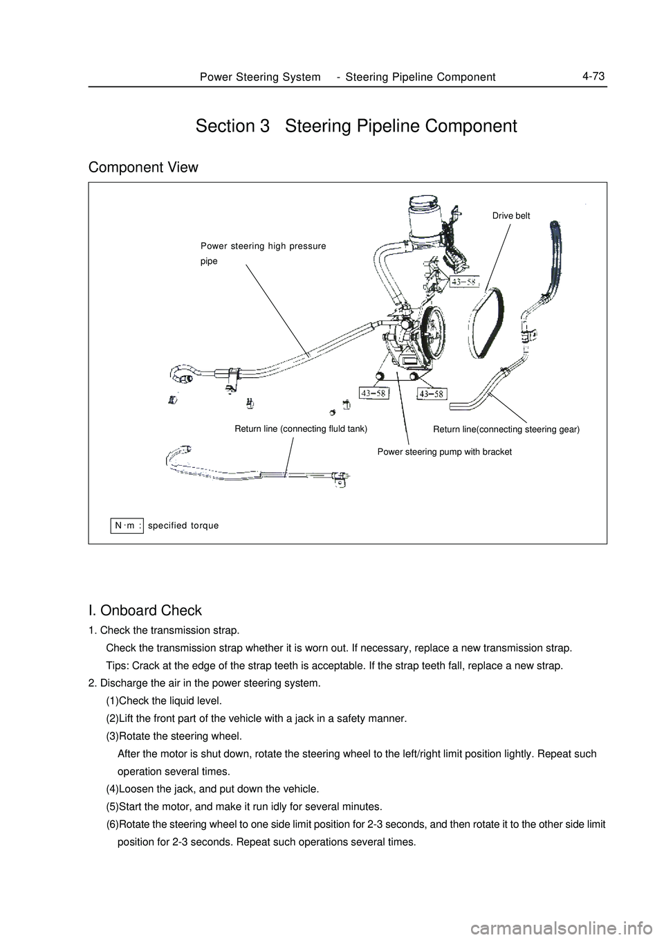
Power Steering System-Steering Pipeline Component4-73I. Onboard Check1. Check the transmission strap.
Check the transmission strap whether it is worn out. If necessary, replace a new transmission strap.
Tips: Crack at the edge of the strap teeth is acceptable. If the strap teeth fall, replace a new strap.
2. Discharge the air in the power steering system.
(1)Check the liquid level.
(2)Lift the front part of the vehicle with a jack in a safety manner.
(3)Rotate the steering wheel.
After the motor is shut down, rotate the steering wheel to the left/right limit position lightly. Repeat such
operation several times.
(4)Loosen the jack, and put down the vehicle.
(5)Start the motor, and make it run idly for several minutes.
(6)Rotate the steering wheel to one side limit position for 2-3 seconds, and then rotate it to the other side limit
position for 2-3 seconds. Repeat such operations several times.Section 3 Steering Pipeline ComponentComponent ViewPower steering high pressure
pipe
Return line (connecting fluld tank)
Power steering pump with bracketReturn line(connecting steering gear)Drive beltN.
m : specified torque
Page 159 of 416

Component ViewSection 3 Brake PedalBrake pedal bracket
Lubrication bushing
Handspike pin
Pad
Clip
Brake pedal Brake light bushing25Brake System -Brake Pedal4-82Brake master cylinder
handspike U-connector
Brake light switch
Brake pedal axis
Brake pedal return spring
Brake pedal pad
Specified torque
Non-reusable parts
Lithium soap-base glycol lube
Page 160 of 416
Adjustment1. Check and adjust the height of brake pedal.
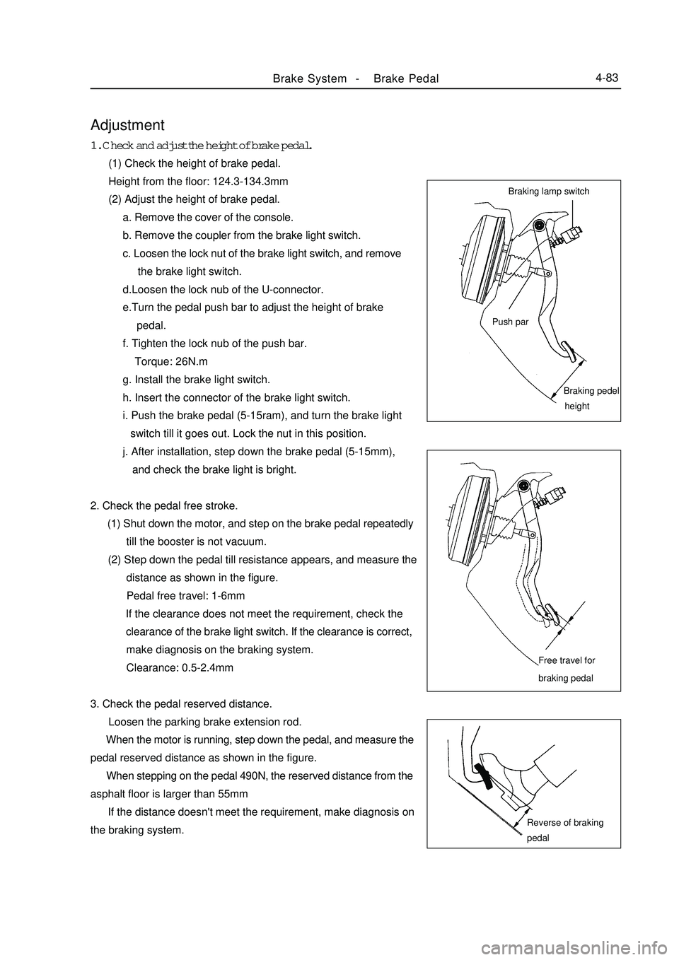
(1) Check the height of brake pedal.
Height from the floor: 124.3-134.3mm
(2) Adjust the height of brake pedal.
a. Remove the cover of the console.
b. Remove the coupler from the brake light switch.
c. Loosen the lock nut of the brake light switch, and remove
the brake light switch.
d.Loosen the lock nub of the U-connector.
e.Turn the pedal push bar to adjust the height of brake
pedal.
f. Tighten the lock nub of the push bar.
Torque: 26N.m
g. Install the brake light switch.
h. Insert the connector of the brake light switch.
i. Push the brake pedal (5-15ram), and turn the brake light
switch till it goes out. Lock the nut in this position.
j. After installation, step down the brake pedal (5-15mm),
and check the brake light is bright.
2. Check the pedal free stroke.
(1) Shut down the motor, and step on the brake pedal repeatedly
till the booster is not vacuum.
(2) Step down the pedal till resistance appears, and measure the
distance as shown in the figure.
Pedal free travel: 1-6mm
If the clearance does not meet the requirement, check the
clearance of the brake light switch. If the clearance is correct,
make diagnosis on the braking system.
Clearance: 0.5-2.4mm
3. Check the pedal reserved distance.
Loosen the parking brake extension rod.
When the motor is running, step down the pedal, and measure the
pedal reserved distance as shown in the figure.
When stepping on the pedal 490N, the reserved distance from the
asphalt floor is larger than 55mm
If the distance doesn't meet the requirement, make diagnosis on
the braking system.Brake System -Brake Pedal4-83Braking lamp switch
Push parBraking pedel
heightFree travel for
braking pedalReverse of braking
pedal