Light GEELY MK 2008 Owner's Manual
[x] Cancel search | Manufacturer: GEELY, Model Year: 2008, Model line: MK, Model: GEELY MK 2008Pages: 416, PDF Size: 25.19 MB
Page 161 of 416
1
2
3Brake System -Brake Pedal4-84Removal After the installation, check and adjust the height, free stroke and reserved distance of the brake pedal.
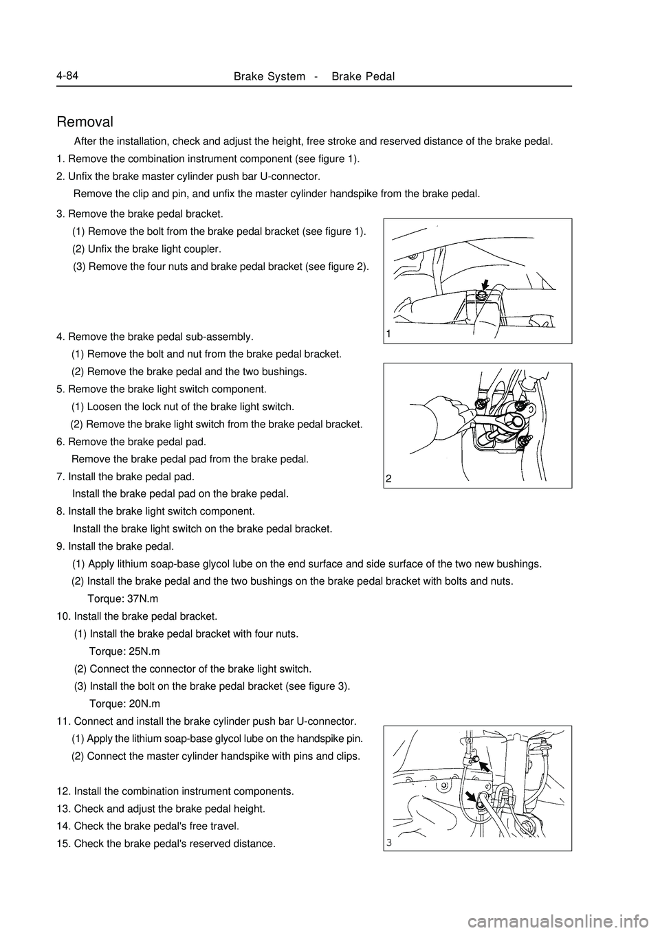
1. Remove the combination instrument component (see figure 1).
2. Unfix the brake master cylinder push bar U-connector.
Remove the clip and pin, and unfix the master cylinder handspike from the brake pedal.
3. Remove the brake pedal bracket.
(1) Remove the bolt from the brake pedal bracket (see figure 1).
(2) Unfix the brake light coupler.
(3) Remove the four nuts and brake pedal bracket (see figure 2).
4. Remove the brake pedal sub-assembly.
(1) Remove the bolt and nut from the brake pedal bracket.
(2) Remove the brake pedal and the two bushings.
5. Remove the brake light switch component.
(1) Loosen the lock nut of the brake light switch.
(2) Remove the brake light switch from the brake pedal bracket.
6. Remove the brake pedal pad.
Remove the brake pedal pad from the brake pedal.
7. Install the brake pedal pad.
Install the brake pedal pad on the brake pedal.
8. Install the brake light switch component.
Install the brake light switch on the brake pedal bracket.
9. Install the brake pedal.
(1) Apply lithium soap-base glycol lube on the end surface and side surface of the two new bushings.
(2) Install the brake pedal and the two bushings on the brake pedal bracket with bolts and nuts.
Torque: 37N.m
10. Install the brake pedal bracket.
(1) Install the brake pedal bracket with four nuts.
Torque: 25N.m
(2) Connect the connector of the brake light switch.
(3) Install the bolt on the brake pedal bracket (see figure 3).
Torque: 20N.m
11. Connect and install the brake cylinder push bar U-connector.
(1) Apply the lithium soap-base glycol lube on the handspike pin.
(2) Connect the master cylinder handspike with pins and clips.
12. Install the combination instrument components.
13. Check and adjust the brake pedal height.
14. Check the brake pedal's free travel.
15. Check the brake pedal's reserved distance.
Page 164 of 416

Repair1. Discharge the brake fluid.
Note: Never spray the brake fluid on the paint surface, otherwise
wash it immediately.
2. Remove the brake master cylinder.
(1) Pull out the connector of the level alarm light switch.
(2) Slide the clip, and pull out #1 clutch storage tank pipe (manual
transaxle).
(3) Remove the two brake pipes from the brake master cylinder
with special tool.(with ABS)
(4) Remove the three brake pipes from the brake master cylinder
accessory with special tool. (without ABS)
(5) Remove the two lock nuts, and pull out the brake master
pump.
3. Remove the storage tank.
(1) Put the brake master cylinder on the bench clamp.
(2) Remove the pin from the brake master cylinder body with
punch and hammer.
(3) Pull out the Brake fluid reservoir.
(4) Remove the cover and strainer from the storage tank.
(5) Remove the storage tank and the two hole connectors.
4. Remove the brake master cylinder.
(1) Put the brake master cylinder on the bench clamp.
(2) Remove the O-ring.
(3) Push the piston with hand, and remove the snap ring with
snap ring pliers.Brake System -Brake Master Cylinder Assembly4-87With ABS:
Without ABS
Page 190 of 416
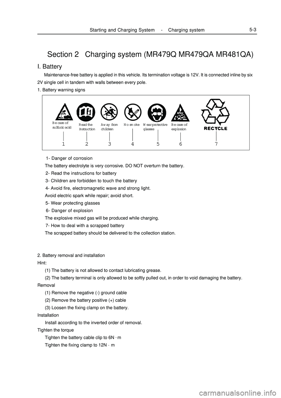
Section 2 Charging system (MR479Q MR479QA MR481QA) 1- Danger of corrosion
The battery electrolyte is very corrosive. DO NOT overturn the battery.
2- Read the instructions for battery
3- Children are forbidden to touch the battery
4- Avoid fire, electromagnetic wave and strong light.
Avoid electric spark while repair; avoid short.
5- Wear protecting glasses
6- Danger of explosion
The explosive mixed gas will be produced while charging.
7- How to deal with a scrapped battery
The scrapped battery should be delivered to the collection station.
2. Battery removal and installation
Hint:
(1) The battery is not allowed to contact lubricating grease.
(2) The battery terminal is only allowed to be softly pulled out, in order to void damaging the battery.
Removal
(1) Remove the negative (-) ground cable
(2) Remove the battery positive (+) cable
(3) Loosen the fixing clamp on the battery.
Installation
Install according to the inverted order of removal.
Tighten the torque
Tighten the battery cable clip to 6N.
m
Tighten the fixing clamp to 12N.
mI. Battery Maintenance-free battery is applied in this vehicle. Its termination voltage is 12V. It is connected inline by six
2V single cell in tandem with walls between every pole.
1. Battery warning signsStarting and Charging System -Charging system5-3Be care of
sulfuric acidRead the
instructionAway from
childrenNo smoke Wear protective
glassesBe care of
explosion1234 56 7
Page 191 of 416
II. Charging system inspection1. Check battery working voltage
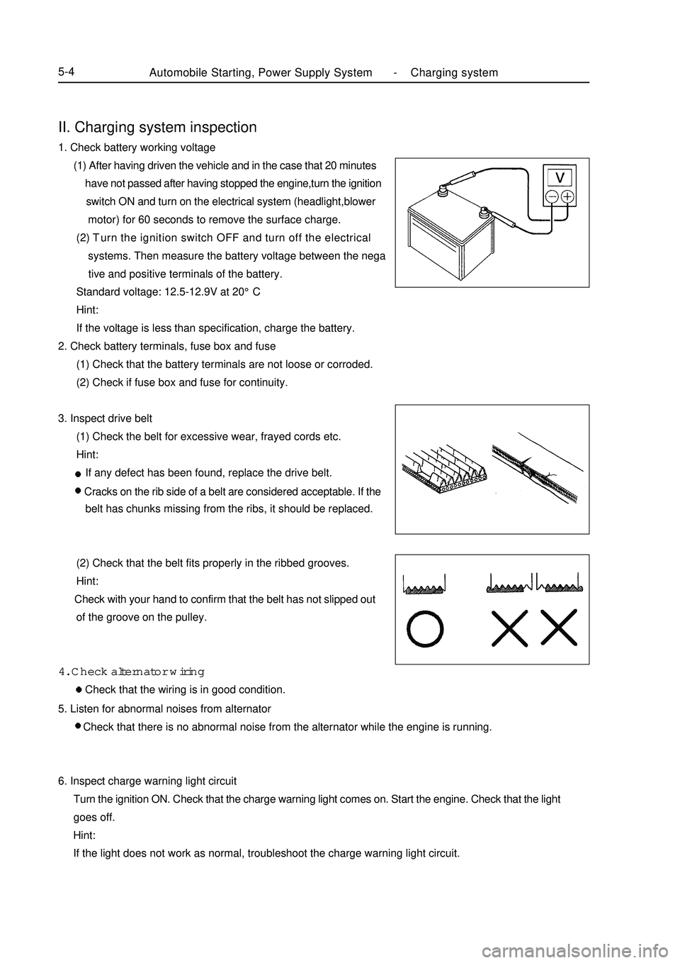
(1) After having driven the vehicle and in the case that 20 minutes
have not passed after having stopped the engine,turn the ignition
switch ON and turn on the electrical system (headlight,blower
motor) for 60 seconds to remove the surface charge.
(2) Turn the ignition switch OFF and turn off the electrical
systems. Then measure the battery voltage between the nega
tive and positive terminals of the battery.
Standard voltage: 12.5-12.9V at 20°C
Hint:
If the voltage is less than specification, charge the battery.
2. Check battery terminals, fuse box and fuse
(1) Check that the battery terminals are not loose or corroded.
(2) Check if fuse box and fuse for continuity.
3. Inspect drive belt
(1) Check the belt for excessive wear, frayed cords etc.
Hint:
If any defect has been found, replace the drive belt.
Cracks on the rib side of a belt are considered acceptable. If the
belt has chunks missing from the ribs, it should be replaced.
(2) Check that the belt fits properly in the ribbed grooves.
Hint:
Check with your hand to confirm that the belt has not slipped out
of the groove on the pulley.
4. Check alternator wiring
Check that the wiring is in good condition.Automobile Starting, Power Supply System -Charging system5-45. Listen for abnormal noises from alternator
Check that there is no abnormal noise from the alternator while the engine is running.
6. Inspect charge warning light circuit
Turn the ignition ON. Check that the charge warning light comes on. Start the engine. Check that the light
goes off.
Hint:
If the light does not work as normal, troubleshoot the charge warning light circuit.
Page 192 of 416
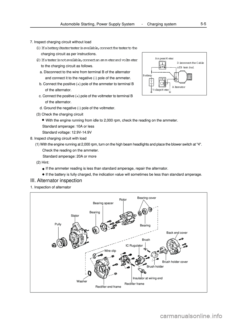
Automobile Starting, Power Supply System -Charging system5-57. Inspect charging circuit without load
(1) If a battery/starter tester is available, connect the tester to the
charging circuit as per instructions.
(2) If a tester is not available, connect an ammeter and voltmeter
to the charging circuit as follows.
a. Disconnect to the wire from terminal B of the alternator
and connect it to the negative (-) pole of the ammeter.
b. Connect the positive (+) pole of the ammeter to terminal B
of the alternator.
c. Connect the positive (+) pole of the voltmeter to terminal B
of the alternator.
d. Ground the negative (-) pole of the voltmeter.
(3) Check the charging circuit
With the engine running from idle to 2,000 rpm, check the reading on the ammeter.
Standard amperage: 10A or less
Standard voltage: 12.9V-14.9V
8. Inspect charging circuit with load
(1) With the engine running at 2,000 rpm, turn on the high beam headlights and place the blower switch at "4".
Check the reading on the ammeter.
Standard amperage: 20A or more
(2) Hint:
If the ammeter reading is less than standard amperage, repair the alternator.
If the battery is fully charged, the indication value will sometimes be less than standard amperage.III. Alternator inspection1. Inspection of alternatorPullyStatorBearingBearing spacerRotorBearing cover
Bearing
Wire clipBrush
Washer
Rectifier end frameRectifier frameInsulator at wiring endBrush holderBrush holder coverBack end coverIC RugulatorAmpere Meter
BatteryVoltage MeterAlternatorDisconnect the Cable
of B terminal
Page 196 of 416
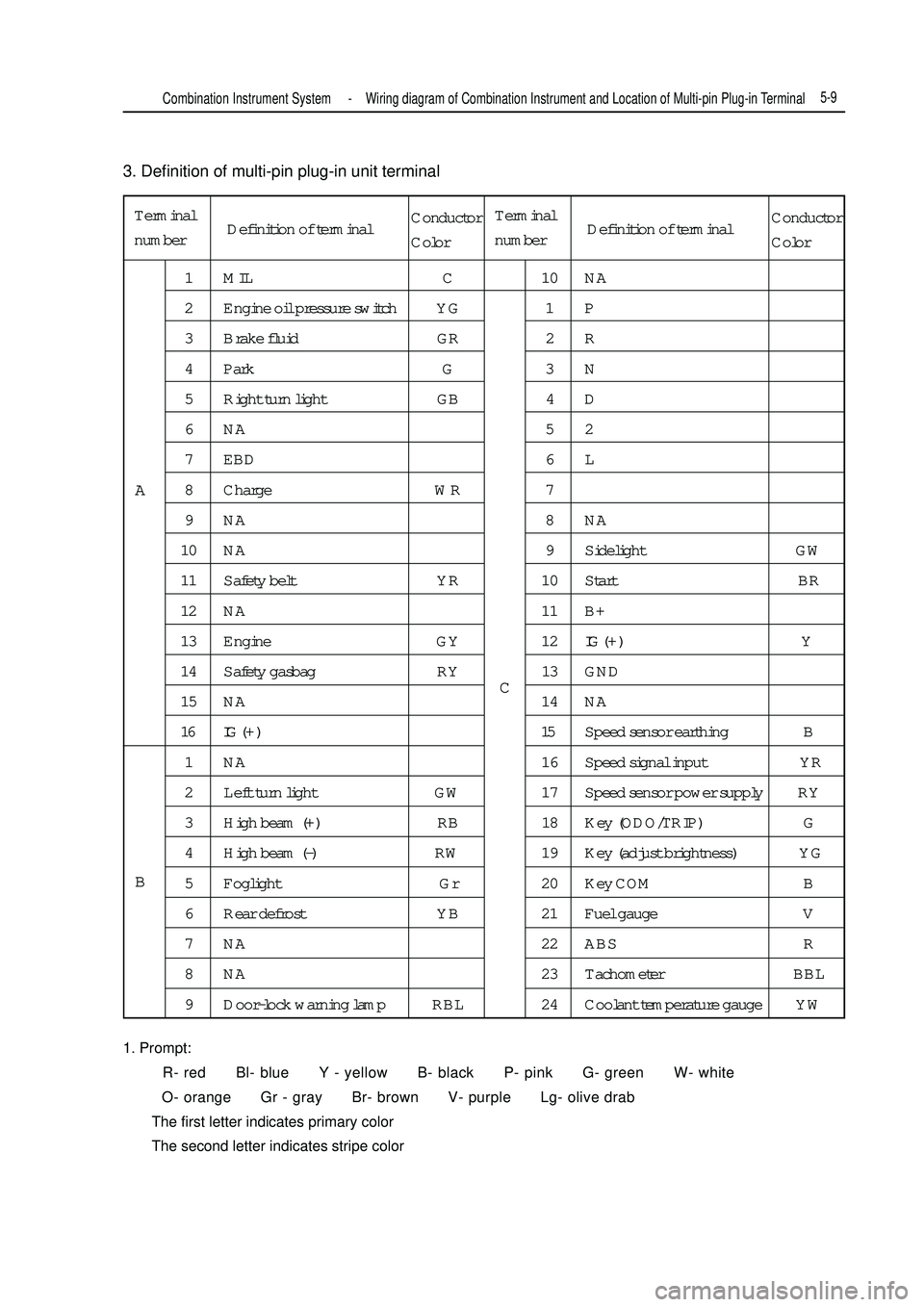
3. Definition of multi-pin plug-in unit terminal
1. Prompt:
R- red Bl- blue Y - yellow B- black P- pink G- green W- white
O- orange Gr - gray Br- brown V- purple Lg- olive drab
The first letter indicates primary color
The second letter indicates stripe colorTerminal
number1 MIL C 10 NA
2 Engine oil pressure switch YG 1 P
3 Brake fluid GR 2 R
4 Park G 3 N
5 Right turn light GB 4 D
6NA 52
7 EBD 6 L
8 Charge WR 7
9NA 8NA
10 NA 9 Sidelight GW
11 Safety belt YR 10 Start BR
12 NA 11 B+
13 Engine GY 12IG ( + ) Y
14 Safety gasbag RY 13 GND
15 NA 14 NA
16 IG ( + ) 15Speed sensor earthing B
1 NA 16 Speed signal input YR
2 Left turn light GW 17 Speed sensor power supply RY
3 High beam (+) RB 18 Key (ODO/TRIP) G
4 High beam (-) RW 19 Key (adjust brightness) YG
5 Foglight Gr 20 Key COM B
6 Rear defrost YB 21 Fuel gauge V
7 NA 22 ABS R
8 NA 23 Tachometer BBL
9 Door-lock warning lamp RBL 24 Coolant temperature gauge YWA
BCCombination Instrument System -Wiring diagram of Combination Instrument and Location of Multi-pin Plug-in Terminal5-9Definition of terminalConductor
ColorTerminal
numberDefinition of terminalConductor
Color
Page 197 of 416
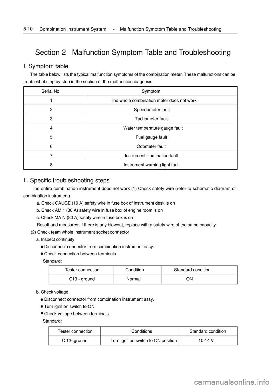
Serial No. Symptom
1 The whole combination meter does not work
2 Speedometer fault
3 Tachometer fault
4 Water temperature gauge fault
5 Fuel gauge fault
6 Odometer fault
7 Instrument illumination fault
8 Instrument warning light fault
Tester connection Condition Standard condition
C13 - ground Normal ONSection 2 Malfunction Symptom Table and TroubleshootingI. Symptom table The table below lists the typical malfunction symptoms of the combination meter. These malfunctions can be
troubleshot step by step in the section of the malfunction diagnosis.Tester connection Conditions Standard condition
C 12- ground Turn ignition switch to ON position 10-14 VCombination Instrument System -Malfunction Symptom Table and Troubleshooting5-10II. Specific troubleshooting steps The entire combination instrument does not work (1) Check safety wire (refer to schematic diagram of
combination instrument)
a. Check GAUGE (10 A) safety wire in fuse box of instrument desk is on
b. Check AM 1 (30 A) safety wire in fuse box of engine room is on
c. Check MAIN (80 A) safety wire in fuse box is on
Result and measures: if there is any blowout, replace with a safety wire of the same capacity
(2) Check team whole instrument socket connector
a. Inspect continuity
Disconnect connector from combination instrument assy.
Check connection between terminals
Standard:
b. Check voltage
Disconnect connector from combination instrument assy.
Turn ignition switch to ON
Check voltage between terminals
Standard:
Page 203 of 416

Suspected area
1. Wiring harness or connector
2. ECM
3. Combination instrument assy.
1. Wiring harness or connector
2. Alternator
3. Combination instrument assy.
1. Wiring harness or connector
2. Manual brake switch
3. Combination instrument assy.
1. Wiring harness or connector
2. Brake fluid level switch
3. Combination instrument assy.
1. Wiring harness or connector
2. ABS ECU or ABS warning lamp driving module
3. Combination instrument assy.
1. Wiring harness or connector
2. Airbag ECU controller
3. Combination instrument assy.
1. Wiring harness or connector
2. Airbag ECU controller
3. Combination instrument assy.
1. Wiring harness or connector
2. Front head light dimmer switch
3. Combination instrument assy.
1. Wiring harness or connector
2. Front head light dimmer switch
3. Combination instrument assy.
1. Wiring harness or connector
2. Rear defrost switch
3. Combination instrument assy. 8. Warning lamp fails
Symptom
Check that engine warning lamp does not
illuminate
Charge warning lamp does not illuminate
Park braking warning lamp does not
illuminate
Brake failure warning lamp does not
illuminate
ABS warning lamp does not illuminate
SRS warning lamp does not illuminate
Passenger's airbag indicator lamp does
not illuminate
High beam indicator lamp does not
illuminate
Rear foglight indicator lamp does not
illuminate
Rear defrost indicator lamp does not
illuminate5-16Combination Instrument System -Malfunction Symptom Table and Troubleshooting
Page 206 of 416
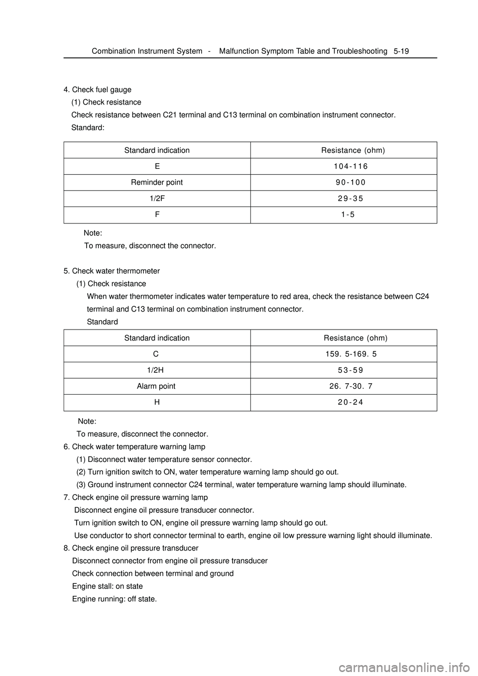
Note:
To measure, disconnect the connector.
5. Check water thermometer
(1) Check resistance
When water thermometer indicates water temperature to red area, check the resistance between C24
terminal and C13 terminal on combination instrument connector.
Standard 4. Check fuel gauge
(1) Check resistance
Check resistance between C21 terminal and C13 terminal on combination instrument connector.
Standard:5-19Standard indication
E
Reminder point
1/2F
FResistance (ohm)
104-116
90-100
29-35
1-5
Standard indication
C
1/2H
Alarm point
HResistance (ohm)
159. 5-169. 5
53-59
26. 7-30. 7
20-24
Note:
To measure, disconnect the connector.
6. Check water temperature warning lamp
(1) Disconnect water temperature sensor connector.
(2) Turn ignition switch to ON, water temperature warning lamp should go out.
(3) Ground instrument connector C24 terminal, water temperature warning lamp should illuminate.
7. Check engine oil pressure warning lamp
Disconnect engine oil pressure transducer connector.
Turn ignition switch to ON, engine oil pressure warning lamp should go out.
Use conductor to short connector terminal to earth, engine oil low pressure warning light should illuminate.
8. Check engine oil pressure transducer
Disconnect connector from engine oil pressure transducer
Check connection between terminal and ground
Engine stall: on state
Engine running: off state.Combination Instrument System -Malfunction Symptom Table and Troubleshooting
Page 207 of 416

5-209. Check park warning lamp
(1) Disconnect connector from park switch
(2) Turn ignition switch to ON, park brake warning lamp should go out.
(3) Use conductor to short connector terminal to ground, park brake warning lamp should illuminate.
10. Check park switch
(1) Disconnect connector from park switch
(2) Pull up manual brake, check whether its terminal is connected with ground
Pull up manual brake: on
Manual brake release: off
11. Brake fluid level warning lamp
(1) Disconnect connector from brake fluid level sensor
(2) Turn ignition switch to ON, brake fluid level warning lamp should go out.
(3) Use conductor to connect its connector terminal wiring harness terminals directly, brake fluid level
warning lamp should illuminate.
12. Check brake fluid level warning switch
(1) Remove tank cap
(2) Disconnect connector from tank
(3) Check whether terminals are connected.
Floater on top: off
(4) Use sucker to suck out liquid from tank
(5) Check whether terminals are connected.
Floater down: on state
(6) Pour liquid back into tank
13. Rear defrost indicator lamp
(1) Turn ignition switch to ON, and start up engine
(2) Push down defrost switch, now rear defrost indicator lamp should illuminate
(3) Turn ignition switch to OFF, rear defrost indicator lamp should go out
14. Rear foglight indicator lamp
When rear foglight illuminates, rear foglight indicator lamp should illuminate, now A5 terminal should be high
potential.
15. Safety belt warning indicator lamp
(1) Disconnect safety belt switch connector from driver side, now safety belt warning indicator lamp should
go out.
(2) Short connector terminal to ground, safety belt warning indicator lamp should illuminate.Combination Instrument System -Malfunction Symptom Table and Troubleshooting