belt GEELY MK 2008 User Guide
[x] Cancel search | Manufacturer: GEELY, Model Year: 2008, Model line: MK, Model: GEELY MK 2008Pages: 416, PDF Size: 25.19 MB
Page 44 of 416
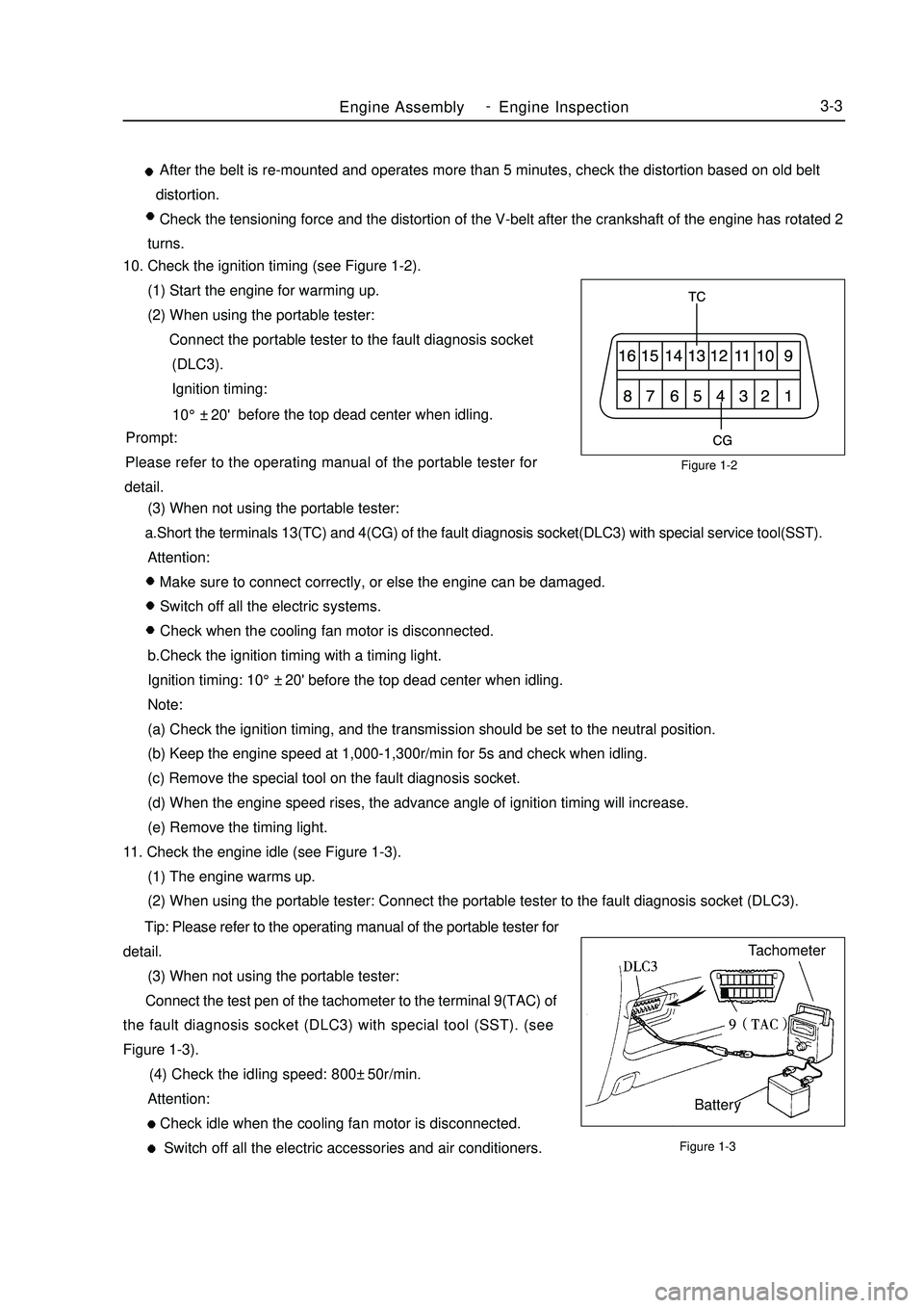
Figure 1-2
Figure 1-3Engine AssemblyEngine Inspection3-3 After the belt is re-mounted and operates more than 5 minutes, check the distortion based on old belt
distortion.
Check the tensioning force and the distortion of the V-belt after the crankshaft of the engine has rotated 2
turns.
10. Check the ignition timing (see Figure 1-2).
(1) Start the engine for warming up.
(2) When using the portable tester:
Connect the portable tester to the fault diagnosis socket
(DLC3).
Ignition timing:
before the top dead center when idling.
Prompt:
Please refer to the operating manual of the portable tester for
detail.
(3) When not using the portable tester:
a.Short the terminals 13(TC) and 4(CG) of the fault diagnosis socket(DLC3) with special service tool(SST).
Attention:
Make sure to connect correctly, or else the engine can be damaged.
Switch off all the electric systems.
Check when the cooling fan motor is disconnected.
b.Check the ignition timing with a timing light.
Ignition timing: 10°±20' before the top dead center when idling.
Note:
(a) Check the ignition timing, and the transmission should be set to the neutral position.
(b) Keep the engine speed at 1,000-1,300r/min for 5s and check when idling.
(c) Remove the special tool on the fault diagnosis socket.
(d) When the engine speed rises, the advance angle of ignition timing will increase.
(e) Remove the timing light.
11. Check the engine idle (see Figure 1-3).
(1) The engine warms up.
(2) When using the portable tester: Connect the portable tester to the fault diagnosis socket (DLC3).
Tip: Please refer to the operating manual of the portable tester for
detail.
(3) When not using the portable tester:
Connect the test pen of the tachometer to the terminal 9(TAC) of
the fault diagnosis socket (DLC3) with special tool (SST). (see
Figure 1-3).
(4) Check the idling speed: 800±50r/min.
Attention:
Check idle when the cooling fan motor is disconnected.
Switch off all the electric accessories and air conditioners.Tachometer
Battery10°±20' -
Page 48 of 416
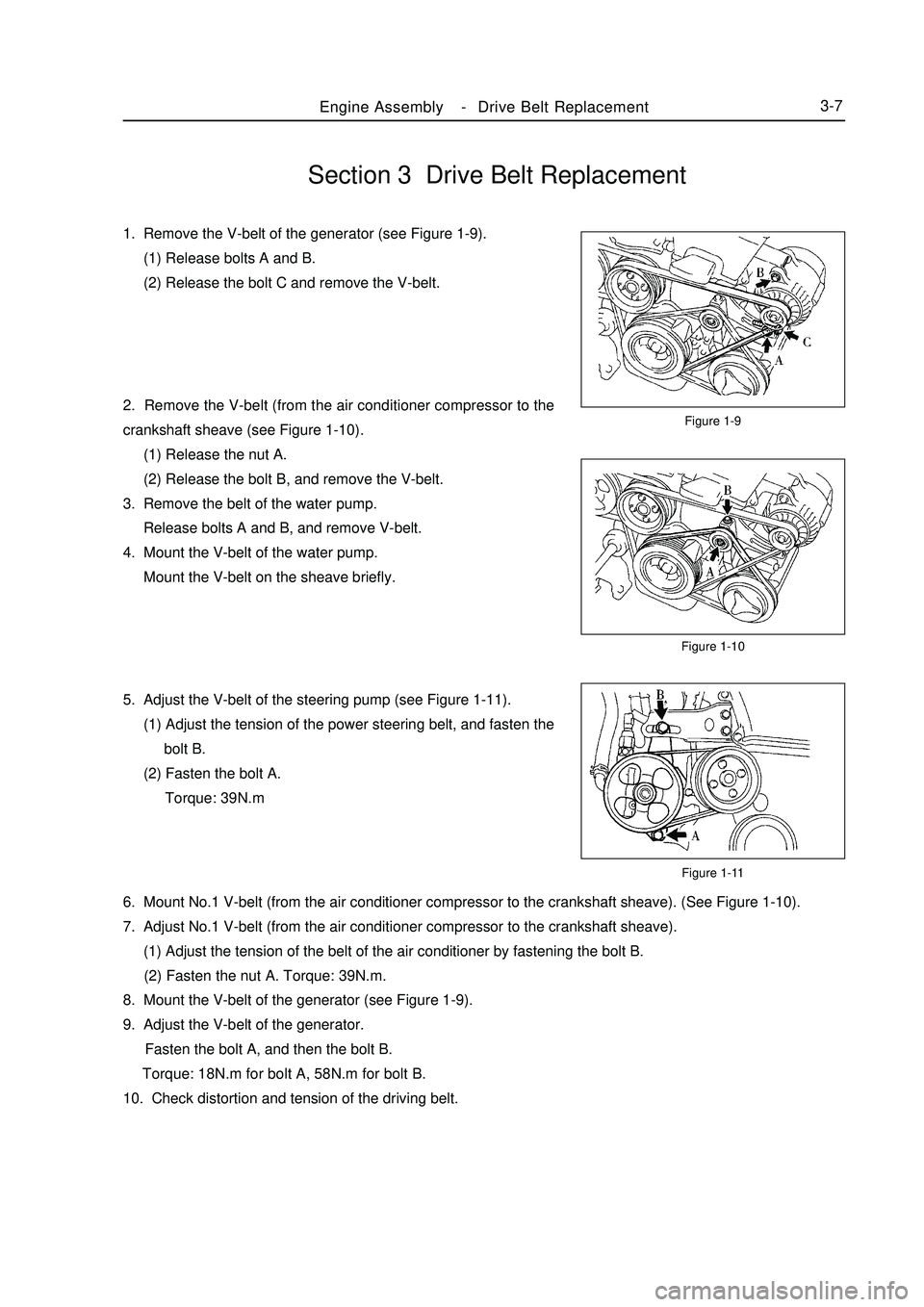
Section 3 Drive Belt Replacement1. Remove the V-belt of the generator (see Figure 1-9).
(1) Release bolts A and B.
(2) Release the bolt C and remove the V-belt.
2. Remove the V-belt (from the air conditioner compressor to the
crankshaft sheave (see Figure 1-10).
(1) Release the nut A.
(2) Release the bolt B, and remove the V-belt.
3. Remove the belt of the water pump.
Release bolts A and B, and remove V-belt.
4. Mount the V-belt of the water pump.
Mount the V-belt on the sheave briefly.
5. Adjust the V-belt of the steering pump (see Figure 1-11).
(1) Adjust the tension of the power steering belt, and fasten the
bolt B.
(2) Fasten the bolt A.
Torque: 39N.mFigure 1-9
Figure 1-10
Figure 1-11Engine AssemblyDrive Belt Replacement3-76. Mount No.1 V-belt (from the air conditioner compressor to the crankshaft sheave). (See Figure 1-10).
7. Adjust No.1 V-belt (from the air conditioner compressor to the crankshaft sheave).
(1) Adjust the tension of the belt of the air conditioner by fastening the bolt B.
(2) Fasten the nut A. Torque: 39N.m.
8. Mount the V-belt of the generator (see Figure 1-9).
9. Adjust the V-belt of the generator.
Fasten the bolt A, and then the bolt B.
Torque: 18N.m for bolt A, 58N.m for bolt B.
10. Check distortion and tension of the driving belt. -
Page 50 of 416
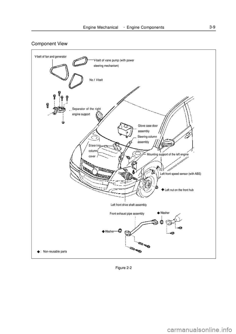
Component ViewFigure 2-2Engine MechanicalEngine Components3-9V-belt of fan and generator
V-belt of vane pump (with power
steering mechanism)
No.1 V-belt
Glove case door
assemblyFront exhaust pipe assemblySeparator of the right
engine support: Non-reusable partsLeft front drive shaft assemblyLeft nut on the front hubSteering
column
coverSteering column
assembly
Mounting support of the left engineLeft front speed sensor (with ABS)
Washer
Washer -
Page 52 of 416
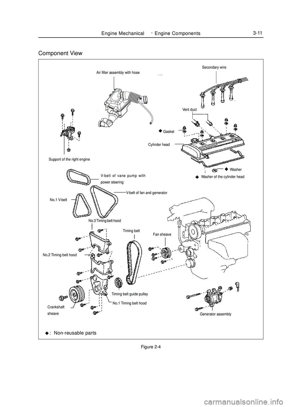
Component ViewFigure 2-4Air filter assembly with hoseEngine MechanicalEngine Components3-11V-belt of vane pump with
power steering Support of the right engine
V-belt of fan and generator
No.1 V-belt
No.3 Timing belt hood
No.2 Timing belt hood
No.1 Timing belt hoodFan sheaveSecondary wireWasher of the cylinder headCylinder headVent duct
Gasket
Washer
Timing belt
Timing belt guide pulley
Crankshaft
sheave
Generator assembly: Non-reusable parts -
Page 72 of 416
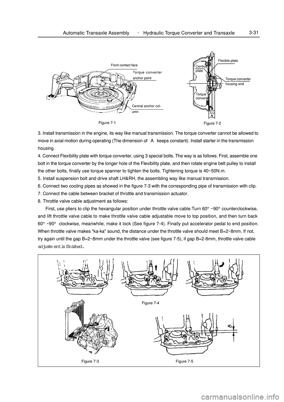
Figure 7-3Automatic Transaxle Assembly Hydraulic Torque Converter and Transaxle3-31Figure 7-5 Figure 7-4Figure 7-1
Figure 7-23. Install transmission in the engine, its way like manual transmission. The torque converter cannot be allowed to
move in axial motion during operating (The dimension of A keeps constant). Install starter in the transmission
housing.
4. Connect Flexibility plate with torque converter, using 3 special bolts. The way is as follows. First, assemble one
bolt in the torque converter by the longer hole of the Flexibility plate, and then rotate engine belt pulley to install
the other bolts, finally use torque spanner to tighten the bolts. Tightening torque is 40~50N.m.
5. Install suspension bolt and drive shaft LH&RH, the assembling way like manual transmission.
6. Connect two cooling pipes as showed in the figure 7-3 with the corresponding pipe of transmission with clip.
7. Connect the cable between bracket of throttle and transmission actuator.
8. Throttle valve cable adjustment as follows:
First, use pliers to clip the hexangular position under throttle valve cable.Turn 60°~90°counterclockwise,
and lift throttle valve cable to make throttle valve cable adjustable move to top position, and then turn back
60°~90° clockwise, meanwhile, make it lock (See figure 7-4). Finally put accelerator pedal to end position.
When throttle valve makes "ka-ka" sound, the distance under the throttle valve should meet B=2~8mm. If not,
try again until the gap B=2~8mm under the throttle valve (see figure 7-5), if gap B=2-8mm, throttle valve cable
adjustment is finished.Central
plateFlexible plate
Torque converter
housing end
Torque
converterFront contact face
Torque converter
anchor point
Central anchor col-
umn -
Page 137 of 416
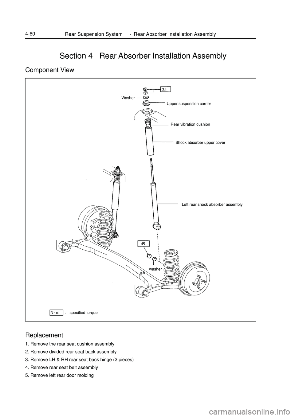
Section 4 Rear Absorber Installation AssemblyComponent ViewReplacement1. Remove the rear seat cushion assembly
2. Remove divided rear seat back assembly
3. Remove LH & RH rear seat back hinge (2 pieces)
4. Remove rear seat belt assembly
5. Remove left rear door moldingUpper suspension carrier
Rear vibration cushion
Shock absorber upper cover WasherLeft rear shock absorber assemblyRear Suspension System-Rear Absorber Installation Assembly4-60specified torqueN.
m :washer
Page 150 of 416
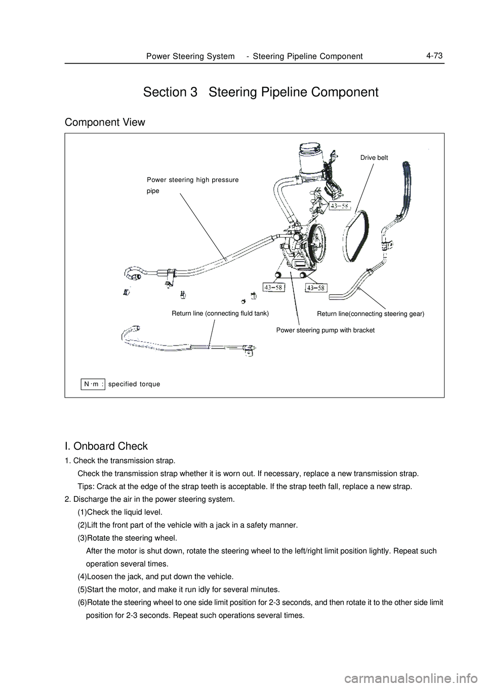
Power Steering System-Steering Pipeline Component4-73I. Onboard Check1. Check the transmission strap.
Check the transmission strap whether it is worn out. If necessary, replace a new transmission strap.
Tips: Crack at the edge of the strap teeth is acceptable. If the strap teeth fall, replace a new strap.
2. Discharge the air in the power steering system.
(1)Check the liquid level.
(2)Lift the front part of the vehicle with a jack in a safety manner.
(3)Rotate the steering wheel.
After the motor is shut down, rotate the steering wheel to the left/right limit position lightly. Repeat such
operation several times.
(4)Loosen the jack, and put down the vehicle.
(5)Start the motor, and make it run idly for several minutes.
(6)Rotate the steering wheel to one side limit position for 2-3 seconds, and then rotate it to the other side limit
position for 2-3 seconds. Repeat such operations several times.Section 3 Steering Pipeline ComponentComponent ViewPower steering high pressure
pipe
Return line (connecting fluld tank)
Power steering pump with bracketReturn line(connecting steering gear)Drive beltN.
m : specified torque
Page 151 of 416
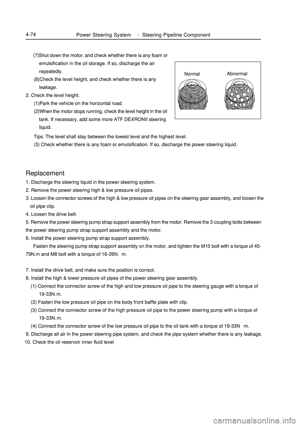
Power Steering System-
Steering Pipeline Component4-74 (7)Shut down the motor, and check whether there is any foam or
emulsification in the oil storage. If so, discharge the air
repeatedly.
(8)Check the level height, and check whether there is any
leakage.
2. Check the level height.
(1)Park the vehicle on the horizontal road.
(2)When the motor stops running, check the level height in the oil
tank. If necessary, add some more ATF DEXRONII steering
liquid.Replacement1. Discharge the steering liquid in the power steering system.
2. Remove the power steering high & low pressure oil pipes.
3. Loosen the connector screws of the high & low pressure oil pipes on the steering gear assembly, and loosen the
oil pipe clip.
4. Loosen the drive belt.
5. Remove the power steering pump strap support assembly from the motor. Remove the 3 coupling bolts between
the power steering pump strap support assembly and the motor.
6. Install the power steering pump strap support assembly.
Fasten the steering pump strap support assembly on the motor, and tighten the M10 bolt with a torque of 45-
79N.m and M8 bolt with a torque of 16-26N.m.
7. Install the drive belt, and make sure the position is correct.
8. Install the high & lower pressure oil pipes of the power steering gear assembly.
(1) Connect the connector screw of the high and low pressure oil pipe to the steering gauge with a torque of
19-33N.m.
(2) Fasten the low pressure oil pipe on the body front baffle plate with clip.
(3) Connect the connector screw of the high pressure oil pipe to the power steering pump with a torque of
19-33N.m.
(4) Connect the connector screw of the low pressure oil pipe to the oil tank with a torque of 19-33N.
m.
9. Discharge all air in the power steering pipe system, and check the pipe system whether there is any leakage.
10. Check the oil reservoir inner fluid level Tips: The level shall stay between the lowest level and the highest level.
(3) Check whether there is any foam or emulsification. If so, discharge the power steering liquid.NormalAbnormal
Page 191 of 416
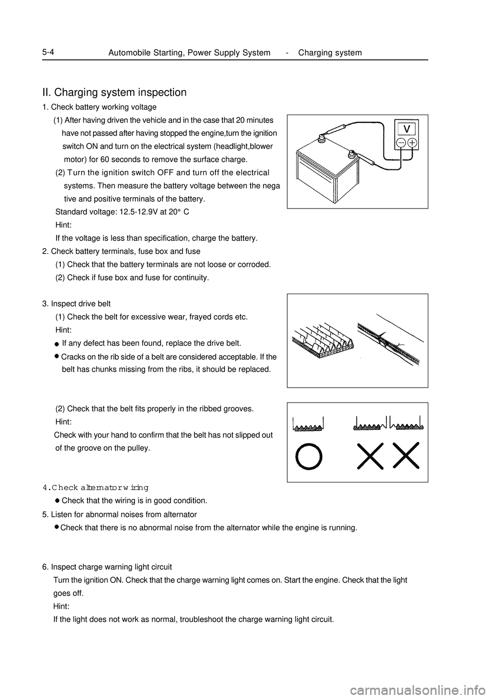
II. Charging system inspection1. Check battery working voltage
(1) After having driven the vehicle and in the case that 20 minutes
have not passed after having stopped the engine,turn the ignition
switch ON and turn on the electrical system (headlight,blower
motor) for 60 seconds to remove the surface charge.
(2) Turn the ignition switch OFF and turn off the electrical
systems. Then measure the battery voltage between the nega
tive and positive terminals of the battery.
Standard voltage: 12.5-12.9V at 20°C
Hint:
If the voltage is less than specification, charge the battery.
2. Check battery terminals, fuse box and fuse
(1) Check that the battery terminals are not loose or corroded.
(2) Check if fuse box and fuse for continuity.
3. Inspect drive belt
(1) Check the belt for excessive wear, frayed cords etc.
Hint:
If any defect has been found, replace the drive belt.
Cracks on the rib side of a belt are considered acceptable. If the
belt has chunks missing from the ribs, it should be replaced.
(2) Check that the belt fits properly in the ribbed grooves.
Hint:
Check with your hand to confirm that the belt has not slipped out
of the groove on the pulley.
4. Check alternator wiring
Check that the wiring is in good condition.Automobile Starting, Power Supply System -Charging system5-45. Listen for abnormal noises from alternator
Check that there is no abnormal noise from the alternator while the engine is running.
6. Inspect charge warning light circuit
Turn the ignition ON. Check that the charge warning light comes on. Start the engine. Check that the light
goes off.
Hint:
If the light does not work as normal, troubleshoot the charge warning light circuit.
Page 193 of 416
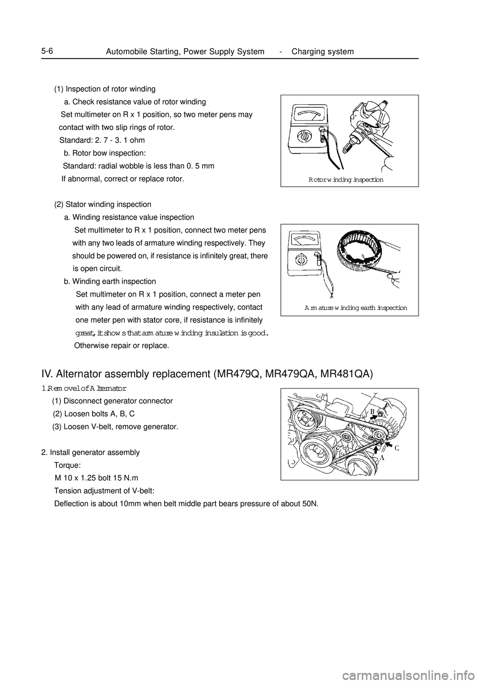
(1) Inspection of rotor winding
a. Check resistance value of rotor winding
Set multimeter on R x 1 position, so two meter pens may
contact with two slip rings of rotor.
Standard: 2. 7 - 3. 1 ohm
b. Rotor bow inspection:
Standard: radial wobble is less than 0. 5 mm
If abnormal, correct or replace rotor.
(2) Stator winding inspection
a. Winding resistance value inspection
Set multimeter to R x 1 position, connect two meter pens
with any two leads of armature winding respectively. They
should be powered on, if resistance is infinitely great, there
is open circuit.
b. Winding earth inspection
Set multimeter on R x 1 position, connect a meter pen
with any lead of armature winding respectively, contact
one meter pen with stator core, if resistance is infinitely
great, it shows that armature winding insulation is good.
Otherwise repair or replace.Automobile Starting, Power Supply System -Charging system5-6IV. Alternator assembly replacement (MR479Q, MR479QA, MR481QA)1.Removel of Alternator
(1) Disconnect generator connector
(2) Loosen bolts A, B, C
(3) Loosen V-belt, remove generator.
2. Install generator assembly
Torque:
M 10 x 1.25 bolt 15 N.m
Tension adjustment of V-belt:
Deflection is about 10mm when belt middle part bears pressure of about 50N.Rotor winding inspection
Armature winding earth inspection