belt GEELY MK 2008 Service Manual
[x] Cancel search | Manufacturer: GEELY, Model Year: 2008, Model line: MK, Model: GEELY MK 2008Pages: 416, PDF Size: 25.19 MB
Page 346 of 416

6-17II. Install and replace windscreen glass1. Remove the rearview mirror assy.
2. Remove the cover assy.
a. Unfasten two bolts on the wiper and remove the wiper assy.
b. Remove bolts and clips from vent cover, and take down the left portion of the cover.
c. Remove the right part of the board.
3. Remove the exterior sealing strip of the windscreen glass.
a. As per the drawing, cut the sealing strip with a knife;
Attention:
Avoid damaging the car body.
b. Tear away the sealing strip.
4. Remove windscreen glass
a. Guide iron wire through inner side right car body and glass;
b. Fasten a wood block or article of similar function to both ends
of the wire;
(Tips: Stick a protective film on the exterior surface to avoid
it being scratched)
c. Draw the steel wire and cut the polyurethane adhesive sealant;
d. Remove the stop block;
e. Use a rubber cupule to detach the glass.
Attention:
1. When detaching the glass, be careful not to scratch the paint
or the inner and outer trims;
2. When removing the glass, leave as much as possible
polyurethane adhesive sealants.
5. Clean the windscreen glass;
a. Use drawknife to remove the remaining stop block and
polyurethane adhesive sealant;
b. Use clean gasoline to clean outer race of glass.
Attention:
Do not touch the glass surface after cleaning.
6. Install the stop block of windscreen glass (II)
(1) Clean the mounting position of stop block for glass;
(2)Install two new stops (with pressure sensitive adhesive) onto the glass.cut
cut
stopper
High-carbon steel wire
Safety pad
Protective beltInterior & Exterior Trim and Accessory -Windshield
Page 350 of 416

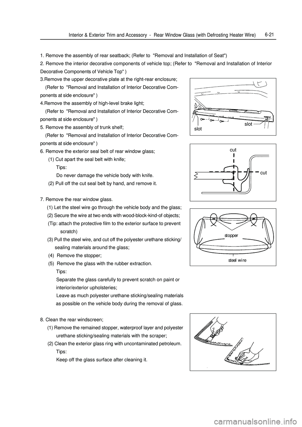
Interior & Exterior Trim and Accessory -Rear Window Glass (with Defrosting Heater Wire)6-211. Remove the assembly of rear seatback; (Refer to "Removal and Installation of Seat")
2. Remove the interior decorative components of vehicle top; (Refer to "Removal and Installation of Interior
Decorative Components of Vehicle Top" )
3.Remove the upper decorative plate at the right-rear enclosure;
(Refer to "Removal and Installation of Interior Decorative Com-
ponents at side enclosure" )
4.Remove the assembly of high-level brake light;
(Refer to "Removal and Installation of Interior Decorative Com-
ponents at side enclosure" )
5. Remove the assembly of trunk shelf;
(Refer to "Removal and Installation of Interior Decorative Com-
ponents at side enclosure" )
6. Remove the exterior seal belt of rear window glass;
(1) Cut apart the seal belt with knife;
Tips:
Do never damage the vehicle body with knife.
(2) Pull off the cut seal belt by hand, and remove it.
7. Remove the rear window glass.
(1) Let the steel wire go through the vehicle body and the glass;
(2) Secure the wire at two ends with wood-block-kind-of objects;
(Tip: attach the protective film to the exterior surface to prevent
scratch)
(3) Pull the steel wire, and cut off the polyester urethane sticking/
sealing materials around the glass;
(4) Remove the stopper;
(5) Remove the glass with the rubber extraction.
Tips:
Separate the glass carefully to prevent scratch on paint or
interior/exterior upholsteries;
Leave as much polyester urethane sticking/sealing materials
as possible on the vehicle body during the removal of glass.
8. Clean the rear windscreen;
(1) Remove the remained stopper, waterproof layer and polyester
urethane sticking/sealing materials with the scraper;
(2) Clean the exterior glass ring with uncontaminated petroleum.
Tips:
Keep off the glass surface after cleaning it.slotslot
cut
cut
stopper
steel wire
Page 352 of 416

Interior & Exterior Trim and Accessory -
Side Inner Panel Trim6-233. To remove the right rear doorsill shield.
Use screwdriver to loosen 6 buckles and detach the right rear
doorsill shield.
Notes:
Wrap the sharp end of screwdriver up with adhesive tape before
operation.
4. Detach the left rear doorsill shield.
5. Detach the right front pillar trim
Use the screwdriver to loosen the clip and detach the right front
pillar lower trim.
Note:
Wrap the sharp end of screwdriver up with adhesive tape before
operation.
6. Detach the left front pillar trim.
7. Detach the right center pillar trim
Use the screwdriver to disconnect 2 clips, 4 buckles and detach
the right mid pillar lower trim.
Notes:
Wrap the sharp end of screwdriver up with adhesive tape before
operation.
8. Detach the left center pillar lower trim.
9. Detach the right center pillar upper trim.
a. Use the screwdriver to open the pulley cover of the seat belt;
b. Unscrew the bolts and detach the belt rings from the car.
c. Use the screwdriver to loosen the clip and detach the right
center pillar upper trim.
Notes:
Wrap the sharp end of screwdriver up with adhesive tape before
operation.
10. Detach the left center pillar upper trim.
11. Detach the backseat cushion assy.
12. Detach the backrest assy.Clasp ClaspClasp
clip
clip
clip
Page 353 of 416

Interior & Exterior Trim and Accessory -Side Inner Panel Trim6-2413. Detach the luggage shelf assy.;
a. Detach the high-mounted stop lamp assy.;
b. Unfix three clips;
c.To pull the belt from the rift and detach the luggage shelf assy;
14. To remove the right quarter upper trim;
Use the screwdriver to unfasten 5 clips and 1 buckle and detach
the right quarter upper trim.
Notes:
Before using the screwdriver, apply the tape to cover its head.
15. Detach the left quarter upper trim.
16. Detach the right quarter lower trim.
a. Unfasten bolts and brackets.
b. Use the screwdriver to unfix 3 clips and detach the right quarter
lower trim.
Notes:
Wrap the sharp end of screwdriver up with adhesive tape before
operation.
17. Detach the left quarter lower trim.
18. Detach the ring front pillar upper trim.
Use the screwdriver to unfix 2 clips and detach the ring front pillar
trim.
Notes:
Wrap the sharp end of screwdriver up with adhesive tape before
operation.
19. Detach the left front pillar upper trim.Clip clip
clip
clipClipcut
Page 360 of 416

6-31II. Removal and Installation of the Rear Door Interior trim Tip:
Installation is basically the reverse of removal and different operation(s) in the process of installation, if any,
will be pointed out specifically.
The removal and installation at the right side are the same as those at the left side.
1. Remove the interior decorative plate handle of left rear door;
Remove a screw with the cross-head screwdriver, and then take
off the interior decorative plate handle of left-rear door.
Tip:
Wrap the head of screwdriver with belt before using it.
2. Remove the assembly of electric-driven window regulator switch;
a. Release the grips with the straight screwdriver, and then re
move the regulator switch off the decorative plate.
b. Disconnect the switch connector.
3. Remove the interior decorative plate of left rear door;
a. Remove the screws and buckles;
b. Release the 6 buckles with the straight screwdriver, and hold
upwards the interior decorative plate of rear-left door to re
move it.
Tip:
Wrap the head of screwdriver with belt before using it.
4. Remove the interior handle of left-rear door;
Release the 2 hooks, remove the interior handle of left-rear door,
and disconnect the 2 wires off the interior handle of left-rear door.
5. Remove off the rain-proof film on the door;clip
HookHookgripsInterior & Exterior Trim and Accessory -Rear Door Interior Trim
Page 376 of 416

(3) Side Wall Assembly The left/right side wall assembly is a frame structure, which is a side component that connects the front and
rear parts of the body. As shown in Fig.5-4, it includes left/right side wall outside plate assembly, left/right wheel
assembly, left/right A post inside plate assembly, and left/right intermediate post interior plate assembly etc.Survey -Body Structure7-4Fig. 5-4 Side Wall Assembly
1. LH/RH upper front body inner pillar 2.LH/RH lower front body inner pillar 3.LH/RH no.1 crossemember joint panel
4.LH/RH roof inner rail 5.LH/RH center body inner pillar 6.LH/RH rear crossmember tee joint panel
7.LH/RH lower rear pillar remforcement panel 8.LH/RH roof rear inner panel 9.LH/RH side rear pillar inner panel
10.LH/RH luggage compartment support panel 11.LH/RH luggage compartment hinge fixing panel
12.LH/RH wheel house outer panel 13.LH/RH wheel house inner panel 14.LH/RH side panel
15.LH/RH rear combination lamp fixing panel 16.Fuel refilling cap assembly 17.LH/RH side doorsill outer reinforcement panel
18.LH/RH side doorsill inner reinforcement panel 19.LH/RH center pillar upper reinforcement panel
20.LH/RH front seat belt upper reinforcement panel 21.LH/RH roof rail upper master reinforcement panel
22.LH/RH center pillar middle reinforcement panel 23.LH/RH center pillar lower reinforcement panel
24.LH/RH roof rail assistant reinforcement panel 25.LH/RH front body pillar upper reinforcement panel
26.LH/RH front body pillar outer reinforcement panel
Page 413 of 416

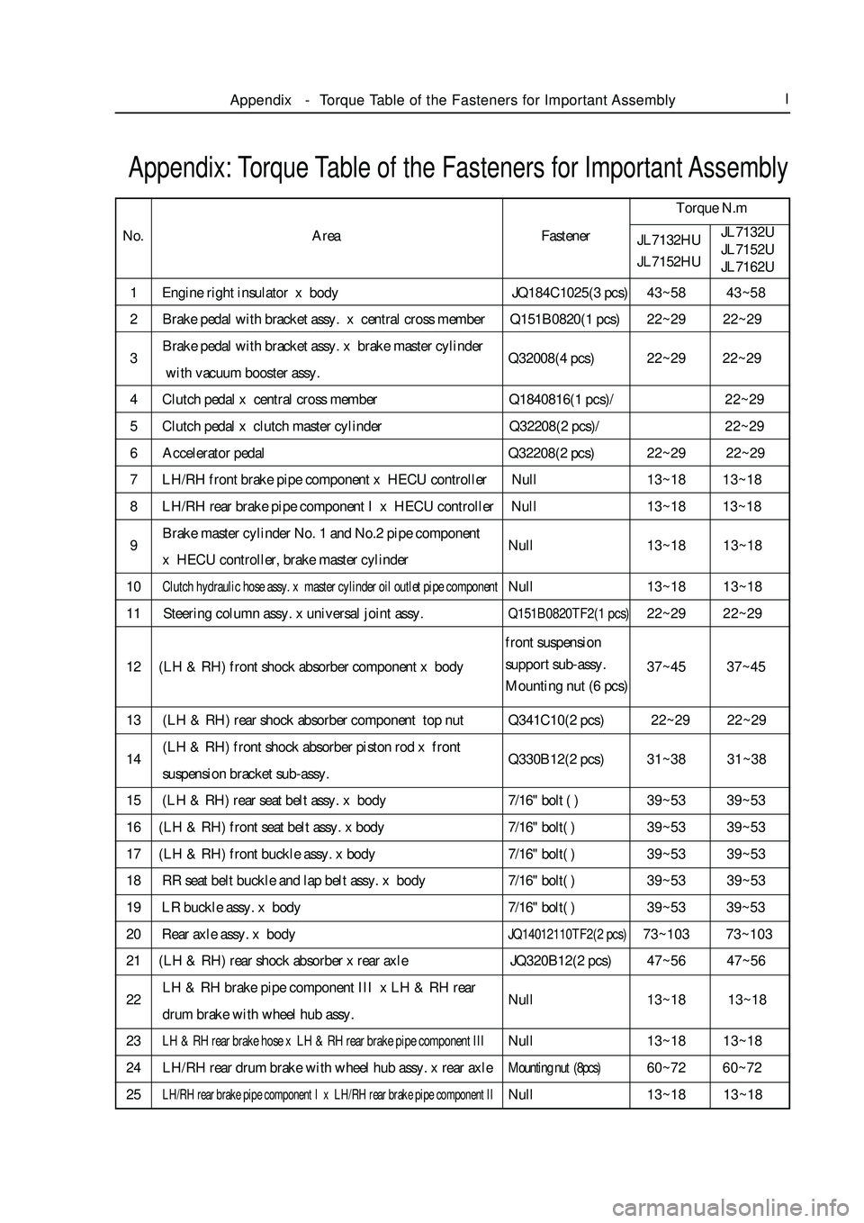
1 Engine right insulator x body JQ184C1025(3 pcs)43~58 43~58
2 Brake pedal with bracket assy. x central cross member Q151B0820(1 pcs)22~29 22~29
3Brake pedal with bracket assy. x brake master cylinder
Q32008(4 pcs)22~29 22~29
with vacuum booster assy.
4 Clutch pedal x central cross member Q1840816(1 pcs)/22~29
5 Clutch pedal x clutch master cylinder Q32208(2 pcs)/22~29
6 Accelerator pedal Q32208(2 pcs)22~29 22~29
7 LH/RH front brake pipe component x HECU controller Null13~18 13~18
8 LH/RH rear brake pipe component I x HECU controller Null13~18 13~18
9Brake master cylinder No. 1 and No.2 pipe component
Null13~18 13~18
x HECU controller, brake master cylinder
10Clutch hydraulic hose assy. x master cylinder oil outlet pipe componentNull13~18 13~18
11 Steering column assy. x universal joint assy.Q151B0820TF2(1 pcs)22~29 22~29
12 (LH & RH) front shock absorber component x body37~45 37~45
13 (LH & RH) rear shock absorber component top nut Q341C10(2 pcs) 22~29 22~29
14(LH & RH) front shock absorber piston rod x front
Q330B12(2 pcs)31~38 31~38
suspension bracket sub-assy.
15 (LH & RH) rear seat belt assy. x body7/16" bolt ( )39~53 39~53
16 (LH & RH) front seat belt assy. x body7/16" bolt( )39~53 39~53
17 (LH & RH) front buckle assy. x body7/16" bolt( )39~53 39~53
18 RR seat belt buckle and lap belt assy. x body7/16" bolt( )39~53 39~53
19 LR buckle assy. x body7/16" bolt( )39~53 39~53
20 Rear axle assy. x bodyJQ14012110TF2(2 pcs)73~103 73~103
21 (LH & RH) rear shock absorber x rear axle JQ320B12(2 pcs)47~56 47~56
22LH & RH brake pipe component III x LH & RH rear
Null13~18 13~18
drum brake with wheel hub assy.
23LH & RH rear brake hose x LH & RH rear brake pipe component IIINull13~18 13~18
24 LH/RH rear drum brake with wheel hub assy. x rear axleMounting nut (8pcs)60~72 60~72
25LH/RH rear brake pipe component I x LH/RH rear brake pipe component IINull13~18 13~18Appendix: Torque Table of the Fasteners for Important AssemblyTorque N.m
No.
JL7132HU
JL7152HUJL7132U
JL7152U
JL7162UAppendix-Torque Table of the Fasteners for Important AssemblyIArea Fastener
front suspension
support sub-assy.
Mounting nut (6 pcs)