check engine light GEELY MK 2008 User Guide
[x] Cancel search | Manufacturer: GEELY, Model Year: 2008, Model line: MK, Model: GEELY MK 2008Pages: 416, PDF Size: 25.19 MB
Page 203 of 416

Suspected area
1. Wiring harness or connector
2. ECM
3. Combination instrument assy.
1. Wiring harness or connector
2. Alternator
3. Combination instrument assy.
1. Wiring harness or connector
2. Manual brake switch
3. Combination instrument assy.
1. Wiring harness or connector
2. Brake fluid level switch
3. Combination instrument assy.
1. Wiring harness or connector
2. ABS ECU or ABS warning lamp driving module
3. Combination instrument assy.
1. Wiring harness or connector
2. Airbag ECU controller
3. Combination instrument assy.
1. Wiring harness or connector
2. Airbag ECU controller
3. Combination instrument assy.
1. Wiring harness or connector
2. Front head light dimmer switch
3. Combination instrument assy.
1. Wiring harness or connector
2. Front head light dimmer switch
3. Combination instrument assy.
1. Wiring harness or connector
2. Rear defrost switch
3. Combination instrument assy. 8. Warning lamp fails
Symptom
Check that engine warning lamp does not
illuminate
Charge warning lamp does not illuminate
Park braking warning lamp does not
illuminate
Brake failure warning lamp does not
illuminate
ABS warning lamp does not illuminate
SRS warning lamp does not illuminate
Passenger's airbag indicator lamp does
not illuminate
High beam indicator lamp does not
illuminate
Rear foglight indicator lamp does not
illuminate
Rear defrost indicator lamp does not
illuminate5-16Combination Instrument System -Malfunction Symptom Table and Troubleshooting
Page 206 of 416

Note:
To measure, disconnect the connector.
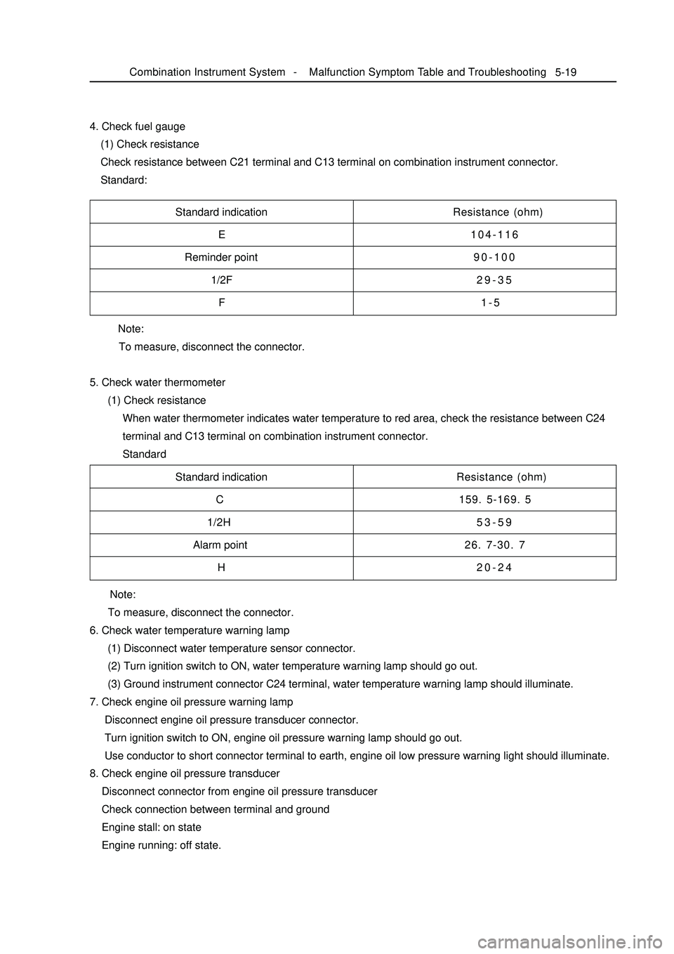
5. Check water thermometer
(1) Check resistance
When water thermometer indicates water temperature to red area, check the resistance between C24
terminal and C13 terminal on combination instrument connector.
Standard 4. Check fuel gauge
(1) Check resistance
Check resistance between C21 terminal and C13 terminal on combination instrument connector.
Standard:5-19Standard indication
E
Reminder point
1/2F
FResistance (ohm)
104-116
90-100
29-35
1-5
Standard indication
C
1/2H
Alarm point
HResistance (ohm)
159. 5-169. 5
53-59
26. 7-30. 7
20-24
Note:
To measure, disconnect the connector.
6. Check water temperature warning lamp
(1) Disconnect water temperature sensor connector.
(2) Turn ignition switch to ON, water temperature warning lamp should go out.
(3) Ground instrument connector C24 terminal, water temperature warning lamp should illuminate.
7. Check engine oil pressure warning lamp
Disconnect engine oil pressure transducer connector.
Turn ignition switch to ON, engine oil pressure warning lamp should go out.
Use conductor to short connector terminal to earth, engine oil low pressure warning light should illuminate.
8. Check engine oil pressure transducer
Disconnect connector from engine oil pressure transducer
Check connection between terminal and ground
Engine stall: on state
Engine running: off state.Combination Instrument System -Malfunction Symptom Table and Troubleshooting
Page 207 of 416

5-209. Check park warning lamp
(1) Disconnect connector from park switch
(2) Turn ignition switch to ON, park brake warning lamp should go out.
(3) Use conductor to short connector terminal to ground, park brake warning lamp should illuminate.
10. Check park switch
(1) Disconnect connector from park switch
(2) Pull up manual brake, check whether its terminal is connected with ground
Pull up manual brake: on
Manual brake release: off
11. Brake fluid level warning lamp
(1) Disconnect connector from brake fluid level sensor
(2) Turn ignition switch to ON, brake fluid level warning lamp should go out.
(3) Use conductor to connect its connector terminal wiring harness terminals directly, brake fluid level
warning lamp should illuminate.
12. Check brake fluid level warning switch
(1) Remove tank cap
(2) Disconnect connector from tank
(3) Check whether terminals are connected.
Floater on top: off
(4) Use sucker to suck out liquid from tank
(5) Check whether terminals are connected.
Floater down: on state
(6) Pour liquid back into tank
13. Rear defrost indicator lamp
(1) Turn ignition switch to ON, and start up engine
(2) Push down defrost switch, now rear defrost indicator lamp should illuminate
(3) Turn ignition switch to OFF, rear defrost indicator lamp should go out
14. Rear foglight indicator lamp
When rear foglight illuminates, rear foglight indicator lamp should illuminate, now A5 terminal should be high
potential.
15. Safety belt warning indicator lamp
(1) Disconnect safety belt switch connector from driver side, now safety belt warning indicator lamp should
go out.
(2) Short connector terminal to ground, safety belt warning indicator lamp should illuminate.Combination Instrument System -Malfunction Symptom Table and Troubleshooting
Page 288 of 416

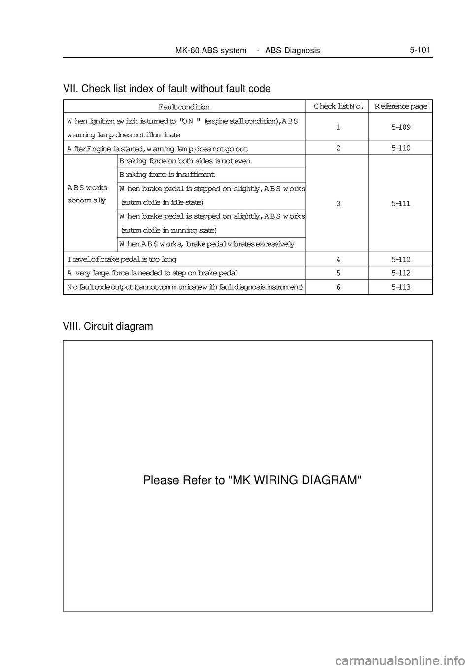
VIII. Circuit diagramVII. Check list index of fault without fault codeMK-60 ABS system -ABS Diagnosis5-101Fault condition
When Ignition switch is turned to "ON " (engine stall condition), ABS
warning lamp does not illuminate
After Engine is started, warning lamp does not go outCheck list No.
1
2
3
4
5
6Reference page
5-109
5-110
5-111
5-112
5-112
5-113 ABS works
abnormallyBraking force on both sides is not even
Braking force is insufficient
When brake pedal is stepped on slightly, ABS works
(automobile in idle state)
When brake pedal is stepped on slightly, ABS works
(automobile in running state)
When ABS works, brake pedal vibrates excessively
Travel of brake pedal is too long
A very large force is needed to step on brake pedal
No fault code output (cannot communicate with fault diagnosis instrument)Please Refer to "MK WIRING DIAGRAM"