oil temperature GEELY MK 2008 User Guide
[x] Cancel search | Manufacturer: GEELY, Model Year: 2008, Model line: MK, Model: GEELY MK 2008Pages: 416, PDF Size: 25.19 MB
Page 42 of 416
Part III EngineChpater 1 Engine AssemblyInformation about engine accessories in MK-1 Car Maintenance Manual deals with only that concerned with a
complete car. Please refer to separated Maintenance Manual for information about the engine body. Engines
concerned are MR479Q, MR479QA and MR481QA.Section 1 Engine Inspection1. Check the engine oil
(1) Check the oil level.
(2) Start the engine, and reach warm-up temperature.
(3) Shut the engine down, wait for 3-5min, and check the oil level.
(4) Check whether the oil level is in within the range marked by the scale; if it is lower than the limit (mark
L), fill oil to mark F.
(5) Keep the oil clean without any coolant or petrol mixed in and with appropriate viscosity.
2. Change oil.
(1) Start the engine. When normal temperature is reached, shut down the engine.
(2) Open the oil cap, remove the oil drain plug, and drain the oil.
(3) Tighten the oil drain plug to a specified torque 54N.m.
(4) Fill fresh oil into the crank case with oil quantity 2.8L in case of the filter not changed, 3.0L in case of the
filter changed and 3.5L in case of the dry filter.
(5) Fit on the oil filling cap.
(6) Start the engine.
(7) Shut down the engine and check the oil quantity, and fill oil to the mark F on the oil scale if necessary.
3. Replace the oil filter.
(1) Remove the oil filter.
(2) Before mounting the oil filter, apply a small quantity of engine oil to the O-ring of the new oil filter.
(3) Tight the oil filter to a specified torque (12.7N.m).
(4) Start the engine, and check whether there is any leakage
(5) Shut down the engine, check the oil quantity and fill as required.
4. Oil selection
Oil over PAI SG grade is preferred.
SAE10W-30 or SAE10W-40 is preferred, and ASE5W-30 is used in cold region in the winter.
Note: For the best effect and the greatest safety, it is advisable to use the following lubrication oil.
a. Meet the requirements of API level.
b. Select proper SAE viscosity rating within expected ambient temperature.
The lubrication oil that can not meet the requirements of SAE viscosity and API label at the same time is not
allowed.
5. Check the coolant.
(1) After the engine is cooled down, remove the radiator cover.EngineEngine Assembly3-1 -
Page 46 of 416

Table 3Section 2 Removal of the Engine Assembly from the Vehicle1. Avoid petrol overflowing (Disconnect from the fuel tank).
2. Remove the front wheel.Figure 1-5Engine AssemblyRemoval of the Engine Assembly from the Vehicle3-5CO
Normal
Low
HighHC
High
High
HighProblems
Bad idle speed
Bad idle speed
(HC reading fluctuates)
Bad idle speed
(Black smoke exhausts)Causes
1. Ignition fault:
Incorrect ignition timing;
Dirt, short circuit, or incorrect spark plug gap.
2. Incorrect valve gap.
3. Suction and exhaust valve leak.
4. Cylinder leaks.
1. Vacuum leaks.
PCV pipe . manifold;
Idle speed control valve;
Brake booster pipeline.
2. Spark lacks since the mixed gas is too thin.
1. Air filter is blocked.
2. PCV valve is blocked.
3. EFI system fails.
ECU fails.
Pressure regulator of fuel oil is out of order.
Water temperature sensor does not work.
Suction pressure/temperature sensor fails.
Injector fails.
The throttle position sensor fails.3. Discharge the coolant completely.
4. Remove the air filter assembly with hose (see Figure 1-5).
(1) Disconnect the joint of the temperature sensor and the wire
plug.
(2) Disconnect the vent duct from the hose of the air filter.
(3) Release the wire clip bolt on the air filter.
(4) Disconnect the hose of the air filter from the throttle body.
(5) Remove 3 bolts and the air filter assemblies.
5. Remove the battery.
6. Remove the fuel pipe sub-assembly.
7. Disconnect the water pipe; disconnect the water outlet pipe of the
heater from the air conditioner pipe.
8. Release the nut and remove the accelerator control cable. -
Page 51 of 416
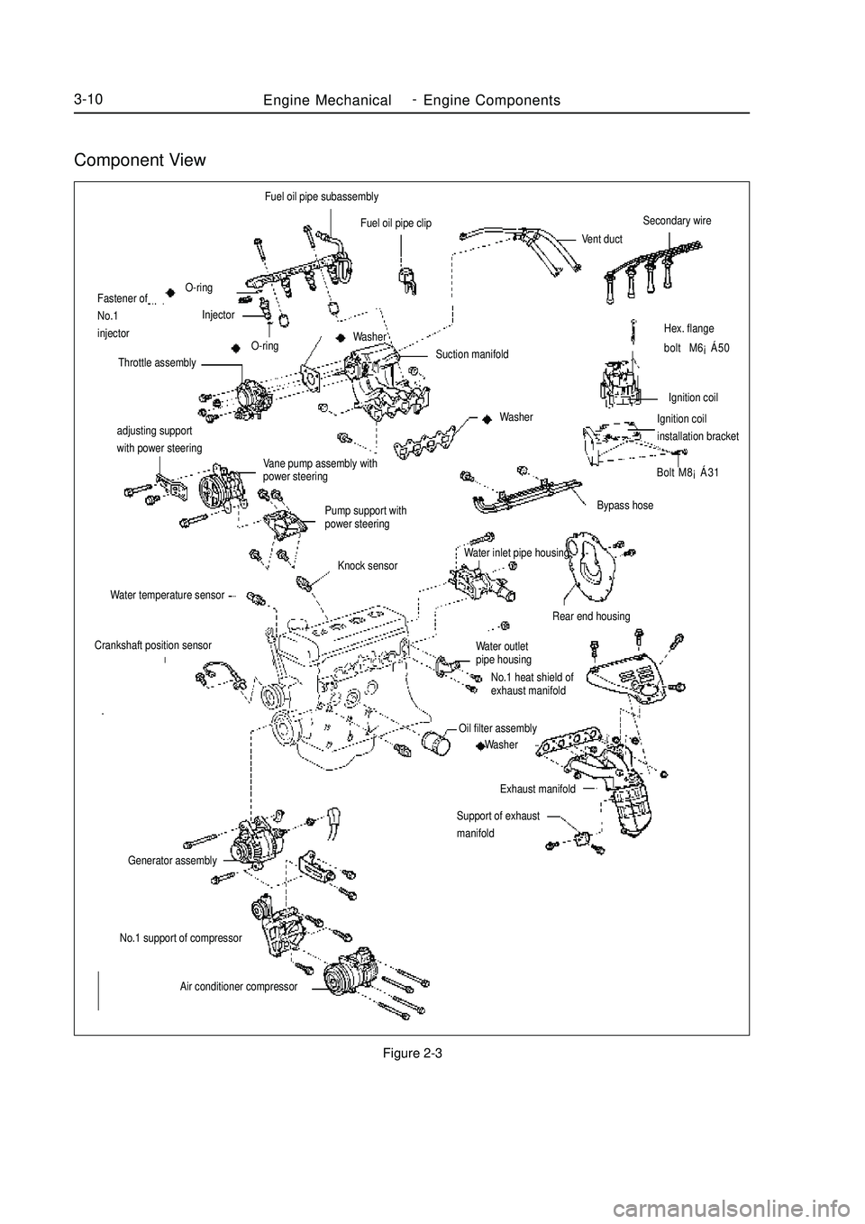
Component ViewFigure 2-3Engine MechanicalEngine Components3-10adjusting support
with power steering
Vane pump assembly with
power steering
Pump support with
power steeringHex. flange
bolt M6¡Á50
Ignition coil
Ignition coilinstallation bracket
Bolt M8¡Á31Fuel oil pipe subassembly
Fuel oil pipe clip
Vent ductSecondary wireBypass hose
Rear end housingWater outlet
pipe housing
No.1 heat shield of
exhaust manifoldOil filter assembly
Washer
Exhaust manifold
Support of exhaust
manifoldO-ring
Fastener of
No.1
injectorInjector
O-ring
Throttle assemblySuction manifold Washer
WasherKnock sensor
Water temperature sensorCrankshaft position sensorGenerator assemblyNo.1 support of compressor
Air conditioner compressorWater inlet pipe housing -
Page 63 of 416
2. Check the engine coolant quantity in the compensating tank.
The coolant level should be between LOW and FULL.
3. Check the coolant quality.
(1) Remove the radiator cover.
Do not remove the radiator cover when the engine and the radiator are still hot in order to avoid scalding
since the liquid vapor may inject.
(2) Check whether there are excessive deposit and rust or sundries around the radiator cover. The coolant is
not allowed to contact with oil.
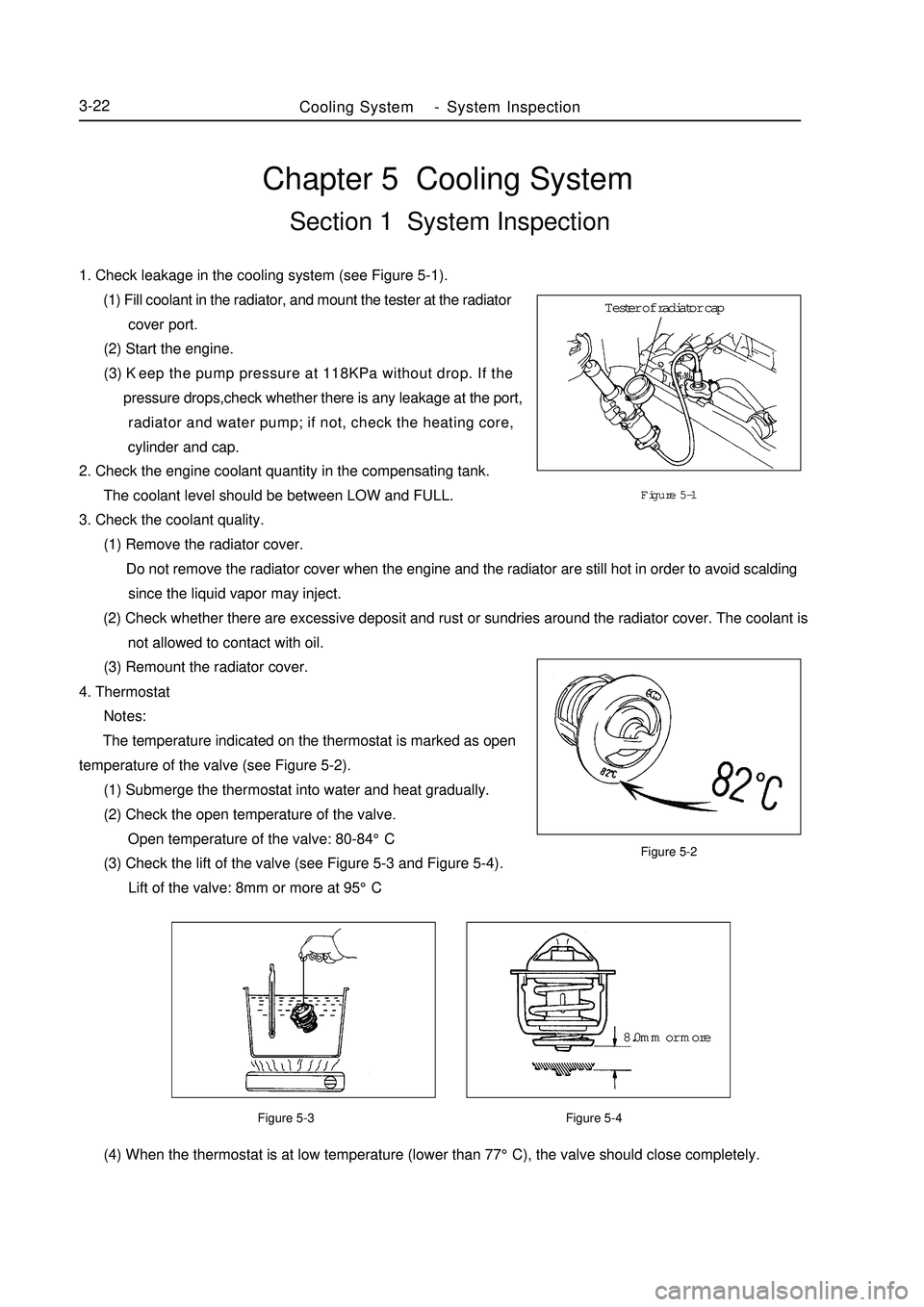
(3) Remount the radiator cover.Chapter 5 Cooling SystemSection 1 System Inspection1. Check leakage in the cooling system (see Figure 5-1).
(1) Fill coolant in the radiator, and mount the tester at the radiator
cover port.
(2) Start the engine.
(3) Keep the pump pressure at 118KPa without drop. If the
pressure drops,check whether there is any leakage at the port,
radiator and water pump; if not, check the heating core,
cylinder and cap.Figure 5-1
Figure 5-2
Figure 5-3 Figure 5-4 (4) When the thermostat is at low temperature (lower than 77°C), the valve should close completely.Cooling SystemSystem Inspection3-224. Thermostat
Notes:
The temperature indicated on the thermostat is marked as open
temperature of the valve (see Figure 5-2).
(1) Submerge the thermostat into water and heat gradually.
(2) Check the open temperature of the valve.
Open temperature of the valve: 80-84°C
(3) Check the lift of the valve (see Figure 5-3 and Figure 5-4).
Lift of the valve: 8mm or more at 95°CTester of radiator cap
8.0mm or more -
Page 73 of 416
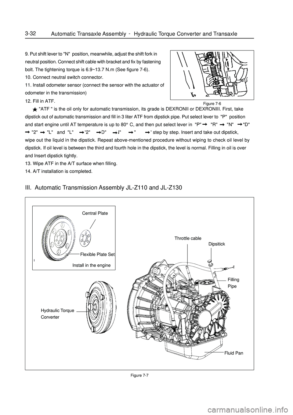
9. Put shift lever to "N" position, meanwhile, adjust the shift fork in
neutral position. Connect shift cable with bracket and fix by fastening
bolt. The tightening torque is 6.9~13.7 N.m (See figure 7-6).
10. Connect neutral switch connector.
11. Install odometer sensor (connect the sensor with the actuator of
odometer in the transmission)Figure 7-712. Fill in ATF.
"ATF " is the oil only for automatic transmission, its grade is DEXRONII or DEXRONIII. First, take
dipstick out of automatic transmission and fill in 3 liter ATF from dipstick pipe. Put select lever to "P" position
and start engine until AT temperature is up to 80°C, and then put select lever in "P" "R" "N" "D"
"2" "L" and "L" "2" "D" "N" "R" "P" step by step. Insert and take out dipstick,
wipe out the liquid in the dipstick. Repeat above-mentioned procedure without wiping to check oil level by
dipstick. If oil level is between the third and fourth hole in the dipstick, the level is normal. Filling in oil is over
and Insert dipstick tightly.
13. Wipe ATF in the A/T surface when filling.
14. A/T installation is completed.3-32Install in the engineCentral PlateFlexible Plate SetThrottle cableDipsitickFilling
PipeFluid Pan Hydraulic Torque
CorverterIII. Automatic Transmission Assembly JL-Z110 and JL-Z130Figure 7-6Automatic Transaxle Assembly Hydraulic Torque Converter and Transaxle -
Page 196 of 416
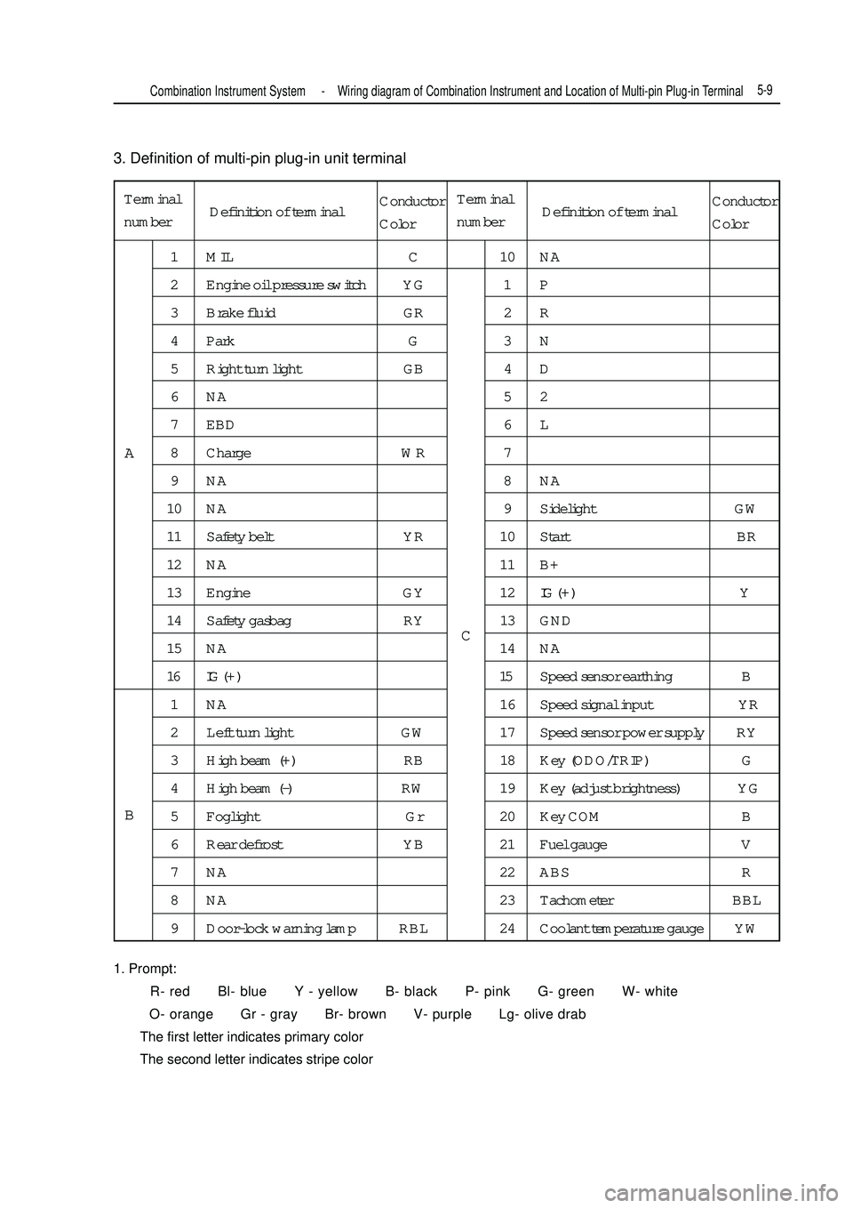
3. Definition of multi-pin plug-in unit terminal
1. Prompt:
R- red Bl- blue Y - yellow B- black P- pink G- green W- white
O- orange Gr - gray Br- brown V- purple Lg- olive drab
The first letter indicates primary color
The second letter indicates stripe colorTerminal
number1 MIL C 10 NA
2 Engine oil pressure switch YG 1 P
3 Brake fluid GR 2 R
4 Park G 3 N
5 Right turn light GB 4 D
6NA 52
7 EBD 6 L
8 Charge WR 7
9NA 8NA
10 NA 9 Sidelight GW
11 Safety belt YR 10 Start BR
12 NA 11 B+
13 Engine GY 12IG ( + ) Y
14 Safety gasbag RY 13 GND
15 NA 14 NA
16 IG ( + ) 15Speed sensor earthing B
1 NA 16 Speed signal input YR
2 Left turn light GW 17 Speed sensor power supply RY
3 High beam (+) RB 18 Key (ODO/TRIP) G
4 High beam (-) RW 19 Key (adjust brightness) YG
5 Foglight Gr 20 Key COM B
6 Rear defrost YB 21 Fuel gauge V
7 NA 22 ABS R
8 NA 23 Tachometer BBL
9 Door-lock warning lamp RBL 24 Coolant temperature gauge YWA
BCCombination Instrument System -Wiring diagram of Combination Instrument and Location of Multi-pin Plug-in Terminal5-9Definition of terminalConductor
ColorTerminal
numberDefinition of terminalConductor
Color
Page 206 of 416
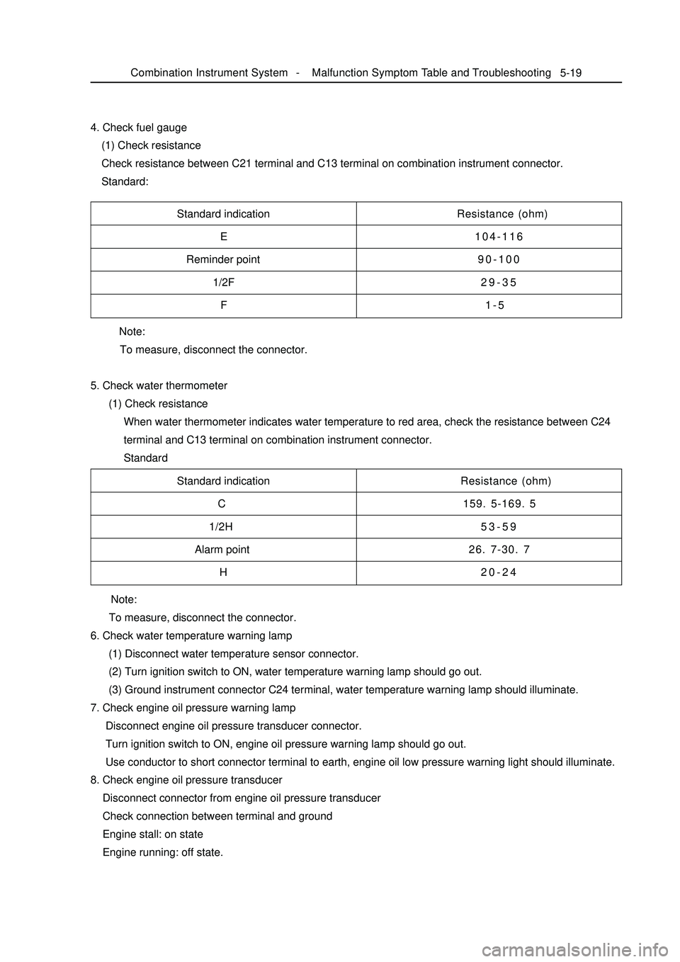
Note:
To measure, disconnect the connector.
5. Check water thermometer
(1) Check resistance
When water thermometer indicates water temperature to red area, check the resistance between C24
terminal and C13 terminal on combination instrument connector.
Standard 4. Check fuel gauge
(1) Check resistance
Check resistance between C21 terminal and C13 terminal on combination instrument connector.
Standard:5-19Standard indication
E
Reminder point
1/2F
FResistance (ohm)
104-116
90-100
29-35
1-5
Standard indication
C
1/2H
Alarm point
HResistance (ohm)
159. 5-169. 5
53-59
26. 7-30. 7
20-24
Note:
To measure, disconnect the connector.
6. Check water temperature warning lamp
(1) Disconnect water temperature sensor connector.
(2) Turn ignition switch to ON, water temperature warning lamp should go out.
(3) Ground instrument connector C24 terminal, water temperature warning lamp should illuminate.
7. Check engine oil pressure warning lamp
Disconnect engine oil pressure transducer connector.
Turn ignition switch to ON, engine oil pressure warning lamp should go out.
Use conductor to short connector terminal to earth, engine oil low pressure warning light should illuminate.
8. Check engine oil pressure transducer
Disconnect connector from engine oil pressure transducer
Check connection between terminal and ground
Engine stall: on state
Engine running: off state.Combination Instrument System -Malfunction Symptom Table and Troubleshooting
Page 250 of 416
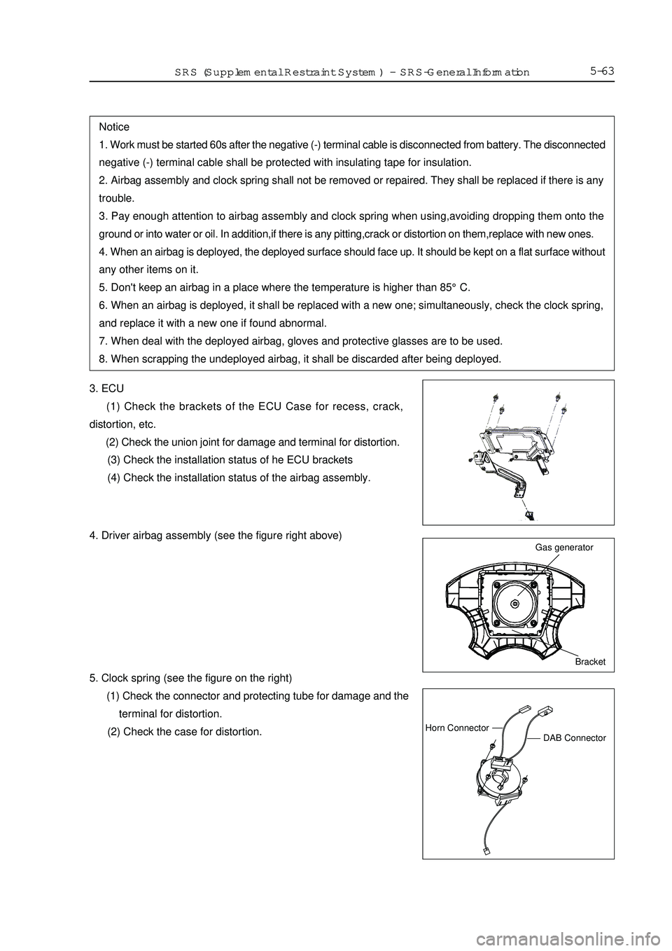
5-633. ECU
(1) Check the brackets of the ECU Case for recess, crack,
distortion, etc.
(2) Check the union joint for damage and terminal for distortion.
(3) Check the installation status of he ECU brackets
(4) Check the installation status of the airbag assembly.Notice
1. Work must be started 60s after the negative (-) terminal cable is disconnected from battery. The disconnected
negative (-) terminal cable shall be protected with insulating tape for insulation.
2. Airbag assembly and clock spring shall not be removed or repaired. They shall be replaced if there is any
trouble.
3. Pay enough attention to airbag assembly and clock spring when using,avoiding dropping them onto the
ground or into water or oil. In addition,if there is any pitting,crack or distortion on them,replace with new ones.
4. When an airbag is deployed, the deployed surface should face up. It should be kept on a flat surface without
any other items on it.
5. Don't keep an airbag in a place where the temperature is higher than 85°C.
6. When an airbag is deployed, it shall be replaced with a new one; simultaneously, check the clock spring,
and replace it with a new one if found abnormal.
7. When deal with the deployed airbag, gloves and protective glasses are to be used.
8. When scrapping the undeployed airbag, it shall be discarded after being deployed.Bracket Gas generatorDAB ConnectorHorn ConnectorSRS (Supplemental Restraint System)-SRS-General Information4. Driver airbag assembly (see the figure right above)
5. Clock spring (see the figure on the right)
(1) Check the connector and protecting tube for damage and the
terminal for distortion.
(2) Check the case for distortion.
Page 259 of 416
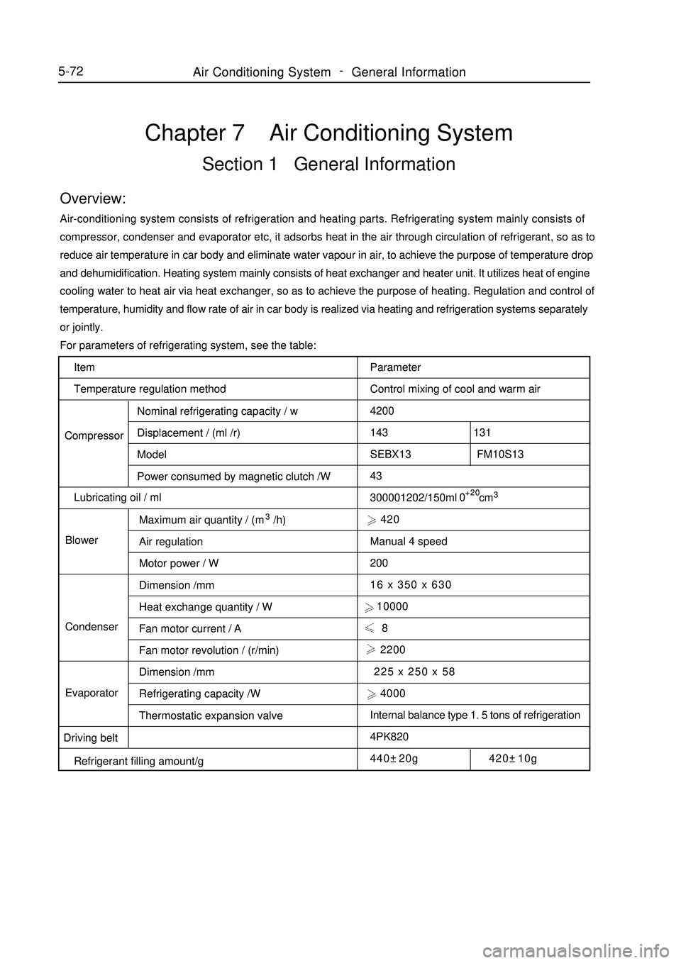
Item
Temperature regulation method
CompressorNominal refrigerating capacity / w
Displacement / (ml /r)
Model
Power consumed by magnetic clutch /W
Lubricating oil / ml
BlowerMaximum air quantity / (m3/h)
Air regulation
Motor power / W
Dimension /mm
Heat exchange quantity / W
Fan motor current / A
Fan motor revolution / (r/min)
Dimension /mm
Refrigerating capacity /W
Thermostatic expansion valve Condenser
Evaporator
Driving belt
Refrigerant filling amount/gChapter 7 Air Conditioning SystemSection 1 General InformationOverview:Air-conditioning system consists of refrigeration and heating parts. Refrigerating system mainly consists of
compressor, condenser and evaporator etc, it adsorbs heat in the air through circulation of refrigerant, so as to
reduce air temperature in car body and eliminate water vapour in air, to achieve the purpose of temperature drop
and dehumidification. Heating system mainly consists of heat exchanger and heater unit. It utilizes heat of engine
cooling water to heat air via heat exchanger, so as to achieve the purpose of heating. Regulation and control of
temperature, humidity and flow rate of air in car body is realized via heating and refrigeration systems separately
or jointly.
For parameters of refrigerating system, see the table:
Parameter
Control mixing of cool and warm air
4200
143 131
SEBX13 FM10S13
43
300001202/150ml cm3 420
Manual 4 speed
200
16 x 350 x 630
10000
8
2200
225 x 250 x 58
4000
Internal balance type 1. 5 tons of refrigeration
4PK820
440±20g 420±10g+20
05-72Air Conditioning System -
General Information
Page 307 of 416
Fault symptom
Flameout, poor idle speedChapter 9 Engine EFI SystemI. Outline This system includes sensor that detects engine functioning. Engine ECU utilizes sensors installed at differ-
ent parts of engine to measure various working parameters of engine, accurately control oil injection quantity
according to control procedure set in engine electronic control unit, so engine could work in optimum mode
under various operating conditions, i. e. optimal power output, the most economical oil consumption, optimal
exhaust emissions. Engine ECU is capable of start up control, idle speed closed-loop control, air fuel ratio
closed-loop control, canister control, transient operation control, angle of ignition control, knocking control, air
conditioning control, coasting fuel cutoff and overspeed fuel cutoff control, ternary catalyst heating and protec-
tion control, system self-diagnosis etc.II. Inspection of control element1. Manifold intake pressure temperature sensor
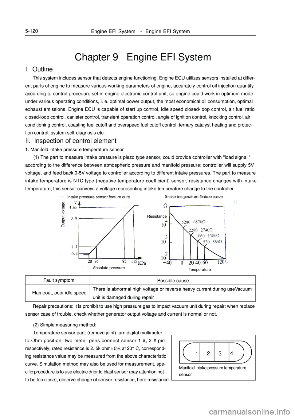
(1) The part to measure intake pressure is piezo type sensor, could provide controller with "load signal "
according to the difference between atmospheric pressure and manifold pressure; controller will supply 5V
voltage, and feed back 0-5V voltage to controller according to different intake pressures. The part to measure
intake temperature is NTC type (negative temperature coefficient) sensor, resistance changes with intake
temperature, this sensor conveys a voltage representing intake temperature change to the controller.
(2) Simple measuring method:
Temperature sensor part: (remove joint) turn digital multimeter
to Ohm position, two meter pens connect sensor 1 #, 2 # pinrespectively, rated resistance is 2. 5k ohm±5% at 20°C, correspond-ing resistance value may be measured from the above characteristic
curve. Simulation method may also be used for measurement, spe-
cific procedure is to use electric drier to blast sensor (pay attention not
to be too close), observe change of sensor resistance, here resistanceEngine EFI System-Engine EFI System5-120Possible cause
There is abnormal high voltage or reverse heavy current during useVacuum
unit is damaged during repair
Repair precautions: it is prohibit to use high pressure gas to impact vacuum unit during repair; when replace
sensor case of trouble, check whether generator output voltage and current is normal or not.1 2 3 4Manifold intake pressure temperature
sensor Intake pressure sensor feature cureIntake temperature feature curve
Output voltageAbsolute pressureTemperatureResistance