torque GEELY MK 2008 Workshop Manual
[x] Cancel search | Manufacturer: GEELY, Model Year: 2008, Model line: MK, Model: GEELY MK 2008Pages: 416, PDF Size: 25.19 MB
Page 3 of 416
Geely “MK” series sedans (JL7132U,JL7132HU,JL7152U,JL7152HU,JL7162U) are brand
new superior models developed by Geely Group who has fully proprietary intellectual property
rights. As a result of the three years of involvements and efforts of the experts from Geely Automo-
bile Research Institute, these sedans reach international leading level in model design, power,
sense of comfort, safety and manufacturing technology while featured in beautiful appearance,
economy, environment protection and safety. The meaning of MK implied that Geely Automobile
has a great development from caterpillar to butterfly. With respect to the power, Geely “MK” series
sedans are equipped with 1.3L, 1.5L, and 1.6L EFI engines developed and manufactured by Geely
itself, and has reached “Chinese III” (Euro III) emission standard.
This manual contains a detailed description of the structures and principles, servicing and adjustment,
removal, assembling technology and matching clearance of the parts of the Geely “MK” sedans
with torque information of the bolts and nuts as well as schematic diagram for special tool operation.
This manual also introduces the transmission control system of the automatic transmission models,
vehicle electric circuits and elaborates ABS system, SRS, BOSCH M7.9.7 electronic control fuel
injection and ignition system, rear parking radar, sound, air conditioning and onboard hands-free
phone system. You can refer to this manual for the information about the regular maintenance,
servicing, adjustment, troubleshooting, removal and installation procedure, specific operations of
the “MK” sedans.
This manual covers the matching relation among the engine assembly, transmission assembly and
the vehicle, but does not have the further description of the structures and principles of the engine
and transmission assemblies and their servicing process. You can refer to the service manuals
solely prepared for engine assembly and transmission assembly for these information.
All information in this manual is based on the latest products released at the time of publication of
this manual. However, the specifications and procedures may need to be modified, and the subse-
quent change will be revealed in later versions.
This manual is prepared by Geely Automobile Research Institute under the assistance of technical
staff from Zhejiang Geely Automobile Co., Ltd and Geely International Corporation. Readers
discovering during the use of this manual the errors and careless omissions due to limited skills of
the preparers and tight schedule are encouraged and pled to contact Geely International in time for
our timely correction of the mistakes.ForewordGeely International Corporation
Nov . 2007
Page 5 of 416
Table of Contents II Section 4 Fuel Emission Control System ....................................................................... 3-18
Section 5 Carbon Canister Replacement ....................................................................... 3-19
Chapter 4 Exhaust System................................................................................................. 3-21
Chapter 5 Cooling System................................................................................................. 3-22
Section 1 System Inspection .......................................................................................... 3-22
Section 2 Radiator Replacement ................................................................................... 3-24
Chapter 6 Manual Transaxle Assembly............................................................................. 3-25
Section 1 Frequent Problem Diagnosis .......................................................................... 3-25
Section 2 Vehicle Speed Sensor Replacement ............................................................. 3-26
Section 3 Manual Transaxle Replacement ..................................................................... 3-27
Section 4 Transmission/Transaxle Case Oil Seal Replacement .................................... 3-28
Chapter 7 Automatic Transaxle Assembly........................................................................ 3-29
Section 1 Frequent Problems Diagnosis ........................................................................ 3-29
Section 2 Hydraulic Torque Converter and Transaxle .................................................... 3-30
Section 3 Differential Front Oil Seal (ATM) .................................................................... 3-33
Section 4 Neutral Switch Assembly ................................................................................ 3-35Part IV ChassisChapter 1 Transmission Control........................................................................................ 4-1
Section 1 Introduction of Transmission Control ............................................................. 4-1
Section 2 Cable Type Transmission Control .................................................................. 4-3
Section 3 Manual Transmission Shift Mechanism .......................................................... 4-5
Section 4 Automatic Transmission Shift Mechanism ...................................................... 4-7
Chapter 2 Accelerator Pedal Device................................................................................. 4-11
Section 1 Introduction of Accelerator Pedal ................................................................... 4-11
Chapter 3 Clutch Control System...................................................................................... 4-12
Section 1 Introduction of Clutch Centrol ......................................................................... 4-12
Section 2 Clutch Pedal ...................................................................................................4-13
Chapter 4 Propeller Shaft/Driveshaft................................................................................ 4-17
Section 1 Propeller Shaft, Driveshaft and Transaxle ..................................................... 4-17
Page 9 of 416
Chapter 14 Outside Rearview Mirror................................................................................. 6-37
Chapter 15 Door Protecting Stripe.................................................................................... 6-38
Chapter 16 Carpet and Insulator....................................................................................... 6-39
Chapter 17 Moonroof Assembly (Optional)...................................................................... 6-40
Chapter 18 Plug List........................................................................................................... 6-42Part 7 BodyChapter 1 Survey................................................................................................................ 7-1
Section 1 Body Structure ................................................................................................ 7-1
Chapter 2 Body Repair....................................................................................................... 7-9
Section 1 Body Damage Forms and Requirements for Repair ...................................... 7-9
Section 2 Typical Technique of Body Panel Repair ....................................................... 7-16
Section 3 Repair After Body Damage ............................................................................ 7-16
Section 4 Features and Composition of Automobile Body ............................................ 7-24
Section 5 Painting Techniques After Body Repair ......................................................... 7-35
Section 6 Service Data For for Body .............................................................................. 7-36Attachment: Body Key Dimensions
Appendix: Torque Table of the Fasteners for Important AssemblyTable of Contents VI
Page 10 of 416
General Information - How to Use This Manual1-1Part 1 General InformationChapter 1 How to Use This ManualI. Instruction1. General Information
(1)This manual conform to the first part of GB/T1.1--2000 Standardization Guide: The structure and prepar-
ing rule of the standard.
(2)Generally, the repairing job can be divided into the following 3 procedures:
1. Diagnosis
2. Removal and installation, replacement, disassembly and inspection, adjustment
3. Final inspection
(3) The first procedure “Diagnosis” (the details refers to each section or chapter) and second procedure “Re-
moval and installation, replacement, disassembly and inspection, adjustment” are scattered in the chapters and
sections, and this manual omits the third procedure “Final inspection”.
(4) This manual does not include the following basic operations which are imperative in real scenarios.
operate the jack or lifter
b. clean the removed parts if necessary.
c. inspect the appearance
2. Preparation
SST (Special Service Tools) and SSM (Special Service Materials) may be required and correctly used based
on the repairing condition, make sure the job procedure is followed.
3. Repair Procedure
(1) The disassembly illustration is placed under the title.
(2) The illustration shows the disassembly of the parts to help you understand the assembly of the parts. (3) Non-reusable parts need to be coated with grease, and the precoated parts and torque are specially shownin the disassembly illustration.
(4) Sometimes, the illustrations of the similar model are used where there may be some details differently
from the actual vehicle.
(5)The operational procedure is described in the following ways:
a. The illustration shows what to do and where to do it.
b. The task heading tells what to do.
c.The detailed text tells how to perform the task and gives other information such as specifications and
warnings.
4. Specification
Specifications are presented in bold type throughout the manual.
5.Term Definition
6. International System of Unit
The Units given in this manual are primarily expressed according to the International System of Unit.Caution indicates there is a possibility of injury to you or other people.
Notice indicates the possibility of damage to the components being repaired.
Tip provides additional information to help you perform the repair efficiently.a.
Page 13 of 416
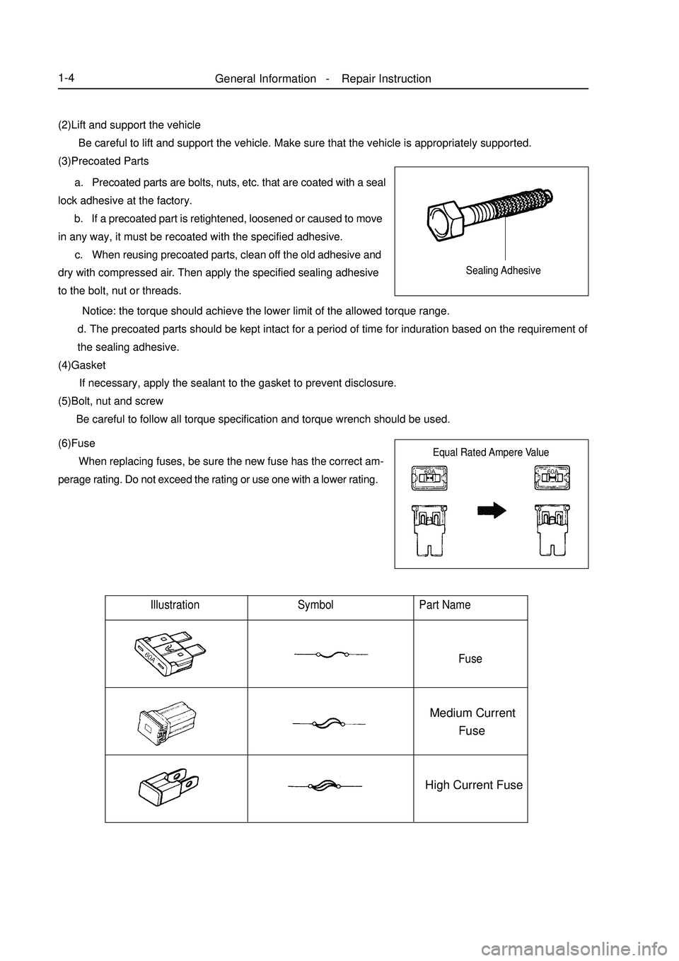
General Information - Repair Instruction1-4(2)Lift and support the vehicle
Be careful to lift and support the vehicle. Make sure that the vehicle is appropriately supported.
(3)Precoated Parts a. Precoated parts are bolts, nuts, etc. that are coated with a seal
lock adhesive at the factory. b. If a precoated part is retightened, loosened or caused to move
in any way, it must be recoated with the specified adhesive. c. When reusing precoated parts, clean off the old adhesive and
dry with compressed air. Then apply the specified sealing adhesive
to the bolt, nut or threads.Illustration Symbol Part Name
FuseMedium Current
Fuse
High Current Fuse Notice: the torque should achieve the lower limit of the allowed torque range.
d.The precoated parts should be kept intact for a period of time for induration based on the requirement of
the sealing adhesive.
(4)Gasket
If necessary, apply the sealant to the gasket to prevent disclosure.
(5)Bolt, nut and screw
Be careful to follow all torque specification and torque wrench should be used.
(6)Fuse
When replacing fuses, be sure the new fuse has the correct am-
perage rating. Do not exceed the rating or use one with a lower rating.Sealing Adhesive
Equal Rated Ampere Value
Page 23 of 416
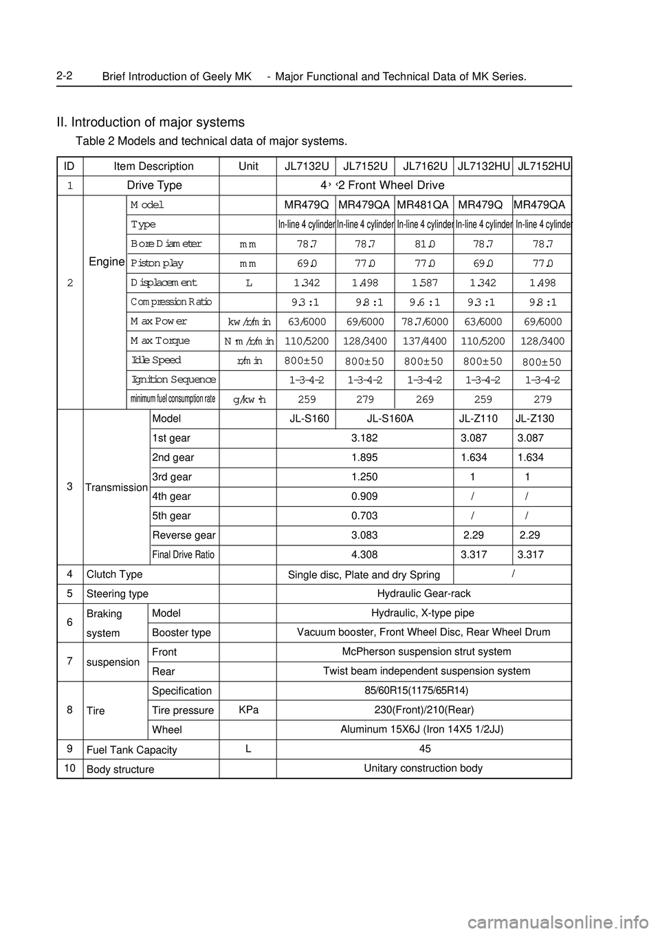
II. Introduction of major systems Table 2 Models and technical data of major systems.
JL7132U JL7152U JL7162U JL7132HU JL7152HU
4
MR479Q MR479QA MR481QA MR479Q MR479QAIn-line 4 cylinder In-line 4 cylinder In-line 4 cylinder In-line 4 cylinder In-line 4 cylinder78.7 78.7 81.0 78.7 78.7
69.0 77.0 77.0 69.0 77.0
1.342 1.498 1.587 1.342 1.498
9.3 : 1 9.8 : 19.6 : 19.3 : 1 9.8 : 1
63/6000 69/6000 78.7/6000 63/6000 69/6000
110/5200 128/3400 137/4400 110/5200 128/3400
800±50
1-3-4-2 1-3-4-2 1-3-4-2 1-3-4-2 1-3-4-2
259 279 269 259 279
JL-S160 JL-S160A JL-Z110 JL-Z130
3.182 3.087 3.087
1.895 1.634 1.634
1.250 1 1
0.909 / /
0.703 / /
3.083 2.29 2.29
4.308 3.317 3.317
Hydraulic Gear-rack
Hydraulic, X-type pipe
Vacuum booster, Front Wheel Disc, Rear Wheel Drum
McPherson suspension strut system
Twist beam independent suspension system
85/60R15(1175/65R14)
230(Front)/210(Rear)
Aluminum 15X6J (Iron 14X5 1/2JJ)
45
Unitary construction body Unit
mm
mm
L
kw/r/min
N.
m/r/min
r/min
g/kw.
h
KPa
L Item Description
Drive Type ID
1
2
3
4
5
6
7
8
9
10EngineModel
Type
Bore Diameter
Piston play
DisplacementCompression RatioMax Power
Max Torque
Idle Speed
Ignition Sequenceminimum fuel consumption rateTransmission
Braking
system
suspension
Tire Clutch Type
Steering type
Model
Booster type
Front
Rear
Specification
Tire pressure
Wheel
Fuel Tank Capacity
Body structureSingle disc, Plate and dry SpringBrief Introduction of Geely MK - Major Functional and Technical Data of MK Series.2-2Model
1st gear
2nd gear
3rd gear
4th gear
5th gear
Reverse gearFinal Drive Ratio /Front Wheel Drive ›‹
2
800±50800±50
800±50
800±50
Page 42 of 416
Part III EngineChpater 1 Engine AssemblyInformation about engine accessories in MK-1 Car Maintenance Manual deals with only that concerned with a
complete car. Please refer to separated Maintenance Manual for information about the engine body. Engines
concerned are MR479Q, MR479QA and MR481QA.Section 1 Engine Inspection1. Check the engine oil
(1) Check the oil level.
(2) Start the engine, and reach warm-up temperature.
(3) Shut the engine down, wait for 3-5min, and check the oil level.
(4) Check whether the oil level is in within the range marked by the scale; if it is lower than the limit (mark
L), fill oil to mark F.
(5) Keep the oil clean without any coolant or petrol mixed in and with appropriate viscosity.
2. Change oil.
(1) Start the engine. When normal temperature is reached, shut down the engine.
(2) Open the oil cap, remove the oil drain plug, and drain the oil.
(3) Tighten the oil drain plug to a specified torque 54N.m.
(4) Fill fresh oil into the crank case with oil quantity 2.8L in case of the filter not changed, 3.0L in case of the
filter changed and 3.5L in case of the dry filter.
(5) Fit on the oil filling cap.
(6) Start the engine.
(7) Shut down the engine and check the oil quantity, and fill oil to the mark F on the oil scale if necessary.
3. Replace the oil filter.
(1) Remove the oil filter.
(2) Before mounting the oil filter, apply a small quantity of engine oil to the O-ring of the new oil filter.
(3) Tight the oil filter to a specified torque (12.7N.m).
(4) Start the engine, and check whether there is any leakage
(5) Shut down the engine, check the oil quantity and fill as required.
4. Oil selection
Oil over PAI SG grade is preferred.
SAE10W-30 or SAE10W-40 is preferred, and ASE5W-30 is used in cold region in the winter.
Note: For the best effect and the greatest safety, it is advisable to use the following lubrication oil.
a. Meet the requirements of API level.
b. Select proper SAE viscosity rating within expected ambient temperature.
The lubrication oil that can not meet the requirements of SAE viscosity and API label at the same time is not
allowed.
5. Check the coolant.
(1) After the engine is cooled down, remove the radiator cover.EngineEngine Assembly3-1 -
Page 48 of 416
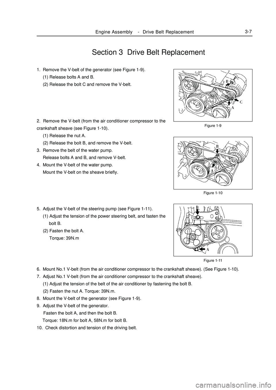
Section 3 Drive Belt Replacement1. Remove the V-belt of the generator (see Figure 1-9).
(1) Release bolts A and B.
(2) Release the bolt C and remove the V-belt.
2. Remove the V-belt (from the air conditioner compressor to the
crankshaft sheave (see Figure 1-10).
(1) Release the nut A.
(2) Release the bolt B, and remove the V-belt.
3. Remove the belt of the water pump.
Release bolts A and B, and remove V-belt.
4. Mount the V-belt of the water pump.
Mount the V-belt on the sheave briefly.
5. Adjust the V-belt of the steering pump (see Figure 1-11).
(1) Adjust the tension of the power steering belt, and fasten the
bolt B.
(2) Fasten the bolt A.
Torque: 39N.mFigure 1-9
Figure 1-10
Figure 1-11Engine AssemblyDrive Belt Replacement3-76. Mount No.1 V-belt (from the air conditioner compressor to the crankshaft sheave). (See Figure 1-10).
7. Adjust No.1 V-belt (from the air conditioner compressor to the crankshaft sheave).
(1) Adjust the tension of the belt of the air conditioner by fastening the bolt B.
(2) Fasten the nut A. Torque: 39N.m.
8. Mount the V-belt of the generator (see Figure 1-9).
9. Adjust the V-belt of the generator.
Fasten the bolt A, and then the bolt B.
Torque: 18N.m for bolt A, 58N.m for bolt B.
10. Check distortion and tension of the driving belt. -
Page 58 of 416
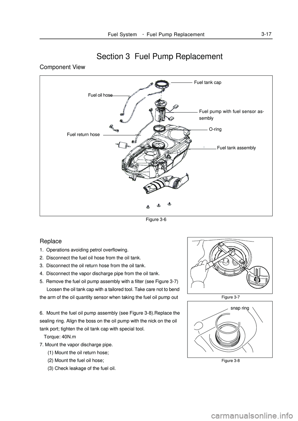
Section 3 Fuel Pump ReplacementComponent ViewFigure 3-6Replace1. Operations avoiding petrol overflowing.
2. Disconnect the fuel oil hose from the oil tank.
3. Disconnect the oil return hose from the oil tank.
4. Disconnect the vapor discharge pipe from the oil tank.
5. Remove the fuel oil pump assembly with a filter (see Figure 3-7)
Loosen the oil tank cap with a tailored tool. Take care not to bend
the arm of the oil quantity sensor when taking the fuel oil pump out
6. Mount the fuel oil pump assembly (see Figure 3-8).Replace the
sealing ring. Align the boss on the oil pump with the nick on the oil
tank port; tighten the oil tank cap with special tool.
Torque: 40N.m
7. Mount the vapor discharge pipe.
(1) Mount the oil return hose;
(2) Mount the fuel oil hose;
(3) Check leakage of the fuel oil.Figure 3-7
Figure 3-8Fuel SystemFuel Pump Replacement3-17Fuel tank cap
Fuel pump with fuel sensor as-
sembly
O-ring
Fuel tank assembly Fuel return hoseFuel oil hose
snap ring -
Page 62 of 416

Chapter IV Exhaust SystemComponent View
Replace1. Remove the tail exhaust pipe assembly.
Remove 2 bolts and the tail exhaust pipe assembly.
2. Remove the middle exhaust pipe assembly.
Replace the exhaust system.
Remove 2 bolts and the middle exhaust pipe assembly.
3. Remove the front exhaust pipe assembly.
Remove 2 bolts and the front exhaust pipe assembly.
4. Mount the front exhaust pipe assembly.
Measure the free length of the spring with a slide caliper.
Free length: 42mmFigure 4-1
Figure 4-2Exhaust SystemExhaust System3-21Center Muffer
Front MufferRear MufferThree-way Catalytic ConverterRear Rubber
BracketFront Rubber Bracket Mount the front exhaust pipe on the exhaust manifold with new washer.
Notes:
Do not use the removed washer any more.
5. Mount the front exhaust pipe assembly.
Torque: 43N.m
6. Mount the middle exhaust pipe assembly.
Mount the middle exhaust pipe on the front exhaust pipe with new washer.
Torque: 44N.m
7. Mount the tail exhaust pipe assembly.
Mount the tail exhaust pipe on the middle exhaust pipe with new washer. (see Figure 4-2).
Torque: 43N.m
8. Check exhaust leakage.washer Tail pipe side Suitable for 1.5L/1.6L(Tight coupling)
Suitable for 1.3L/1.5L(Non-tight coupling) -