wiring GEELY MK 2008 User Guide
[x] Cancel search | Manufacturer: GEELY, Model Year: 2008, Model line: MK, Model: GEELY MK 2008Pages: 416, PDF Size: 25.19 MB
Page 199 of 416

Check voltage between terminals
Standard:7.5-9V
0Voltage changes alternatively5-12 b. Check speed sensor
Check on state
Check connection between terminals
Standard:Tester connection Conditions Standard condition
3- ground Turn ignition switch to ON position 7. 5-9VTester connection Condition Standard condition
2- ground Normal ON Result and measures:
Abnormal, repair or replace wiring harness or connector
Normal, check speed sensor output signal
c. Check speed sensor output signal
Check voltage
Prop up two front wheels
Push transmission lever to neutral position
Turn on ignition switch
Turn front wheel slowly, measure the voltage between terminal 1 and terminal 2
Standard voltage is shown in the figure below:
Rotating wheel Below 0.5V
Result and measures:
Normal, repair or replace wiring harness or connector
Abnormal, replace speed sensor
(3) Check combination instrument assy.
a. Remove combination instrument assy. , disconnect connector.
b. Check on status
Check connection between terminals
Standard:
Tester connection Condition Standard condition
C 13- ground Normal ONCombination Instrument System -Malfunction Symptom Table and Troubleshooting
Page 200 of 416
5-13 c. Check voltage between terminals
Standard:Tester connectionConditions Standard condition
C 12- ground Turn ignition switch to ON position 7. 5-9V
Result and measures:
Abnormal, repair or replace wiring harness or connector
Normal, replace combination instrument assy.
3. Tachometer fails
Checkout procedure
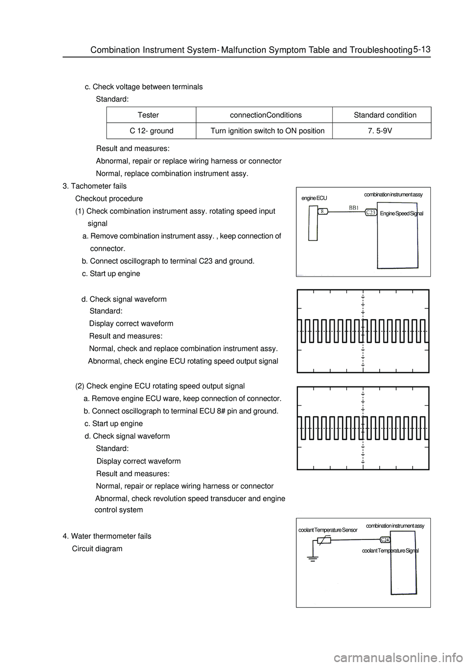
(1) Check combination instrument assy. rotating speed input
signal
a. Remove combination instrument assy. , keep connection of
connector.
b. Connect oscillograph to terminal C23 and ground.
c. Start up engine
d. Check signal waveform
Standard:
Display correct waveform
Result and measures:
Normal, check and replace combination instrument assy.
Abnormal, check engine ECU rotating speed output signal
(2) Check engine ECU rotating speed output signal
a. Remove engine ECU ware, keep connection of connector.
b. Connect oscillograph to terminal ECU 8# pin and ground.
c. Start up engine
d. Check signal waveform
Standard:
Display correct waveform
Result and measures:
Normal, repair or replace wiring harness or connector
Abnormal, check revolution speed transducer and engine
control system
4. Water thermometer fails
Circuit diagramCombination Instrument System -Malfunction Symptom Table and Troubleshooting combination instrument assy
combination instrument assy engine ECU
coolant Temperature SensorEngine Speed Signal
coolant Temperature Signal
Page 201 of 416
Tester connection Conditions Standard state
C(60°C)164.5±5 ohm
C 24- ground 1/2C(90°C)56±3 ohm
H(115°C)28.7±2 ohmConditions Standard state
C(60°C)164.5±5 ohm
1/2C(90°C)56±3 ohm
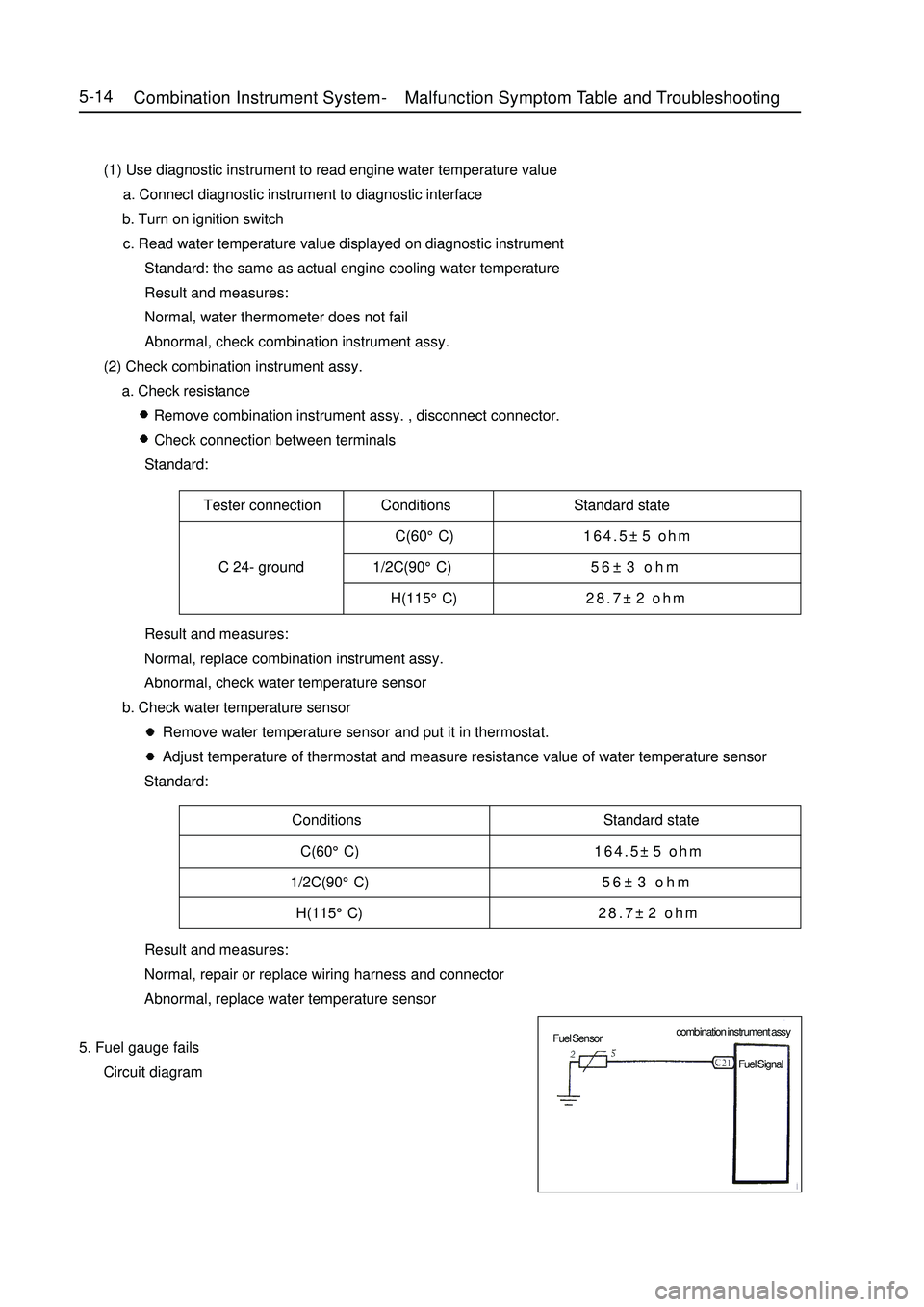
H(115°C)28.7±2 ohm5-14 (1) Use diagnostic instrument to read engine water temperature value
a. Connect diagnostic instrument to diagnostic interface
b. Turn on ignition switch
c. Read water temperature value displayed on diagnostic instrument
Standard: the same as actual engine cooling water temperature
Result and measures:
Normal, water thermometer does not fail
Abnormal, check combination instrument assy.
(2) Check combination instrument assy.
a. Check resistance
Remove combination instrument assy. , disconnect connector.
Check connection between terminals
Standard:
Result and measures:
Normal, replace combination instrument assy.
Abnormal, check water temperature sensor
b. Check water temperature sensor
Remove water temperature sensor and put it in thermostat.
Adjust temperature of thermostat and measure resistance value of water temperature sensor
Standard:
Result and measures:
Normal, repair or replace wiring harness and connector
Abnormal, replace water temperature sensor
5. Fuel gauge fails
Circuit diagramCombination Instrument System -Malfunction Symptom Table and Troubleshooting combination instrument assy
Fuel Sensor
Fuel Signal
Page 202 of 416
Tester connectionConditions Standard state
E 110±6 ohm
C 21- ground 1/232.5±3 ohm
F 3±2 ohmConditions Standard state5-15 (1) Check combination instrument assy.
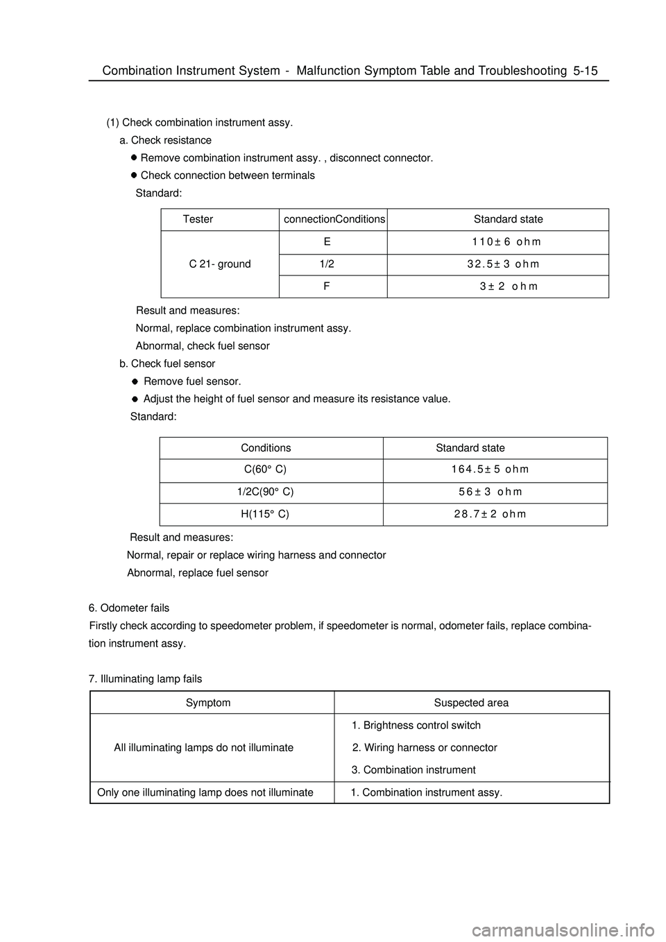
a. Check resistance
Remove combination instrument assy. , disconnect connector.
Check connection between terminals
Standard:
Result and measures:
Normal, replace combination instrument assy.
Abnormal, check fuel sensor
b. Check fuel sensor
Remove fuel sensor.
Adjust the height of fuel sensor and measure its resistance value.
Standard:
Result and measures:
Normal, repair or replace wiring harness and connector
Abnormal, replace fuel sensor
6. Odometer fails
Firstly check according to speedometer problem, if speedometer is normal, odometer fails, replace combina-
tion instrument assy.
7. Illuminating lamp fails
Symptom
All illuminating lamps do not illuminate
Only one illuminating lamp does not illuminateSuspected area
1. Brightness control switch
2. Wiring harness or connector
3. Combination instrument
1. Combination instrument assy.Combination Instrument System -Malfunction Symptom Table and Troubleshooting C(60°C)164.5±5 ohm
1/2C(90°C)56±3 ohm
H(115°C)28.7±2 ohm
Page 203 of 416

Suspected area
1. Wiring harness or connector
2. ECM
3. Combination instrument assy.
1. Wiring harness or connector
2. Alternator
3. Combination instrument assy.
1. Wiring harness or connector
2. Manual brake switch
3. Combination instrument assy.
1. Wiring harness or connector
2. Brake fluid level switch
3. Combination instrument assy.
1. Wiring harness or connector
2. ABS ECU or ABS warning lamp driving module
3. Combination instrument assy.
1. Wiring harness or connector
2. Airbag ECU controller
3. Combination instrument assy.
1. Wiring harness or connector
2. Airbag ECU controller
3. Combination instrument assy.
1. Wiring harness or connector
2. Front head light dimmer switch
3. Combination instrument assy.
1. Wiring harness or connector
2. Front head light dimmer switch
3. Combination instrument assy.
1. Wiring harness or connector
2. Rear defrost switch
3. Combination instrument assy. 8. Warning lamp fails
Symptom
Check that engine warning lamp does not
illuminate
Charge warning lamp does not illuminate
Park braking warning lamp does not
illuminate
Brake failure warning lamp does not
illuminate
ABS warning lamp does not illuminate
SRS warning lamp does not illuminate
Passenger's airbag indicator lamp does
not illuminate
High beam indicator lamp does not
illuminate
Rear foglight indicator lamp does not
illuminate
Rear defrost indicator lamp does not
illuminate5-16Combination Instrument System -Malfunction Symptom Table and Troubleshooting
Page 204 of 416

5-17Suspected area
1. Harness or connector.
2. Front fog switch
3. Combination instrument assy.
1. Wiring harness or connector
2. Cuolant temperature sensor
3. Combination instrument assy.
1. Wiring harness or connector
2. Safety belt buckle switch
3. Combination instrument assy. Symptom
Front fog switch lamp does not illuminate
Water temperature warning indicator lamp
does not illuminate
Safety belt warning indicator lamp does
not illuminateCombination Instrument System -Malfunction Symptom Table and Troubleshooting
Page 207 of 416

5-209. Check park warning lamp
(1) Disconnect connector from park switch
(2) Turn ignition switch to ON, park brake warning lamp should go out.
(3) Use conductor to short connector terminal to ground, park brake warning lamp should illuminate.
10. Check park switch
(1) Disconnect connector from park switch
(2) Pull up manual brake, check whether its terminal is connected with ground
Pull up manual brake: on
Manual brake release: off
11. Brake fluid level warning lamp
(1) Disconnect connector from brake fluid level sensor
(2) Turn ignition switch to ON, brake fluid level warning lamp should go out.
(3) Use conductor to connect its connector terminal wiring harness terminals directly, brake fluid level
warning lamp should illuminate.
12. Check brake fluid level warning switch
(1) Remove tank cap
(2) Disconnect connector from tank
(3) Check whether terminals are connected.
Floater on top: off
(4) Use sucker to suck out liquid from tank
(5) Check whether terminals are connected.
Floater down: on state
(6) Pour liquid back into tank
13. Rear defrost indicator lamp
(1) Turn ignition switch to ON, and start up engine
(2) Push down defrost switch, now rear defrost indicator lamp should illuminate
(3) Turn ignition switch to OFF, rear defrost indicator lamp should go out
14. Rear foglight indicator lamp
When rear foglight illuminates, rear foglight indicator lamp should illuminate, now A5 terminal should be high
potential.
15. Safety belt warning indicator lamp
(1) Disconnect safety belt switch connector from driver side, now safety belt warning indicator lamp should
go out.
(2) Short connector terminal to ground, safety belt warning indicator lamp should illuminate.Combination Instrument System -Malfunction Symptom Table and Troubleshooting
Page 229 of 416
Suspected Area
1. Wire between CD box and main unit
2. CD box
3. CD bag
4. CD PLAYER main unit
1. Wire between CD box and main unit
2. CD box
1. CD box
2. CD box installation Symptom
CD can not be taken out
Sound quality poor only when playing CD
(Volume faint)
CD sound jumpTester connection Condition Standard state
GND and vehicle earth Normal status ON
Tester connection Condition Standard state
+B and GND Normal status 10-14V
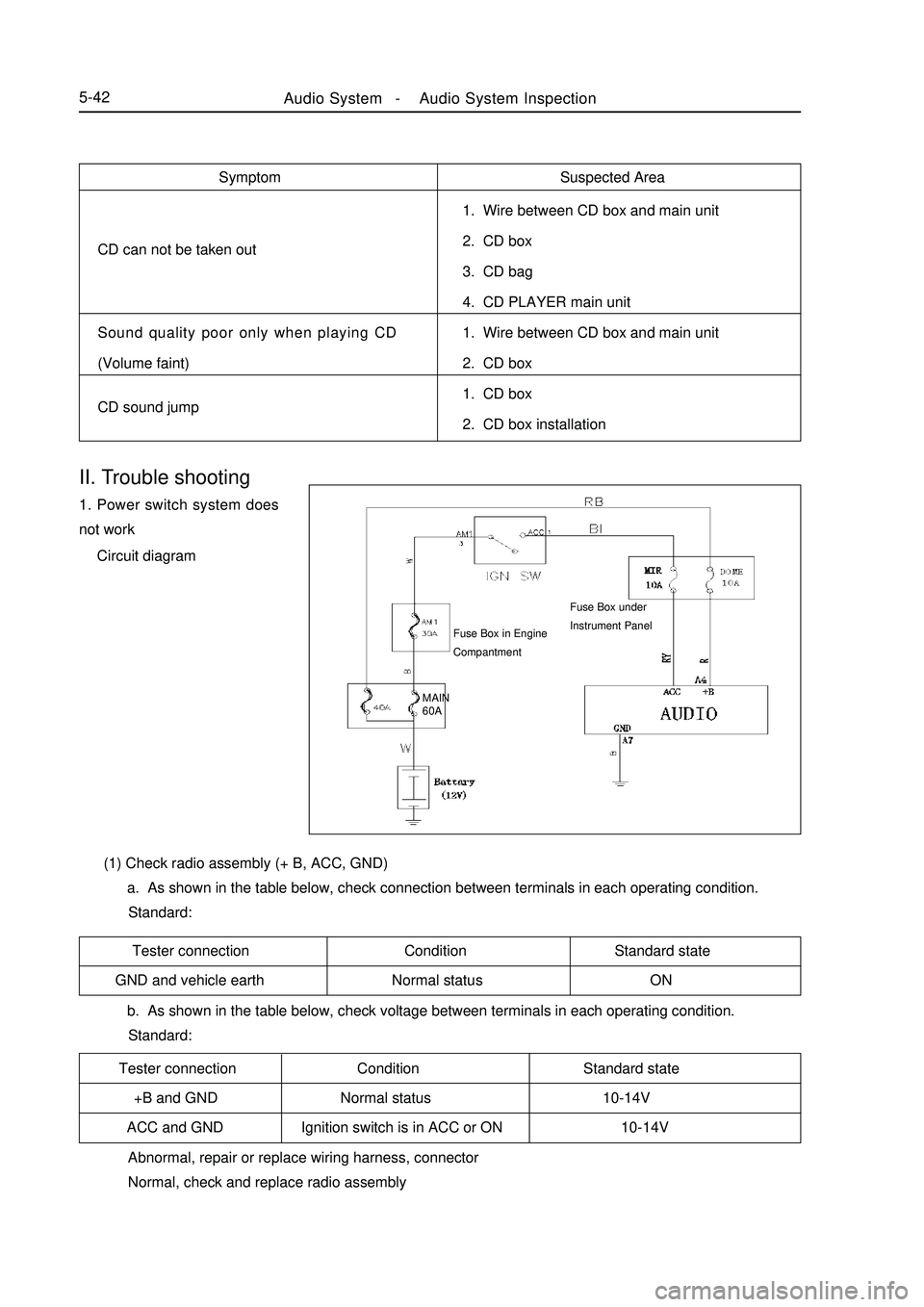
ACC and GND Ignition switch is in ACC or ON 10-14VII. Trouble shooting1. Power switch system does
not work
Circuit diagram
Abnormal, repair or replace wiring harness, connector
Normal, check and replace radio assembly (1) Check radio assembly (+ B, ACC, GND)
a. As shown in the table below, check connection between terminals in each operating condition.
Standard:
b. As shown in the table below, check voltage between terminals in each operating condition.
Standard:Fuse Box in Engine
CompantmentAudio System -Audio System Inspection5-42MAIN
60AFuse Box under
Instrument Panel
Page 230 of 416
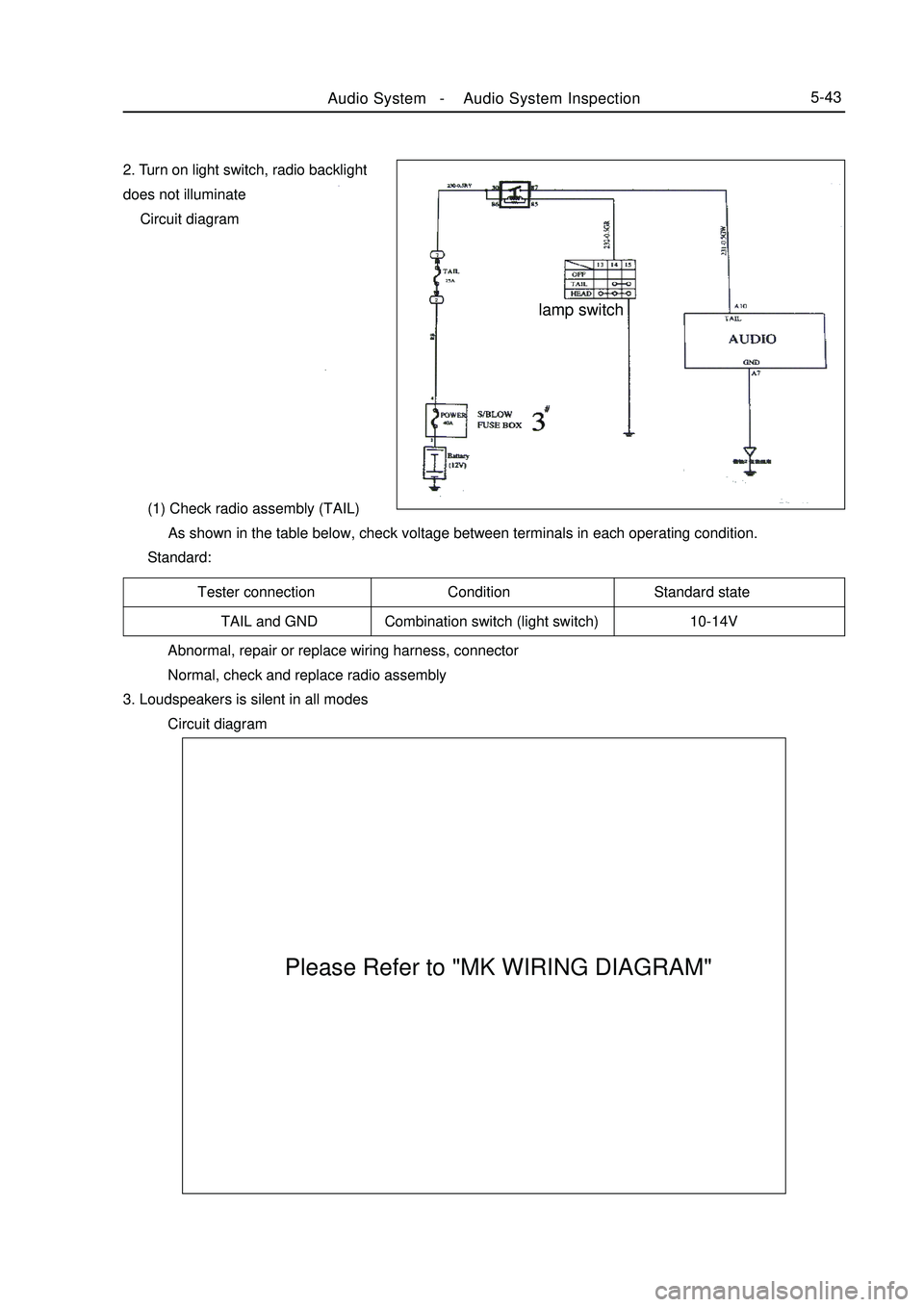
Tester connection Condition Standard state
TAIL and GND Combination switch (light switch) 10-14V2. Turn on light switch, radio backlight
does not illuminate
Circuit diagram
(1) Check radio assembly (TAIL)
As shown in the table below, check voltage between terminals in each operating condition.
Standard:
Abnormal, repair or replace wiring harness, connector
Normal, check and replace radio assembly
3. Loudspeakers is silent in all modes
Circuit diagramAudio System -Audio System Inspection5-43 lamp switch
Please Refer to "MK WIRING DIAGRAM"
Page 253 of 416

(2) Disconnect the connector of the wire harness.
(3) Remove the components of airbag assembly.
(4) Remove steering wheel.
Removal procedures of clock spring:
(1) Remove the driver airbag assembly (disconnect the connector).
(2) Remove steering wheel gently (see the precaution).
(3) Remove the steering column cover and disconnect the connector of wire harness in the lower end.
(4) Remove clock spring.
Installation procedures of the driver airbag assembly
(1) Pre-Check
1- Install steering wheel
2- Connect the wire harness
3- Install driver airbag assembly
4- Screw up the installation screws of the two sides
(2) Connection of the negative (-) terminal of the battery
(3) Check after installation.
Installation procedures of clock spring:
(1) Pre-Check
1- Connection and fixation of the clock spring and combination switch
2- the connector of wire harness in the lower end
3- the steering column cover
4-Thread the line at the upper end of the clock spring through hole on the body part of the steering wheel
5-Install the steering wheel
6-Connect wiring harness
7-Install the airbag assembly components
(2) Connect the negative (-) terminal cable of the battery
(3) Check after installation5-66Key points for installation
(1)Pre-Check
a. The new airbag or clock spring shall be checked before being installed.SRS (Supplemental Restraint System)-SRS-General InformationNotice
Use scanner to do adiagnossis of airbag circnit, not to break down.
Keep the removed driver airbag assembly upside down in a clean and dry place.Notice
Keep the removed clock sprint in a clean and dry place.fig.2Installation nutRemoval of steering wheel (see the figure 2)
(1) Remove the installation screws from the middle and remove
the steering wheel.(Disconnect the horn connector)