wheel bolt torque GEELY MK 2008 Owner's Manual
[x] Cancel search | Manufacturer: GEELY, Model Year: 2008, Model line: MK, Model: GEELY MK 2008Pages: 416, PDF Size: 25.19 MB
Page 179 of 416

Brake System -Rear Brake Drum4-10213. Check the brake shoe and the brake shoe lining whether they
touch normally.
Mark the inner surface of the brake drum with chalk, joint and
abrade the brake shoe and the inner surface.
If the drum and the lining touch poorly, abrade the brake shoe or
replace a new one.
14. Remove the left front or top brake wheel cylinder.
(1) Unfix the brake oil pipe with a special tool, and collect the
brake fluid with a container.
(2) Remove the bolt and brake wheel cylinder.
15. Remove the brake cup.
(1) Remove the two dust shields from the brake cylinder.
(2) Remove the two pistons and springs.
(3) Remove the two brake cylinder caps from every piston.
16. Check the brake cylinder.
Check the cylinder wall and piston whether there is any rust or nick.
17. Remove the rear discharge screw plug of the brake drum.
18. Tighten the rear discharge screw plug of the brake drum
temporarily.
19. Install the brake wheel cylinder cup.
(1) Apply the lithium soap-base glycol lube on the two brake
wheel cylinder cups and the piston.
(2) Install two brake cylinder caps on every piston.
(3) Install the compression spring and the two pistons on the
brake wheel cylinder.
(4) Install two new dust shields on the brake wheel cylinder.
20. Install the left front or top brake cylinder.
(1) Install the brake cylinder with bolt.
Torque: 9.8N.m
(2) Connect the brake oil pipe with a special tool.
Torque: 15N.m
21. Apply the heat-resistant lube.
Apply the heat-resistant lube on the touch surface of the brake
backboard and the brake shoe.
Page 184 of 416

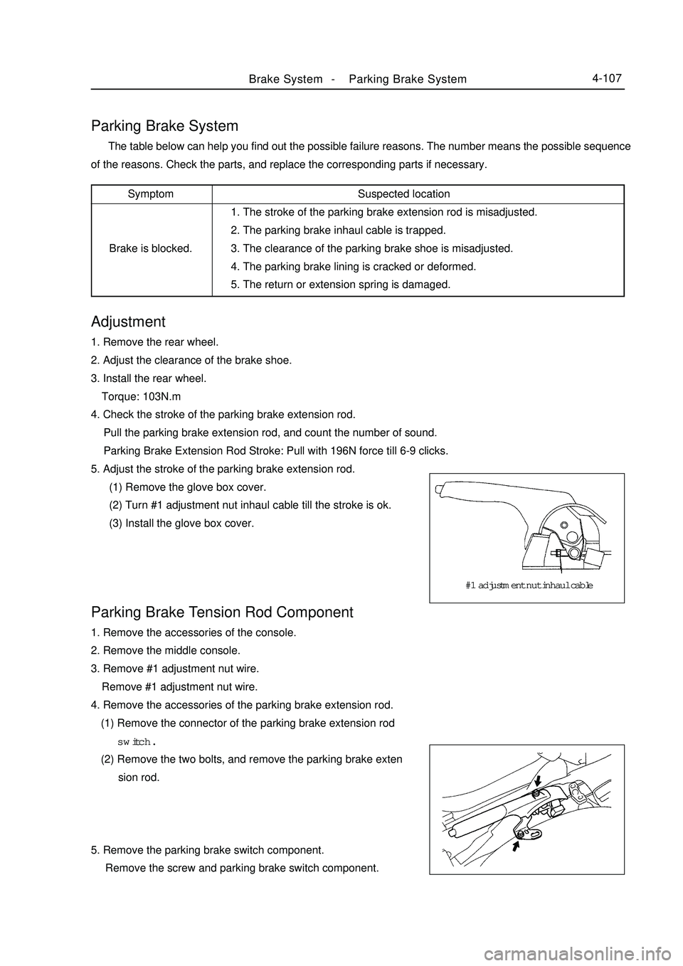
Brake System -Parking Brake System4-107Adjustment1. Remove the rear wheel.
2. Adjust the clearance of the brake shoe.
3. Install the rear wheel.
Torque: 103N.m
4. Check the stroke of the parking brake extension rod.
Pull the parking brake extension rod, and count the number of sound.
Parking Brake Extension Rod Stroke: Pull with 196N force till 6-9 clicks.
5. Adjust the stroke of the parking brake extension rod.
(1) Remove the glove box cover.
(2) Turn #1 adjustment nut inhaul cable till the stroke is ok.
(3) Install the glove box cover.Parking Brake System The table below can help you find out the possible failure reasons. The number means the possible sequence
of the reasons. Check the parts, and replace the corresponding parts if necessary.Parking Brake Tension Rod Component1. Remove the accessories of the console.
2. Remove the middle console.
3. Remove #1 adjustment nut wire.
Remove #1 adjustment nut wire.
4. Remove the accessories of the parking brake extension rod.
(1) Remove the connector of the parking brake extension rod
switch.
(2) Remove the two bolts, and remove the parking brake exten
sion rod.
5. Remove the parking brake switch component.
Remove the screw and parking brake switch component.Suspected location
1. The stroke of the parking brake extension rod is misadjusted.
2. The parking brake inhaul cable is trapped.
3. The clearance of the parking brake shoe is misadjusted.
4. The parking brake lining is cracked or deformed.
5. The return or extension spring is damaged.Symptom
Brake is blocked.#1 adjustment nut inhaul cable
Page 186 of 416

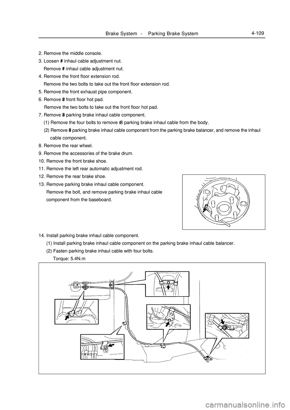
Brake System -Parking Brake System4-1092. Remove the middle console.
3. Loosen #1 inhaul cable adjustment nut.
Remove #1 inhaul cable adjustment nut.
4. Remove the front floor extension rod.
Remove the two bolts to take out the front floor extension rod.
5. Remove the front exhaust pipe component.
6. Remove #2 front floor hot pad.
Remove the two bolts to take out the front floor hot pad.
7. Remove #3 parking brake inhaul cable component.
(1) Remove the four bolts to remove # 3 parking brake inhaul cable from the body.
(2) Remove #3 parking brake inhaul cable component from the parking brake balancer, and remove the inhaul
cable component.
8. Remove the rear wheel.
9. Remove the accessories of the brake drum.
10. Remove the front brake shoe.
11. Remove the left rear automatic adjustment rod.
12. Remove the rear brake shoe.
13. Remove parking brake inhaul cable component.
Remove the bolt, and remove parking brake inhaul cable
component from the baseboard.
14. Install parking brake inhaul cable component.
(1) Install parking brake inhaul cable component on the parking brake inhaul cable balancer.
(2) Fasten parking brake inhaul cable with four bolts.
Torque: 5.4N.m
Page 187 of 416

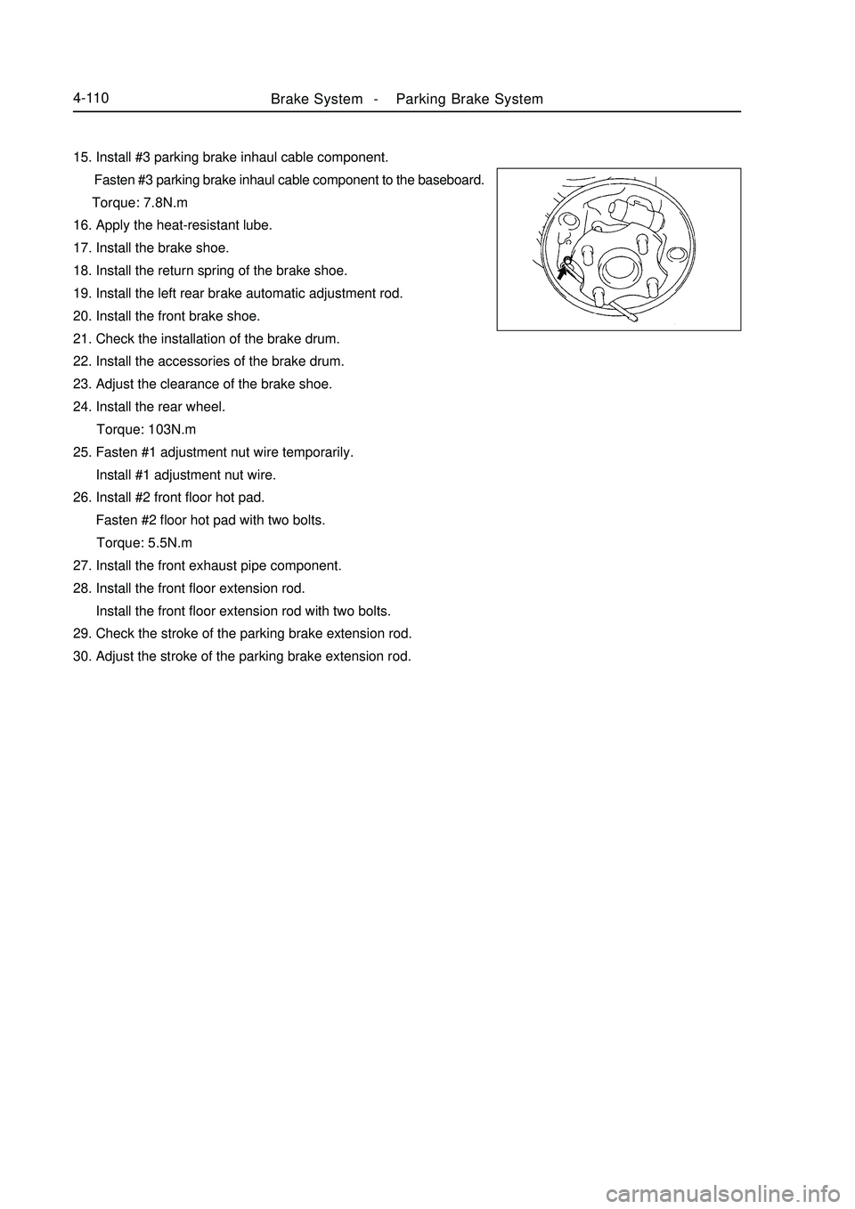
Brake System -Parking Brake System4-11015. Install #3 parking brake inhaul cable component.
Fasten #3 parking brake inhaul cable component to the baseboard.
Torque: 7.8N.m
16. Apply the heat-resistant lube.
17. Install the brake shoe.
18. Install the return spring of the brake shoe.
19. Install the left rear brake automatic adjustment rod.
20. Install the front brake shoe.
21. Check the installation of the brake drum.
22. Install the accessories of the brake drum.
23. Adjust the clearance of the brake shoe.
24. Install the rear wheel.
Torque: 103N.m
25. Fasten #1 adjustment nut wire temporarily.
Install #1 adjustment nut wire.
26. Install #2 front floor hot pad.
Fasten #2 floor hot pad with two bolts.
Torque: 5.5N.m
27. Install the front exhaust pipe component.
28. Install the front floor extension rod.
Install the front floor extension rod with two bolts.
29. Check the stroke of the parking brake extension rod.
30. Adjust the stroke of the parking brake extension rod.
Page 413 of 416

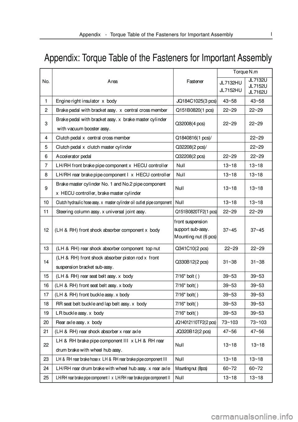
1 Engine right insulator x body JQ184C1025(3 pcs)43~58 43~58
2 Brake pedal with bracket assy. x central cross member Q151B0820(1 pcs)22~29 22~29
3Brake pedal with bracket assy. x brake master cylinder
Q32008(4 pcs)22~29 22~29
with vacuum booster assy.
4 Clutch pedal x central cross member Q1840816(1 pcs)/22~29
5 Clutch pedal x clutch master cylinder Q32208(2 pcs)/22~29
6 Accelerator pedal Q32208(2 pcs)22~29 22~29
7 LH/RH front brake pipe component x HECU controller Null13~18 13~18
8 LH/RH rear brake pipe component I x HECU controller Null13~18 13~18
9Brake master cylinder No. 1 and No.2 pipe component
Null13~18 13~18
x HECU controller, brake master cylinder
10Clutch hydraulic hose assy. x master cylinder oil outlet pipe componentNull13~18 13~18
11 Steering column assy. x universal joint assy.Q151B0820TF2(1 pcs)22~29 22~29
12 (LH & RH) front shock absorber component x body37~45 37~45
13 (LH & RH) rear shock absorber component top nut Q341C10(2 pcs) 22~29 22~29
14(LH & RH) front shock absorber piston rod x front
Q330B12(2 pcs)31~38 31~38
suspension bracket sub-assy.
15 (LH & RH) rear seat belt assy. x body7/16" bolt ( )39~53 39~53
16 (LH & RH) front seat belt assy. x body7/16" bolt( )39~53 39~53
17 (LH & RH) front buckle assy. x body7/16" bolt( )39~53 39~53
18 RR seat belt buckle and lap belt assy. x body7/16" bolt( )39~53 39~53
19 LR buckle assy. x body7/16" bolt( )39~53 39~53
20 Rear axle assy. x bodyJQ14012110TF2(2 pcs)73~103 73~103
21 (LH & RH) rear shock absorber x rear axle JQ320B12(2 pcs)47~56 47~56
22LH & RH brake pipe component III x LH & RH rear
Null13~18 13~18
drum brake with wheel hub assy.
23LH & RH rear brake hose x LH & RH rear brake pipe component IIINull13~18 13~18
24 LH/RH rear drum brake with wheel hub assy. x rear axleMounting nut (8pcs)60~72 60~72
25LH/RH rear brake pipe component I x LH/RH rear brake pipe component IINull13~18 13~18Appendix: Torque Table of the Fasteners for Important AssemblyTorque N.m
No.
JL7132HU
JL7152HUJL7132U
JL7152U
JL7162UAppendix-Torque Table of the Fasteners for Important AssemblyIArea Fastener
front suspension
support sub-assy.
Mounting nut (6 pcs)