torque GEELY MK 2008 Repair Manual
[x] Cancel search | Manufacturer: GEELY, Model Year: 2008, Model line: MK, Model: GEELY MK 2008Pages: 416, PDF Size: 25.19 MB
Page 152 of 416

Power Steering System-Power Steering Gear4-75Component ViewSection 4 Power Steering GearFront suspension crossmenber assembly125-15225-32
*28-35125-15227-3927-39
* :Special toolspecified torqueN.
m :PinGear rack power steering device
Pin
Page 153 of 416

Steering rack end sub-assembly
Steering rack end sub-assembly
Left ball extension shaft Left ball extension shaftComponent ViewPower Steering System-Power Steering Gear4-76Lock nut
Steering rack # 1 dust shield
Clip
Hoop
O-ring Steering hydraulic
oil pipe
O-ring
Hoop
Clip O-ring
Steering rack # 2 dust shield
Non-reusable parts
Power steering oil
Special toolLock nut
Specified torque
Page 154 of 416

Power Steering System-Power Steering Gear4-77Replacement1. Drain the power steering system fluid
2. Loosen the high pressure pipes.
Loosen the high pressure pipes with special tool
3. Loosen the low pressure pipes
Loosen the low pressure pipes with special tool
4. Separate the tie rod from the steering knuckle
(1) Remove the cotter pin, loosen the groove type lock nut
(2) Separate the tie rod ball stud joint from the steering knuckle
taper hole5. Loosen the thread screw of the high and low pressure pipe on the steering gear assembly
6. Remove the boot and press plate
7. Disconnect the power steering gear assembly from the steering column
Remove the steering gear pinion shaft spline lock bolt on the universal joint yoke
8. Remove power steering gear assembly
Remove 2 steering gear assembly set bolts. Remove the power steering gear assembly
9. Installation is in the reverse order of the removal
Notice:
(1) Insert the steering gear pinion shaft spline into the spline hole of the universal joint yoke, make sure that
the positions of the notch of the steering gear pinion shaft and the lock bolt of the universal joint yoke are
correct
(2) Secure the power steering gear with 2 bolts, torque: 125~152N.m
(3) Tighten the steering gear pinion shaft spline lock bolt on the universal joint yoke, torque: 22~34N.m
(4) Install the boot and press plate
(5) Install the threaded connector of the power steering high and low pressure pipe to the power steering gear,
torque: 25~32N.m
Page 155 of 416

Power Steering System
-Power Steering Gear4-78 (6) Connect the tie rod ball stud pin with the steering knuckle, make sure that the mating surface of the tie rod
ball stud pin and the steering knuckle is clean, tighten the slot nut, torque: 27~39N.m. Install the cotter pin,
make sure of the correct installation
(7) Add appropriate amount of specified power steering fluid, bleed the power steering system
(8) Check the power steering pipeline system for leakage
(9) Check the front wheel alignment and front wheel left and right limit turn angle, adjust the toe in if
necessary and tighten the tie rod lock nut
(10) Check the position of the steering wheel. It is required that the steering wheel spokes are basically
symmetrical when the vehicle is driven straight ahead, reassemble the steering wheel if necessary
Page 159 of 416

Component ViewSection 3 Brake PedalBrake pedal bracket
Lubrication bushing
Handspike pin
Pad
Clip
Brake pedal Brake light bushing25Brake System -Brake Pedal4-82Brake master cylinder
handspike U-connector
Brake light switch
Brake pedal axis
Brake pedal return spring
Brake pedal pad
Specified torque
Non-reusable parts
Lithium soap-base glycol lube
Page 160 of 416

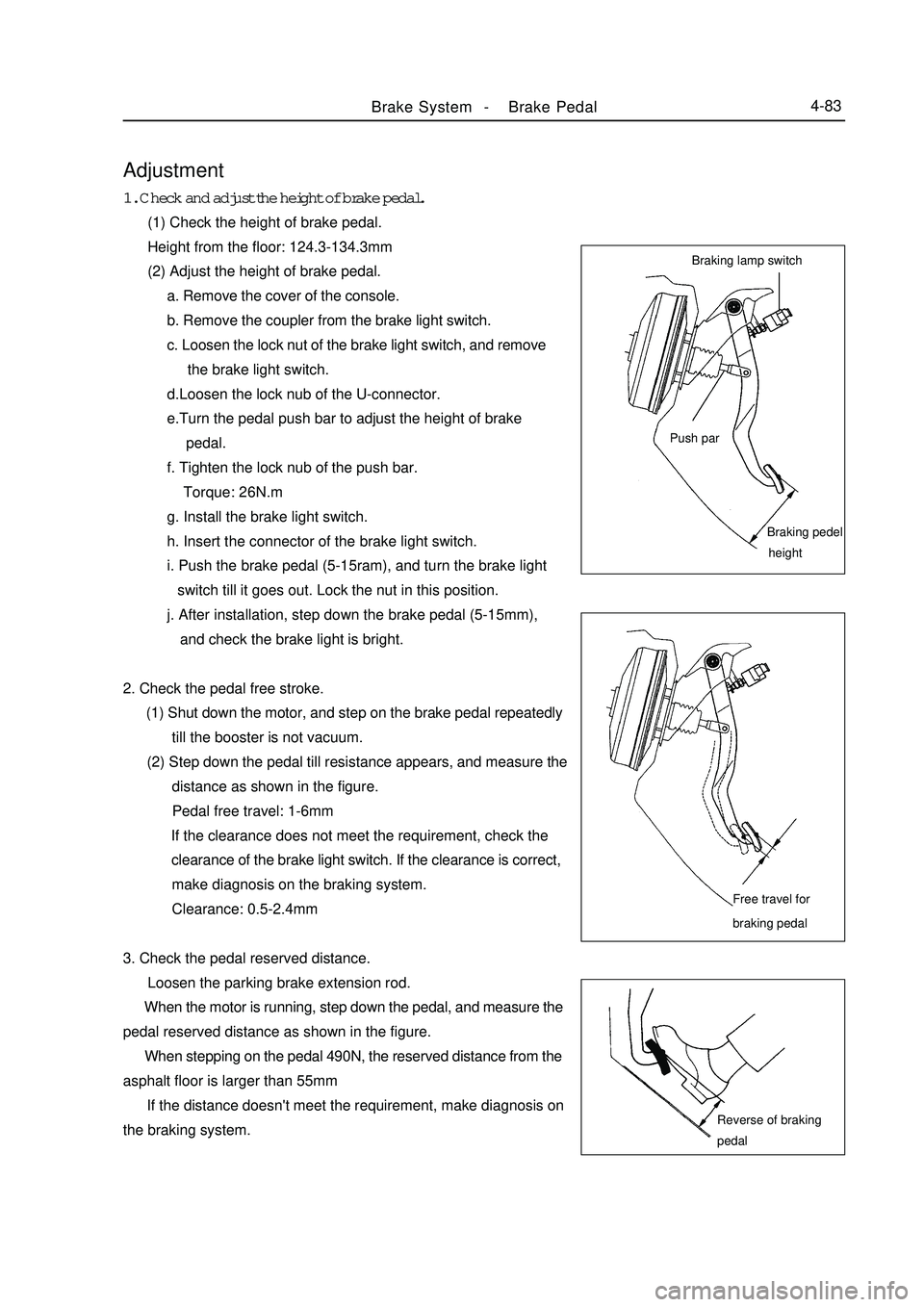
Adjustment1. Check and adjust the height of brake pedal.
(1) Check the height of brake pedal.
Height from the floor: 124.3-134.3mm
(2) Adjust the height of brake pedal.
a. Remove the cover of the console.
b. Remove the coupler from the brake light switch.
c. Loosen the lock nut of the brake light switch, and remove
the brake light switch.
d.Loosen the lock nub of the U-connector.
e.Turn the pedal push bar to adjust the height of brake
pedal.
f. Tighten the lock nub of the push bar.
Torque: 26N.m
g. Install the brake light switch.
h. Insert the connector of the brake light switch.
i. Push the brake pedal (5-15ram), and turn the brake light
switch till it goes out. Lock the nut in this position.
j. After installation, step down the brake pedal (5-15mm),
and check the brake light is bright.
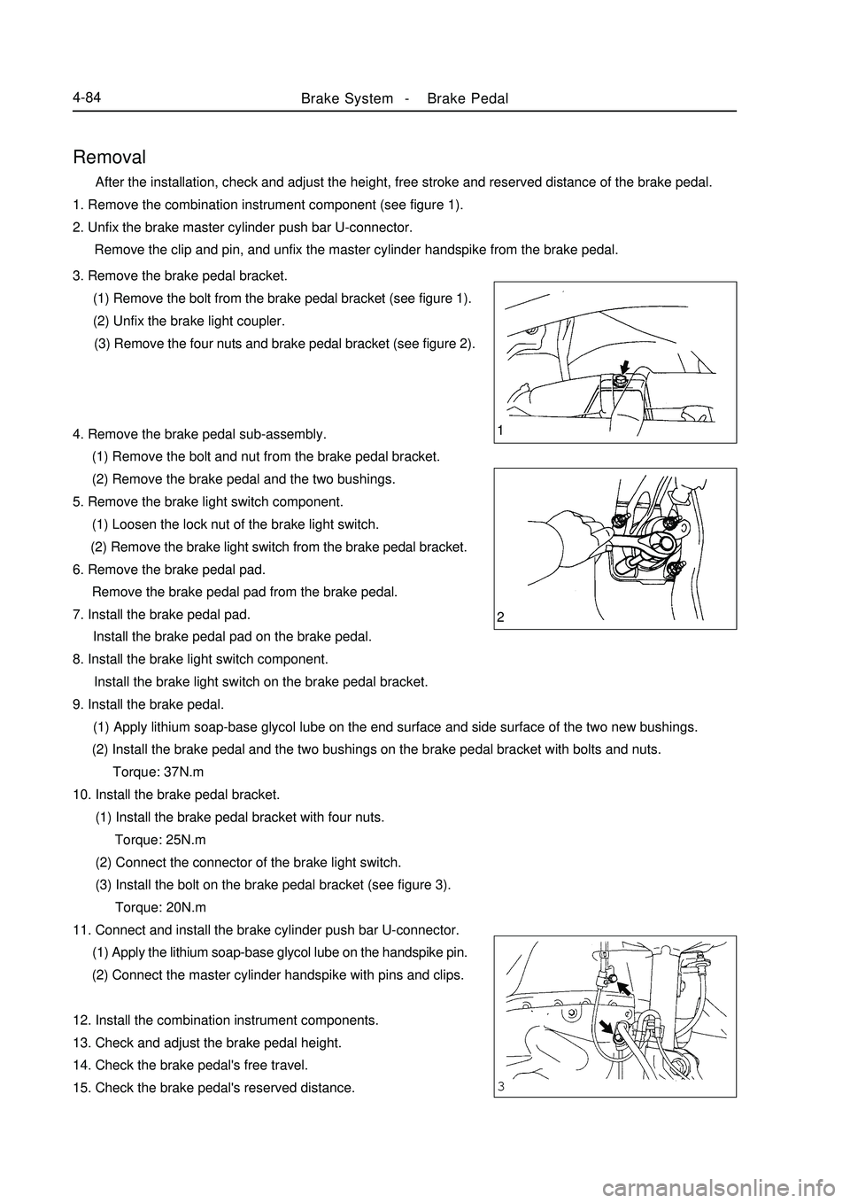
2. Check the pedal free stroke.
(1) Shut down the motor, and step on the brake pedal repeatedly
till the booster is not vacuum.
(2) Step down the pedal till resistance appears, and measure the
distance as shown in the figure.
Pedal free travel: 1-6mm
If the clearance does not meet the requirement, check the
clearance of the brake light switch. If the clearance is correct,
make diagnosis on the braking system.
Clearance: 0.5-2.4mm
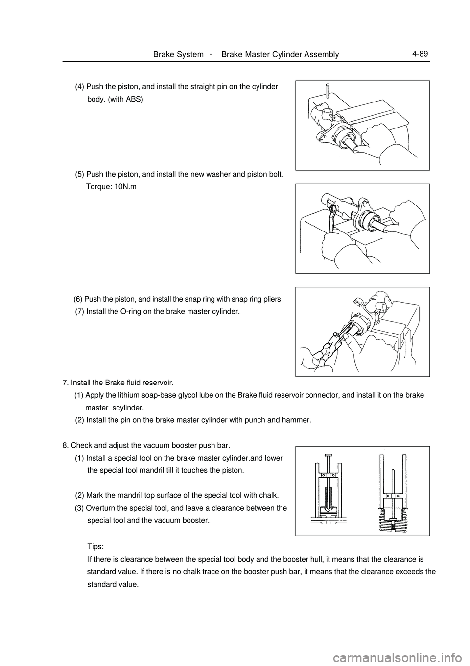
3. Check the pedal reserved distance.
Loosen the parking brake extension rod.
When the motor is running, step down the pedal, and measure the
pedal reserved distance as shown in the figure.
When stepping on the pedal 490N, the reserved distance from the
asphalt floor is larger than 55mm
If the distance doesn't meet the requirement, make diagnosis on
the braking system.Brake System -Brake Pedal4-83Braking lamp switch
Push parBraking pedel
heightFree travel for
braking pedalReverse of braking
pedal
Page 161 of 416

1
2
3Brake System -Brake Pedal4-84Removal After the installation, check and adjust the height, free stroke and reserved distance of the brake pedal.
1. Remove the combination instrument component (see figure 1).
2. Unfix the brake master cylinder push bar U-connector.
Remove the clip and pin, and unfix the master cylinder handspike from the brake pedal.
3. Remove the brake pedal bracket.
(1) Remove the bolt from the brake pedal bracket (see figure 1).
(2) Unfix the brake light coupler.
(3) Remove the four nuts and brake pedal bracket (see figure 2).
4. Remove the brake pedal sub-assembly.
(1) Remove the bolt and nut from the brake pedal bracket.
(2) Remove the brake pedal and the two bushings.
5. Remove the brake light switch component.
(1) Loosen the lock nut of the brake light switch.
(2) Remove the brake light switch from the brake pedal bracket.
6. Remove the brake pedal pad.
Remove the brake pedal pad from the brake pedal.
7. Install the brake pedal pad.
Install the brake pedal pad on the brake pedal.
8. Install the brake light switch component.
Install the brake light switch on the brake pedal bracket.
9. Install the brake pedal.
(1) Apply lithium soap-base glycol lube on the end surface and side surface of the two new bushings.
(2) Install the brake pedal and the two bushings on the brake pedal bracket with bolts and nuts.
Torque: 37N.m
10. Install the brake pedal bracket.
(1) Install the brake pedal bracket with four nuts.
Torque: 25N.m
(2) Connect the connector of the brake light switch.
(3) Install the bolt on the brake pedal bracket (see figure 3).
Torque: 20N.m
11. Connect and install the brake cylinder push bar U-connector.
(1) Apply the lithium soap-base glycol lube on the handspike pin.
(2) Connect the master cylinder handspike with pins and clips.
12. Install the combination instrument components.
13. Check and adjust the brake pedal height.
14. Check the brake pedal's free travel.
15. Check the brake pedal's reserved distance.
Page 162 of 416

Component ViewSection 4 Brake Master Cylinder AssemblyVacuum boosterBrake System -Brake Master Cylinder Assembly4-85Brake master cylinder
sub-assembly
Vacuum tube
Fluid level indicator lamp connector Manual Transmission
#1 clutch fluidr tank pipe No ABS
specified torqueN.
m :
Page 163 of 416

Component ViewBrake System -Brake Master Cylinder Assembly4-86With ABS:
Cover
Brake fluid reservoir
Strainer
Automatic Transmission
O-ring
Retaining ring
Pin
Straight pinPiston guide
block
Cup
Washer
#1 piston & Spring
#2 piston
Spring Hole connectorHole
connector
Master cylinder
Without ABS
Cover
Strainer
PinManual Transmission
O-ring
Retaining ring
Hole connector
Piston guide block
Cup
#1 piston & Spring
#2 piston & Spring
Washer
Piston limit bolt Master cylinder Hole connectorSpecified torque
Non-reusable parts
Lithium soap base glycol lube
Page 166 of 416

Brake System -Brake Master Cylinder Assembly4-89 (4) Push the piston, and install the straight pin on the cylinder
body. (with ABS)
(5) Push the piston, and install the new washer and piston bolt.
Torque: 10N.m
(6) Push the piston, and install the snap ring with snap ring pliers.
(7) Install the O-ring on the brake master cylinder.
7. Install the Brake fluid reservoir.
(1) Apply the lithium soap-base glycol lube on the Brake fluid reservoir connector, and install it on the brake
master scylinder.
(2) Install the pin on the brake master cylinder with punch and hammer.
8. Check and adjust the vacuum booster push bar.
(1) Install a special tool on the brake master cylinder,and lower
the special tool mandril till it touches the piston.
(2) Mark the mandril top surface of the special tool with chalk.
(3) Overturn the special tool, and leave a clearance between the
special tool and the vacuum booster.
Tips:
If there is clearance between the special tool body and the booster hull, it means that the clearance is
standard value. If there is no chalk trace on the booster push bar, it means that the clearance exceeds the
standard value.