ECU GENESIS G90 2017 Service Manual
[x] Cancel search | Manufacturer: GENESIS, Model Year: 2017, Model line: G90, Model: GENESIS G90 2017Pages: 524, PDF Size: 19.3 MB
Page 400 of 524

6-25
06
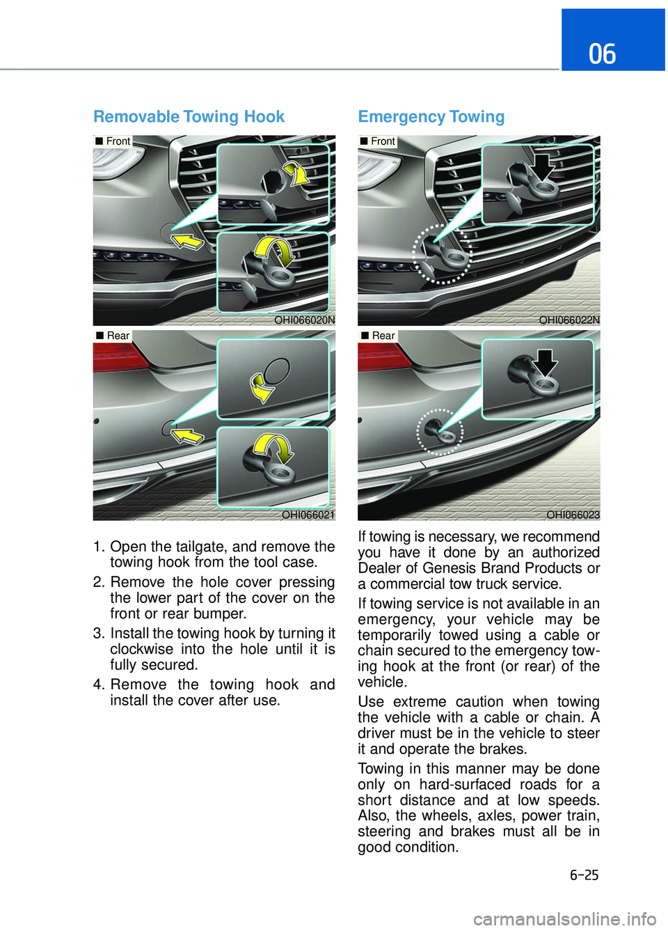
Removable Towing Hook
1. Open the tailgate, and remove thetowing hook from the tool case.
2. Remove the hole cover pressing the lower part of the cover on the
front or rear bumper.
3. Install the towing hook by turning it clockwise into the hole until it is
fully secured.
4. Remove the towing hook and install the cover after use.
Emergency Towing
If towing is necessary, we recommend
you have it done by an authorized
Dealer of Genesis Brand Products or
a commercial tow truck service.
If towing service is not available in an
emergency, your vehicle may be
temporarily towed using a cable or
chain secured to the emergency tow-
ing hook at the front (or rear) of the
vehicle.
Use extreme caution when towing
the vehicle with a cable or chain. A
driver must be in the vehicle to steer
it and operate the brakes.
Towing in this manner may be done
only on hard-surfaced roads for a
short distance and at low speeds.
Also, the wheels, axles, power train,
steering and brakes must all be in
good condition.
OHI066022N
■ Front
OHI066023
■ Rear
OHI066020N
OHI066021
■ Rear
■ Front
Page 401 of 524

6-26
What to do in an emergency
Always follow these emergency tow-
ing precautions:
Place the Engine Start/Stop button in the ACC position so the steering
wheel is not locked.
Place the shift lever in N (Neutral).
Release the parking brake.
Depress the brake pedal with more force than normal since you will
have reduced braking perform-
ance.
More steering effort will be required because the power steer-
ing system will be disabled.
Use a vehicle heavier than your own to tow your vehicle.
The drivers of both vehicles should communicate with each other fre-
quently.
Before emergency towing, check that the hook is not broken or dam-
aged.
Fasten the towing cable or chain securely to the hook.
Do not jerk the hook. Apply steady and even force. Use a towing cable or chain less
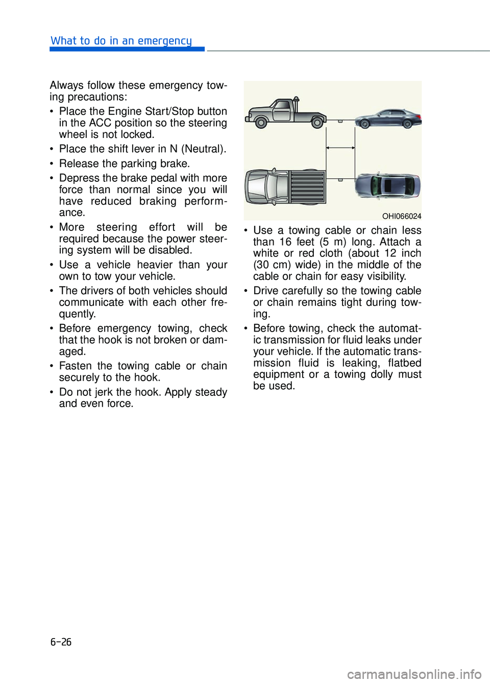
than 16 feet (5 m) long. Attach a
white or red cloth (about 12 inch
(30 cm) wide) in the middle of the
cable or chain for easy visibility.
Drive carefully so the towing cable or chain remains tight during tow-
ing.
Before towing, check the automat- ic transmission for fluid leaks under
your vehicle. If the automatic trans-
mission fluid is leaking, flatbed
equipment or a towing dolly must
be used.
OHI066024
Page 442 of 524

7-40
Maintenance
When you do not use the vehicle for a long time in a low tempera-
ture area, disconnect the battery
and keep it indoors.
Always charge the battery fully to prevent battery case damage
in low temperature areas.
For Best Battery Service
Keep the battery securely mount-ed.
Keep the battery top clean and dry.
Keep the terminals and connec- tions clean, tight, and coated with
petroleum jelly or terminal grease.
Rinse any spilled acid from the bat- tery immediately with a solution of
water and baking soda.
NOTICE
OHI076020N
CALIFORNIA PROPOSITION 65
WARNING
Battery posts, terminals, and
related accessories contain
lead and lead compounds,
chemicals known to the State of
California to cause cancer, birth
defects and reproductive harm.
Batteries also contain other
chemicals known to the State of
California to cause cancer.
Wash hands after handling.
WARNING■Trunk
Page 464 of 524

7-62
MaintenanceAfter checking the fuse box in the
engine compartment securely
close the fuse box cover inside
the engine compartment, until it
clicks.
If the fuse box is not closed prop-
erly, water may leak in side, possi-
bly causing a malfunction with the
electrical system.
Main fuse
If the main fuse is blown, it must be
removed as follows:
1. Turn off the engine.
2. Disconnect the negative battery cable.
3. Remove the fuse panel cover by pressing the tab and pulling it up.
4. Remove the nuts shown in the pic- ture above.
5. Replace the fuse with a new one of the same rating.
6. Reinstall in the reverse order of removal.
Information
If the main fuse is blown, consult an
authorized Dealer of Genesis Brand
Products.
Multi fuse
If the multi fuse is blown, it must be
removed as follows:
1. Turn off the engine.
2. Disconnect the negative batterycable.
3. Remove the fuse panel cover by pressing the tab and pulling it up.
4. Remove the nuts shown in the pic- ture above.
5. Replace the fuse with a new one of the same rating.
6. Reinstall in the reverse order of removal.
Information
If the multi fuse is blown, consult an
authorized Dealer of Genesis Brand
Products.
i
iNOTICE
OHI076026
OHI076027
Page 467 of 524

7-65
07
Instrument panel fuse panel
Fuse name Fuse rating Circuit protected
MODULE5 10AStop Lamp Switch, Driver/Passenger Door Module
MODULE7 10A
Electro Chromic Mirror, A/V & Navigation Head Unit, AMP,
A/C Control Module, Front A/C Controller, Air Quality
Sensor, Rear Seat Warmer Control Module LH/RH Head
Lamp LH/RH Driver/Passenger CCS Module
Rear CCS Module LH/RH, Driver/Passenger IMS Control
Module, Rear IMS Control Module LH/RH, Rear Seat
Console Switch
IBU3 10AIBU Control Module
E-SHIFTER2 10AElectronic ATM Shift Lever
MEMORY1 10A
Security Indicator, A/C Control Module, Front A/C Controller,
Instrument Cluster, Driver/Passenger IMS Control Module,
Rear IMS Control Module LH/RH, Head-Up Display, Analog
Clock
Driver/Passenger Seat Control Switch, Power Trunk Module,
Rear Seat Control Switch LH/RHM Driver/Passenger Smart
Key, Outside Handle Rear Smart Key Outside Handle
LH/RH
RR LH2P/SEAT25ARear IMS Control Module LH
DRIVER
P/SEAT225ADriver IMS Control Module
P/WINDOW RH30APassenger Power Window Module
Rear Power Window Module RH
MODULE 610A
Crash Pad Switch, Blind Spot Detection Radar LH/RH ECS
Unit, Electric Parking Brake Module, Lane Keeping Assist
Module, Front Console Switch, Steering Tilt & Telescopic
Module
MODULE 10 10ACooling Fan Controller (BLDC), Rear Seat Console Switch,
Around View Unit, Parking Guide Unit
MODULE3 10AGATEWAY (B+ (MCU)), Data Link Connector, Hazard
Switch
SUNROOF 25ASunroof Motor
PASSENGER P/SEAT2 25APassenger IMS Control Module
Page 472 of 524

7-70
Maintenance
Fuse name Fuse rating Circuit protected
POWER OUT-LET1 40A Metal Core Block (PCB #1 - Power Outlet Relay)
RR
BLOWER 30ARLY. 4 (Rear Blower Relay)
WIPER1 30AWiper Motor
DRIVER CCS 20A Driver CCS Module
PASSENGER CCS 20A Passenger CCS Module
POWER OUT-LET4 20A [W/O 5:5 Seat] Power Outlet Relay
4WD 30A 4WD ECM
PRESAFETYSEAT BELT1 30A Pre Active Seat Belt Unit
PRESAFETYSEAT BELT2 30APre Active Seat Belt Unit
DRIVER
P/DOOR 15ADriver Door Latch
PASSENGER P/DOOR 15APassenger Door Latch
RR LH
P/DOOR 15ARear Door Latch LH
RR RH
P/DOOR 15ARear Door Latch RH
IGN230AIG2 Relay
ECU330AEngine Control Relay
MODULE110A4WD ECM, Active Air Flap, Smart Cruse Control Radar
WIPER210APCB #2 (Wiper Relay)
WASHER20AWasher Relay
SENSOR210A[Lambda 3.3 T-GDI] Oxygen Sensor #1/#2/#3/#4
[Tau 5.0 GDI] Oxygen Sensor #1/#2/#3/#4, Electronic Thermostat
Page 473 of 524
![GENESIS G90 2017 Service Manual 7-71
07
Fuse name Fuse rating Circuit protected
SENSOR110A
[Lambda 3.3 T-GDI] Oil Controlvalve #1/#2/#3/#4(Intake/Exhaust), Purge Control
Solenoid Valve, Oil Pressure Solenoid
Valve, Canister Close Va GENESIS G90 2017 Service Manual 7-71
07
Fuse name Fuse rating Circuit protected
SENSOR110A
[Lambda 3.3 T-GDI] Oil Controlvalve #1/#2/#3/#4(Intake/Exhaust), Purge Control
Solenoid Valve, Oil Pressure Solenoid
Valve, Canister Close Va](/img/46/35652/w960_35652-472.png)
7-71
07
Fuse name Fuse rating Circuit protected
SENSOR110A
[Lambda 3.3 T-GDI] Oil Controlvalve #1/#2/#3/#4(Intake/Exhaust), Purge Control
Solenoid Valve, Oil Pressure Solenoid
Valve, Canister Close Valve
[Tau 5.0 GDI] Oil Controlvalve #1/#2/#3/#4 (Intake/ Exhaust), Purge Control Solenoid Valve,
Canister Close Valve
SENSOR310A[Lambda 3.3 T-GDI] Electronic Thermostat, Rear Sub Junction Block (Fuel Pump Relay)
[Tau 5.0 GDI] Rear Sub Junction Block (Fuel Pump Relay)
SENSOR410A
[Lambda 3.3 T-GDI] E/R Junction Block (RLY. 1 - Cooling Fan Relay)
[Tau 5.0 GDI] E/R Junction Block (RLY. 1 - Cooling Fan Relay), Camshaft Position Sensor #1/#2/#3/#4
(Intake/ Exhaust)
IGN COIL15A[Lambda 3.3 T-GDI] Ignition Coil #1/#2/#3/#4/#5/#6
[Tau 5.0 GDI] Ignition Coil #1/#2/#3/#4/#5/#6/#7/#8
ECU420AECM
H/LAMPHI SOL10AHead Lamp (HI SOL) Relay
H/LAMP
WASHER25AHead Lamp Washer Relay
A/CON110AA/C Control Module
FRT
BLOWER40AFront Blower Relay
IGN140AIG1 Relay
START30AE/R Junction Block (RLY. 2 - Start Relay)
ECU115AECM
TCU120ATCM
ESC310AESC Control Module
Page 474 of 524
![GENESIS G90 2017 Service Manual 7-72
Maintenance
Fuse name Fuse rating Circuit protected
MODULE210A4WD ECM, Active Air Flap, Smart Cruse Control Radar
MDPS210AMDPS Unit, Steering Angle Sensor
SENSOR510A[G6DP] E/R Junction Block (RLY GENESIS G90 2017 Service Manual 7-72
Maintenance
Fuse name Fuse rating Circuit protected
MODULE210A4WD ECM, Active Air Flap, Smart Cruse Control Radar
MDPS210AMDPS Unit, Steering Angle Sensor
SENSOR510A[G6DP] E/R Junction Block (RLY](/img/46/35652/w960_35652-473.png)
7-72
Maintenance
Fuse name Fuse rating Circuit protected
MODULE210A4WD ECM, Active Air Flap, Smart Cruse Control Radar
MDPS210AMDPS Unit, Steering Angle Sensor
SENSOR510A[G6DP] E/R Junction Block (RLY. 3 - Vacuum Pump- Relay),Brake Vacuum Switch
HORN20AHorn Relay
ECU210AECM
TCU215ATCM, B/UP Lamp Relay, P/N Relay
EPB215AElectric Parking Brake Module
EPB115AElectric Parking Brake Module
B/UP
LAMP10AB/Up Lamp Relay
ACC40AACC Relay
Page 509 of 524

Changing a Tire with TPMS ........................................................................\
........6-14
Checking tire inflation pressure ........................................................................\
...7-45
Child restraint system (CRS) ........................................................................\
.......2-45Booster seats........................................................................\
........................2-48
Children always in the rear ........................................................................\
.2-45
Forward-facing child restraint system ........................................................2-48
Installing a child restraint system (CRS) ....................................................2-48
Lower Anchors and tether for children .......................................................2-49
Rearward-facing child restraint system..................................\
.....................2-47
Securing a child restraint system seat with "Tether Anchor" system .........3-52
Securing a child restraint system with a lap/shoulder belt .........................3-53
Securing a child restraint with the the LATCH anchors system.................2-51
Selecting a child restraint system (CRS) ....................................................2-46
Child-protector rear door lock........................................................................\
......3-13
Clean air ........................................................................\
.....................................3-141
Climate control air filter........................................................................\
...............7-36
Clock ........................................................................\
..........................................3-151
Clothes hanger ........................................................................\
............................3-151
Combined instrument, see instrument cluster ......................................................3-60
Compact spare tire replacement ........................................................................\
...7-48
Consumer information........................................................................\
..................8-10
Coolant ........................................................................\
.........................................7-30
Cooling fluid, see engine coolant........................................................................\
.7-30
Crankcase emission control system .....................................................................7-8\
8
Cruise control system ........................................................................\
...................5-80
Cup holder ........................................................................\
..................................3-147
Curtain air bags ........................................................................\
............................2-62
Dashboard illumination, see instrument panel illumination ................................3-61
Dashboard, see instrument cluster .......................................................................3\
-60
Daytime running light (DRL) ........................................................................\
....3-107
Defogging (Windshield) ........................................................................\
.............3-138
Defroster ........................................................................\
.....................................3-121 Rear window defroster ........................................................................\
......3-121
Side view mirror defroster ........................................................................\
3-121
Defrosting (Windshield) ........................................................................\
.............3-138
Dimensions ........................................................................\
.....................................8-2
DIS navigation system ........................................................................\
...................4-4
Display illumination, see instrument panel illumination .....................................3-61
I-5
I
D