clock GENESIS G90 2017 Owner's Manual
[x] Cancel search | Manufacturer: GENESIS, Model Year: 2017, Model line: G90, Model: GENESIS G90 2017Pages: 524, PDF Size: 19.3 MB
Page 18 of 524
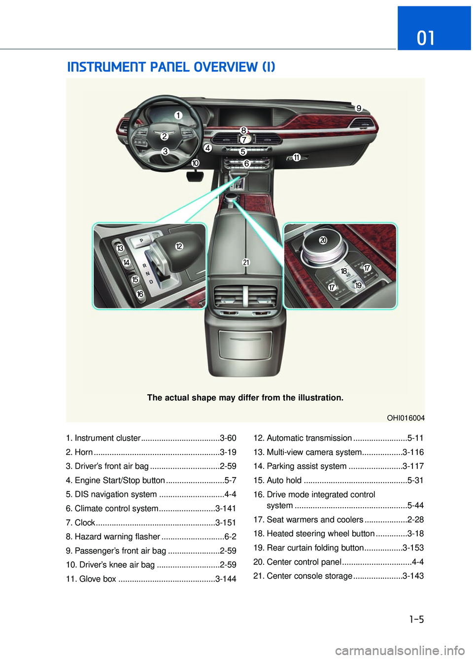
1. Instrument cluster ...................................3-60
2. Horn ........................................................3-19
3. Driver’s front air bag ...............................2-59
4. Engine Start/Stop button ..........................5-7
5. DIS navigation system .............................4-4
6. Climate control system.........................3-141
7. Clock .....................................................3-151
8. Hazard warning flasher ............................6-2
9. Passenger’s front air bag .......................2-59
10. Driver’s knee air bag ............................2-59
11. Glove box ...........................................3-14412. Automatic transmission ........................5-11
13. Multi-view camera system..................3-116
14. Parking assist system ........................3-117
15. Auto hold ..............................................5-31
16. Drive mode integrated control
system ..................................................5-44
17. Seat warmers and coolers ...................2-28
18. Heated steering wheel button ..............3-18
19. Rear curtain folding button .................3-153
20. Center control panel ...............................4-4
21. Center console storage ......................3-143
I I N
N S
ST
T R
R U
U M
M E
EN
N T
T
P
P A
A N
N E
EL
L
O
O V
VE
ER
R V
V I
IE
E W
W
(
( I
I)
)
1-5
01
The actual shape may differ from the illustration.
OHI016004
Page 27 of 524
2-7
02
Safety Precautions
Adjusting the seats so that you are sit-
ting in a safe, comfortable position
plays an important role in driver and
passenger safety together with the
seat belts and air bags in an accident.
Air bags
You can take steps to reduce the risk
of being injured by an inflating air
bag. Sitting too close to an air bag
greatly increases the risk of injury in
the event the air bag inflates.
The National Highway Traffic Safety
Administration (NHTSA) recommends
that drivers allow at least 10 inches
(25 cm) between the center of the
steering wheel and their chest.
Do not use a cushion that
reduces friction between the
seat and the passenger. The
passenger's hips may slide
under the lap portion of the seat
belt during an accident or a
sudden stop. Serious or fatal
internal injuries could result
because the seat belt cannot
operate properly.
WARNING
To reduce the risk of serious
injury or death from an inflating
air bag, take the following pre-
cautions:
• Adjust the driver's seat as far
to the rear as possible while
maintaining the ability to
maintain full control of the
vehicle.
Adjust the front passenger seat as far to the rear as pos-
sible.
Hold the steering wheel by the rim with hands at the 9 o'clock
and 3 o'clock positions to
minimize the risk of injuries to
your hands and arms.
NEVER place anything or any- one between the steering
wheel and the air bag.
Do not allow the front passen- ger to place feet or legs on the
dashboard to minimize the
risk of leg injuries.
WARNING
Page 81 of 524
2-61
02
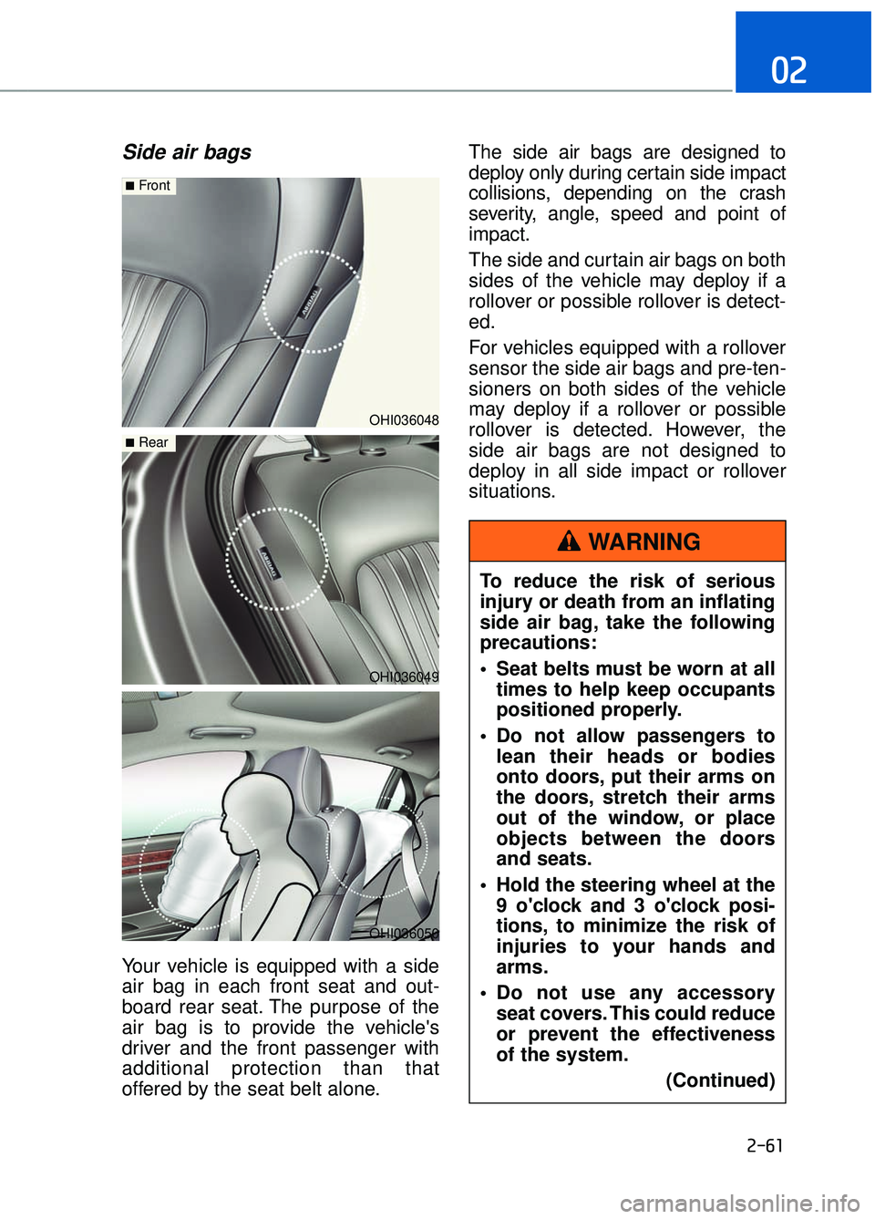
Side air bags
Your vehicle is equipped with a side
air bag in each front seat and out-
board rear seat. The purpose of the
air bag is to provide the vehicle's
driver and the front passenger with
additional protection than that
offered by the seat belt alone.The side air bags are designed to
deploy only during certain side impact
collisions, depending on the crash
severity, angle, speed and point of
impact.
The side and curtain air bags on both
sides of the vehicle may deploy if a
rollover or possible rollover is detect-
ed.
For vehicles equipped with a rollover
sensor the side air bags and pre-ten-
sioners on both sides of the vehicle
may deploy if a rollover or possible
rollover is detected. However, the
side air bags are not designed to
deploy in all side impact or rollover
situations.
OHI036048
■Front
OHI036049
■Rear
OHI036050
To reduce the risk of serious
injury or death from an inflating
side air bag, take the following
precautions:
Seat belts must be worn at all
times to help keep occupants
positioned properly.
Do not allow passengers to lean their heads or bodies
onto doors, put their arms on
the doors, stretch their arms
out of the window, or place
objects between the doors
and seats.
Hold the steering wheel at the 9 o'clock and 3 o'clock posi-
tions, to minimize the risk of
injuries to your hands and
arms.
Do not use any accessory seat covers. This could reduce
or prevent the effectiveness
of the system.
(Continued)
WARNING
Page 86 of 524
2-66
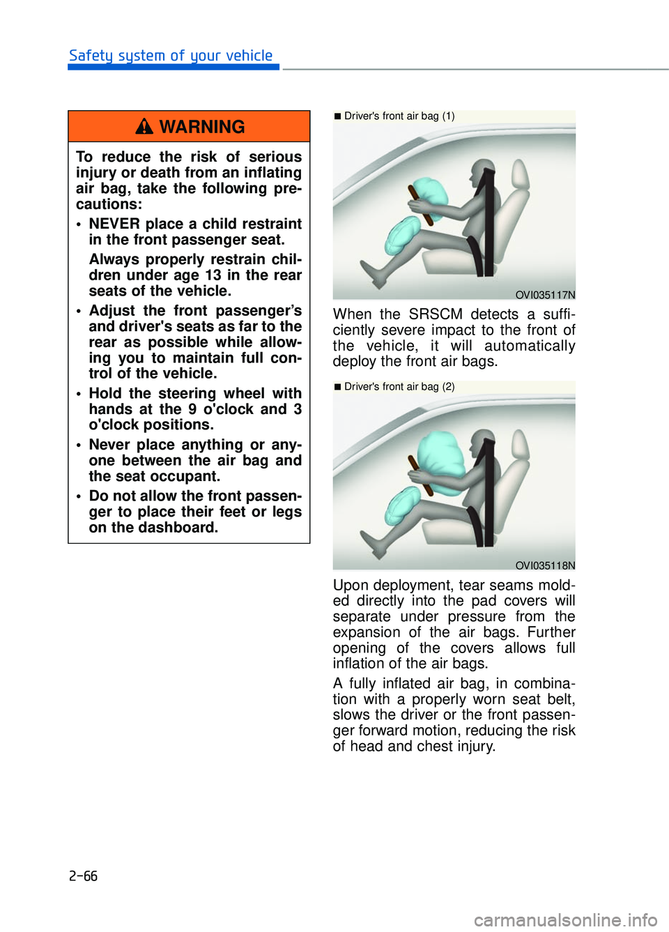
Safety system of your vehicleWhen the SRSCM detects a suffi-
ciently severe impact to the front of
the vehicle, it will automatically
deploy the front air bags.
Upon deployment, tear seams mold-
ed directly into the pad covers will
separate under pressure from the
expansion of the air bags. Further
opening of the covers allows full
inflation of the air bags.
A fully inflated air bag, in combina-
tion with a properly worn seat belt,
slows the driver or the front passen-
ger forward motion, reducing the risk
of head and chest injury.
To reduce the risk of serious
injury or death from an inflating
air bag, take the following pre-
cautions:
NEVER place a child restraint
in the front passenger seat.
Always properly restrain chil-
dren under age 13 in the rear
seats of the vehicle.
Adjust the front passenger’s and driver's seats as far to the
rear as possible while allow-
ing you to maintain full con-
trol of the vehicle.
Hold the steering wheel with hands at the 9 o'clock and 3
o'clock positions.
Never place anything or any- one between the air bag and
the seat occupant.
Do not allow the front passen- ger to place their feet or legs
on the dashboard.
WARNING
OVI035117N
■Driver's front air bag (1)
OVI035118N
■Driver's front air bag (2)
Page 105 of 524
C
Co
on
nv
ve
e n
n i
ie
e n
n t
t
f
f e
e a
at
tu
u r
re
e s
s
o
o f
f
y
y o
o u
ur
r
v
v e
e h
h i
ic
c l
le
e
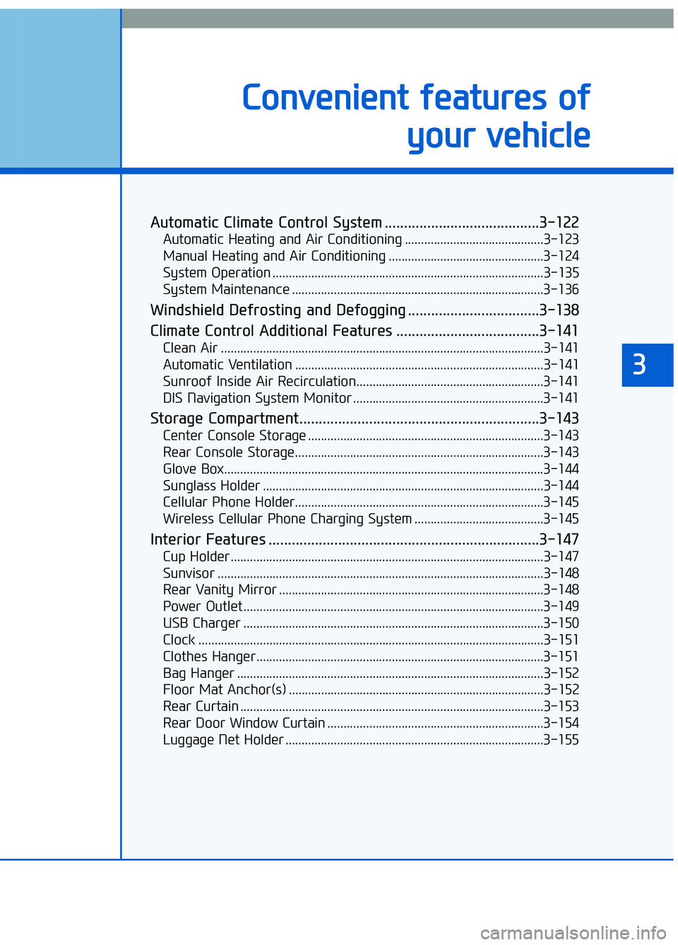
Automatic Climate Control System ........................................3-122
Automatic Heating and Air Conditioning ...........................................3-123
Manual Heating and Air Conditioning ................................................3-124
System Operation ........................................................................\
............3-135
System Maintenance ........................................................................\
......3-136
Windshield Defrosting and Defogging ..................................3-138
Climate Control Additional Features .....................................3-141
Clean Air ........................................................................\
............................3-141
Automatic Ventilation ........................................................................\
.....3-141
Sunroof Inside Air Recirculation..........................................................3-141
DIS Navigation System Monitor ...........................................................3-141
Storage Compartment..............................................................3-143
Center Console Storage ........................................................................\
.3-143
Rear Console Storage........................................................................\
.....3-143
Glove Box.......................................................................\
............................3-144
Sunglass Holder ........................................................................\
...............3-144
Cellular Phone Holder........................................................................\
.....3-145
Wireless Cellular Phone Charging System ........................................3-145
Interior Features ......................................................................3-\
147
Cup Holder........................................................................\
.........................3-147
Sunvisor ........................................................................\
.............................3-148
Rear Vanity Mirror ........................................................................\
..........3-148
Power Outlet ........................................................................\
.....................3-149
USB Charger ........................................................................\
.....................3-150
Clock ........................................................................\
...................................3-151
Clothes Hanger........................................................................\
.................3-151
Bag Hanger ........................................................................\
.......................3-152
Floor Mat Anchor(s) ........................................................................\
.......3-152
Rear Curtain ........................................................................\
......................3-153
Rear Door Window Curtain ...................................................................3-154\
Luggage Net Holder ........................................................................\
........3-155
3
Page 159 of 524
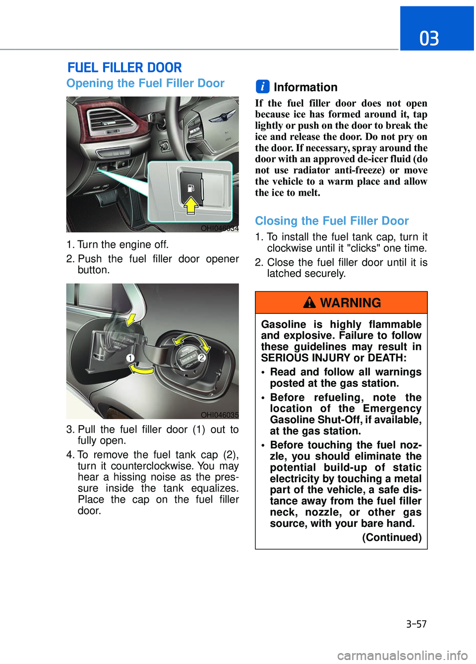
Opening the Fuel Filler Door
1. Turn the engine off.
2. Push the fuel filler door openerbutton.
3. Pull the fuel filler door (1) out to fully open.
4. To remove the fuel tank cap (2), turn it counterclockwise. You may
hear a hissing noise as the pres-
sure inside the tank equalizes.
Place the cap on the fuel filler
door.
Information
If the fuel filler door does not open
because ice has formed around it, tap
lightly or push on the door to break the
ice and release the door. Do not pry on
the door. If necessary, spray around the
door with an approved de-icer fluid (do
not use radiator anti-freeze) or move
the vehicle to a warm place and allow
the ice to melt.
Closing the Fuel Filler Door
1. To install the fuel tank cap, turn it clockwise until it "clicks" one time.
2. Close the fuel filler door until it is latched securely.
i
F FU
U E
EL
L
F
F I
IL
L L
LE
E R
R
D
D O
O O
OR
R
3-57
03
OHI046034
OHI046035
Gasoline is highly flammable
and explosive. Failure to follow
these guidelines may result in
SERIOUS INJURY or DEATH:
Read and follow all warnings
posted at the gas station.
Before refueling, note the location of the Emergency
Gasoline Shut-Off, if available,
at the gas station.
Before touching the fuel noz- zle, you should eliminate the
potential build-up of static
electricity by touching a metal
part of the vehicle, a safe dis-
tance away from the fuel filler
neck, nozzle, or other gas
source, with your bare hand.
(Continued)
WARNING
Page 253 of 524
3-151
03
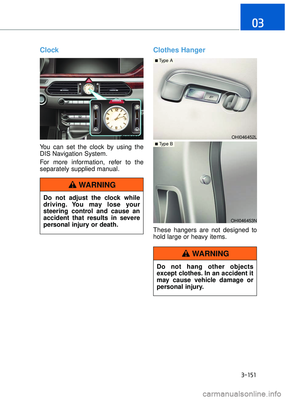
Clock
You can set the clock by using the
DIS Navigation System.
For more information, refer to the
separately supplied manual.
Clothes Hanger
These hangers are not designed to
hold large or heavy items.
OHI046451
Do not adjust the clock while
driving. You may lose your
steering control and cause an
accident that results in severe
personal injury or death.
WARNING
OHI046452L
■Type A
OHI046453N
■ Type B
Do not hang other objects
except clothes. In an accident it
may cause vehicle damage or
personal injury.
WARNING
Page 384 of 524
6-9
06
6. If you cannot find the cause of theoverheating, wait until the engine
temperature has returned to nor-
mal. Then, if coolant has been
lost, carefully add coolant to the
reservoir to bring the fluid level in
the reservoir up to the halfway
mark.
7. Proceed with caution, keeping alert for further signs of overheat-
ing. If overheating happens again,
call an authorized Dealer of
Genesis Brand Products for assis-
tance.
Serious loss of coolant indicates a
leak in the cooling system and
should be checked as soon as
possible by an authorized Dealer
of Genesis Brand Products.
NOTICE
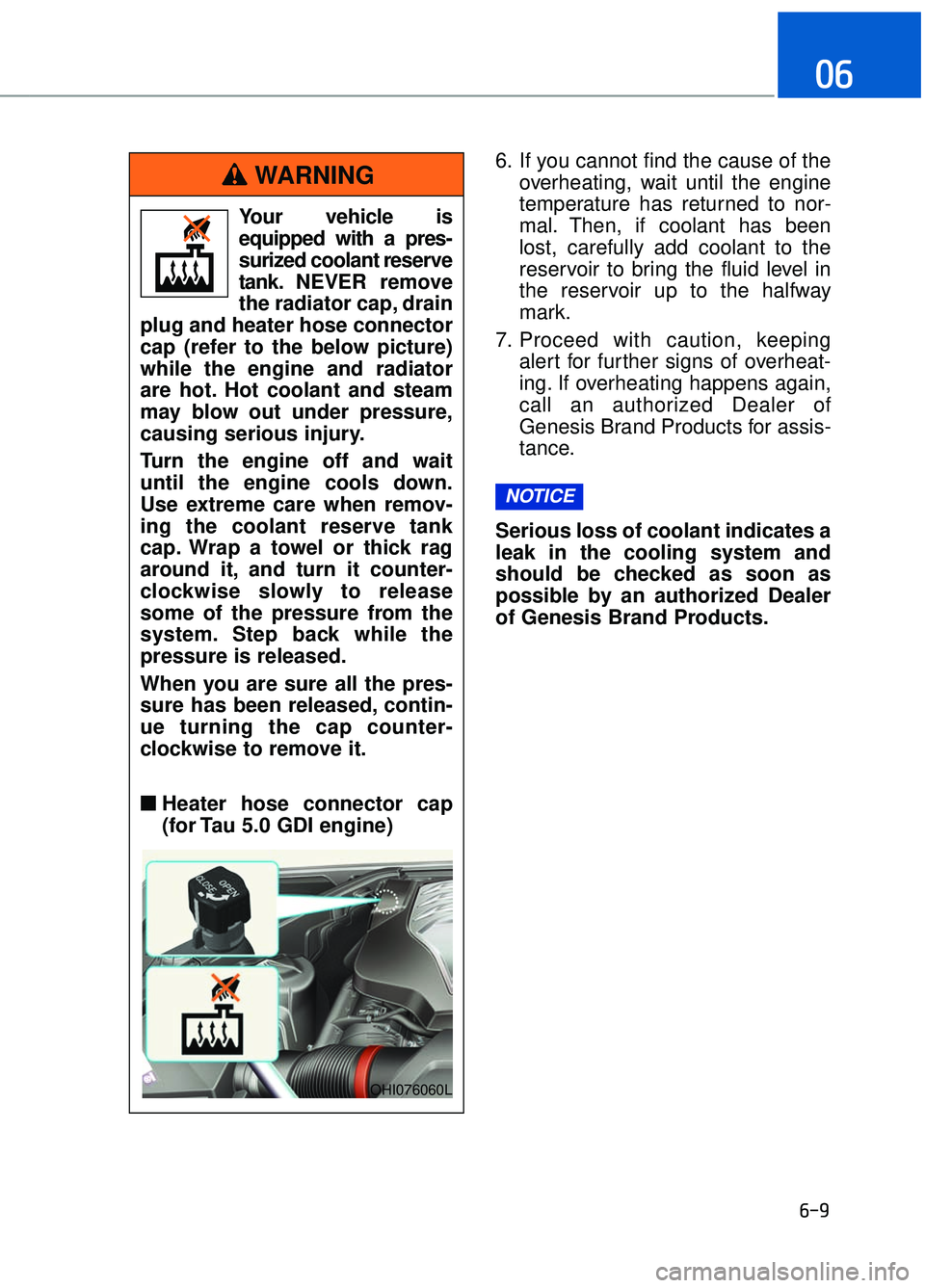
Your vehicle is
equipped with a pres-
surized coolant reserve
tank. NEVER remove
the radiator cap, drain
plug and heater hose connector
cap (refer to the below picture)
while the engine and radiator
are hot. Hot coolant and steam
may blow out under pressure,
causing serious injury.
Turn the engine off and wait
until the engine cools down.
Use extreme care when remov-
ing the coolant reserve tank
cap. Wrap a towel or thick rag
around it, and turn it counter-
clockwise slowly to release
some of the pressure from the
system. Step back while the
pressure is released.
When you are sure all the pres-
sure has been released, contin-
ue turning the cap counter-
clockwise to remove it.
■ ■ Heater hose connector cap
(for Tau 5.0 GDI engine)
WARNING
OHI076060L
Page 391 of 524
6-16
What to do in an emergency
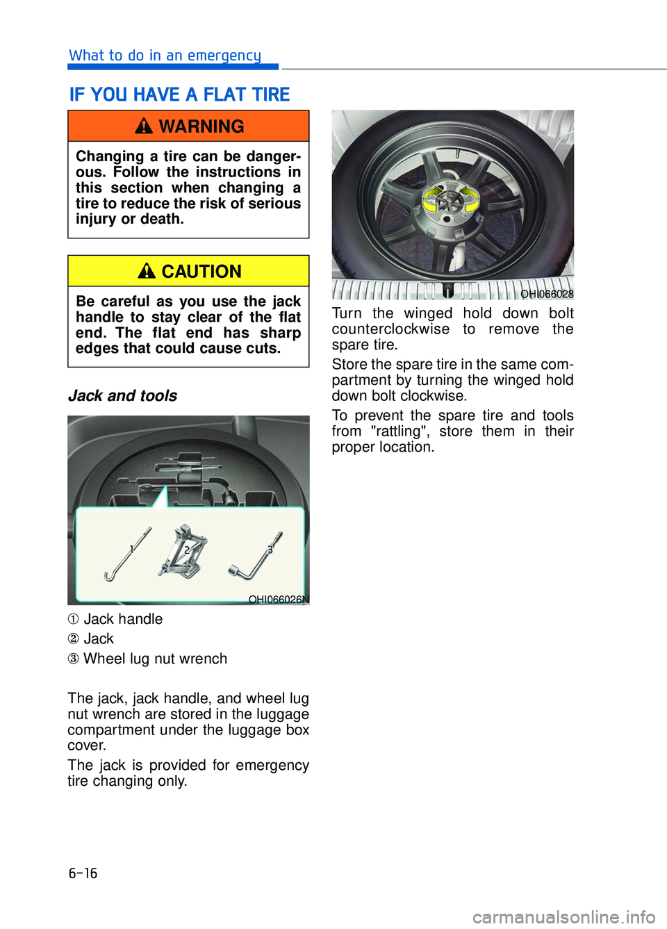
Jack and tools
➀Jack handle
② Jack
③ Wheel lug nut wrench
The jack, jack handle, and wheel lug
nut wrench are stored in the luggage
compartment under the luggage box
cover.
The jack is provided for emergency
tire changing only. Turn the winged hold down bolt
counterclockwise to remove the
spare tire.
Store the spare tire in the same com-
partment by turning the winged hold
down bolt clockwise.
To prevent the spare tire and tools
from "rattling", store them in their
proper location.
I I
F
F
Y
Y O
O U
U
H
H A
AV
VE
E
A
A
F
F L
LA
A T
T
T
T I
IR
R E
E
Changing a tire can be danger-
ous. Follow the instructions in
this section when changing a
tire to reduce the risk of serious
injury or death.
WARNING
OHI066028
OHI066026N
Be careful as you use the jack
handle to stay clear of the flat
end. The flat end has sharp
edges that could cause cuts.
CAUTION
Page 392 of 524

6-17
06
If it is hard to loosen the tire hold-
down wing bolt by hand, you can
loosen it easily using the jack handle.
1. Put the jack handle (1) inside ofthe tire hold-down wing bolt.
2. Turn the tire hold-down wing bolt counterclockwise with the jack
handle.
When you remove or store the
spare tire, do not contact or bump
the battery with the spare tire.
Contacting or bumping the battery
may cause failure of electrical cir-
cuits.
Changing tires
NOTICE
A vehicle can slip or roll off of a
jack causing serious injury or
death to you or those nearby.
Take the following safety pre-
cautions:
Never place any portion of your body under a vehicle that
is supported by a jack.
NEVER attempt to change a tire in the lane of traffic.
ALWAYS move the vehicle
completely off the road on
level, firm ground away from
traffic before trying to change
a tire. If you cannot find a
level, firm place off the road,
call a towing service for assis-
tance.
Be sure to use the jack provid- ed with the vehicle.
ALWAYS place the jack on the designated jacking positions
on the vehicle and NEVER on
the bumpers or any other part
of the vehicle for jacking sup-
port.
Do not start or run the engine while the vehicle is on the
jack.
Do not allow anyone to remain in the vehicle while it is on the
jack.
Keep children away from the road and the vehicle.
WARNING
OHI066029