battery GMC SIERRA DENALI 2003 Owners Manual
[x] Cancel search | Manufacturer: GMC, Model Year: 2003, Model line: SIERRA DENALI, Model: GMC SIERRA DENALI 2003Pages: 428, PDF Size: 20.35 MB
Page 6 of 428
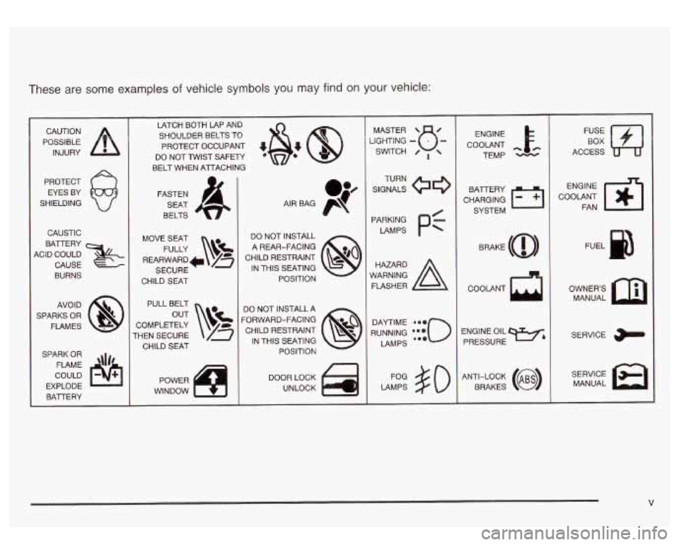
These are some examples of vehicle symbols you may find on your vehicle:
POSSIBLE /r
CAUTION
INJURY
PROTECT EYES BY
SHIELDING
CAUSTIC
ACID COULD BATTERY
CAUSE
BURNS
AVOID
SPARKS
OR
FLAMES
SPARK
OR
COULD FLAME
'\Ir8
EXPLODE
BAlTERY LATCH BOTH LAP AND
SHOULDER BELTS TO
PROTECT OCCUPANT
48: @
DO NOT TWIST SAFm
BELT WHEN AlTACHING
FASTEN SEAT
BELTS
MOVE SEAT FULLY
\v!
REARWARD* /g
SECURE
CHILD SEAT
PULL BELT
COMPLETELY
THEN SECURE CHILD
SEAT
DO NOT INSTALL
A REAR-FACING
CHILD RESTRAINT
@o
POSITION 8
IN THIS SEATING
DO NOT INSTALL
A
CHILD RESTRAINT p?
FORWARD-FACING IN THIS SEATING POSITION
8
DOOR LOCK
UNLOCK SGHTING
- MASTER SWITCH B- / ,
SIGNALS @e
TURN
PARKING
PC
LAMPS
RUNNING
*:{io
DAYTIME LAMPS
LAMPS
#O
ENGINE
COOLANT
cc.
TEMP
CHARGING BAlTERY
SYSTEM
COOLANT
ENGINE OIL PRESSURE
W&
ANTI-LOCK (@)
BRAKES
FE E]
ACCESS
COOLANT
m-1
ENGINE FAN
OWNERS MANUAL
SERVICE
MANUAL
V
Page 79 of 428
Servicing Your Air Bag-Equipped
Vehicle
Air bags affect how your vehicle should be serviced.
There are parts of the air bag system in several places
around your vehicle. You don’t want the system to
inflate while someone
is working on your vehicle. Your
dealer and the service manual have information
about servicing your vehicle and the air bag system. To
purchase a service manual, see
Service Publications
Order’ Information
on page 7- 10.
E
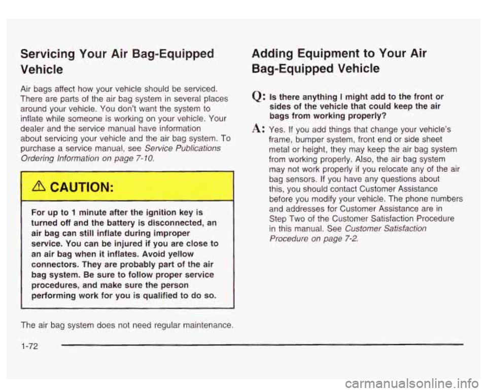
For up to 1 minute after the il tiol :ey is
turned off and the battery is disconnected, an
air bag can
still inflate during improper
service. You can be injured if you are close to
an air bag when
it inflates. Avoid yellow
connectors. They are probably part of the air bag system. Be sure to follow proper service
procedures, and make sure the person performing work for you
is qualified to do so.
Adding Equipment to Your Air
Bag-Equipped Vehicle
Q: Is there anything I might add to the front or
sides of the vehicle that could keep the air
bags from working properly?
frame, bumper system, front end or side sheet
metal or height, they may keep the air bag system
from working properly. Also, the air bag system
may not work properly
if you relocate any of the air
bag sensors.
If you have any questions about
this, you should contact Customer Assistance
before you modify your vehicle. The phone numbers
and addresses for Customer Assistance are in
Step Two of the Customer Satisfaction Procedure
in this manual. See
Customer Satisfaction
Procedure
on page 7-2.
A: Yes. If you add things that change your vehicle’s
The air bag system does not need regular maintenance.
1 -72
Page 85 of 428
At times you may notice a decrease in range. This is
normal for any remote keyless entry system. If the
transmitter does not work or
if you have to stand closer
to your vehicle for the transmitter to work, try this:
Check the distance. You may be too far from your
vehicle. You may need to stand closer during
rainy or snowy weather.
Check the location. Other vehicles or objects may be
blocking the signal. Take a few steps to the left or
right, hold the transmitter higher, and try again.
Check to determine if battery replacement is
necessary. See “Battery Replacement” under
Remote Keyless Entry System Operation on
page
2-4.
qualified technician for service.
If you are still having trouble, see your dealer or a
Remote Keyless Entry System
Operation
You can lock and unlock your doors from about 3 feet
(1 m) up to 100 feet (30 m) away using the remote
keyless entry transmitter supplied with your vehicle. UNLOCK:
Pressing this button once will unlock the
driver’s door. The interior lamps will come on. Pressing
UNLOCK again within three seconds will cause the
remaining doors to unlock.
You can choose different feedback options for each
press of the UNLOCK button. See
DlC Operation and
Displays on page
3-43 for more information.
LOCK: Pressing this button once will lock all of the
doors. You can choose different feedback options
for each press of the LOCK button. See
DlC Operation
and Displays on page
3-43 for more information.
Operating the keyless entry transmitter may interact with
the theft-deterrent system. See
Content Theft-Deterrent
on page
2- 13 and DlC Operation and Displays on
page
3-43 for more information.
Remote Alarm
When the horn symbol on the keyless entry transmitter
is pressed, the horn will sound and the headlamps
and taillamps will flash for up to
30 seconds. This can
be turned off by pressing the horn button again, waiting
for
30 seconds, or starting the vehicle.
2-4
Page 86 of 428
Matching Transmitter(s) to Your
Vehicle
Each remote keyless entry transmitter is coded to
prevent another transmitter from unlocking your vehicle.
If a transmitter is lost or stolen, a replacement can
be purchased through your dealer. Remember to bring
any remaining transmitters with you when you go
to
your dealer. When the dealer matches the replacement
transmitter to your vehicle, any remaining transmitters
must also be matched. Once your dealer has coded the
new transmitter, the lost transmitter will not unlock
your vehicle. Each vehicle can have a maximum of four
transmitters matched to it.
Battery Replacement
Under normal use, the battery in your remote keyless
entry transmitter should last about two years.
You can tell the battery is weak if the transmitter won’t
work at the normal range in any location.
If you have
to get close
to your vehicle before the transmitter works,
it’s probably time to change the battery.
Notice: When replacing the battery, use care not to
touch any of the circuitry. Static from your body
transferred to these surfaces may damage the
transmitter.
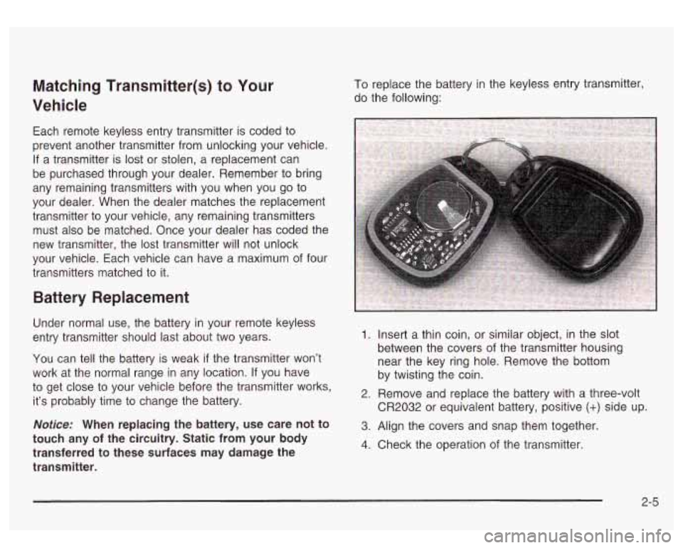
To replace the battery in the keyless entry transmitter,
do the following:
1. Insert a thin coin, or similar object, in the slot
between the covers
of the transmitter housing
near the key ring hole. Remove the bottom
by twisting the coin.
CR2032 or equivalent battery, positive
(+) side up.
2. Remove and replace the battery with a three-volt
3. Align the covers and snap them together.
4. Check the operation of the transmitter.
2-5
Page 97 of 428
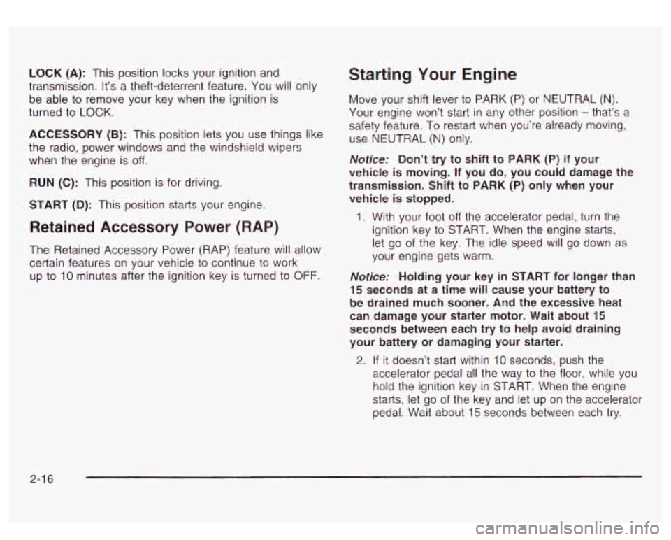
LOCK (A): This position locks your ignition and
transmission. It’s a theft-deterrent feature. You will only
be able to remove your key when the ignition is
turned to
LOCK.
ACCESSORY (B): This position lets you use things like
the radio, power windows and the windshield wipers
when the engine is
off.
RUN (C): This position is for driving.
START
(D): This position starts your engine.
Retained Accessory Power (RAP)
The Retained Accessory Power (RAP) feature will allow
certain features on your vehicle to continue to work
up to
10 minutes after the ignition key is turned to OFF.
Starting Your Engine
Move your shift lever to PARK (P) or NEUTRAL (N).
Your engine won’t start in any other position - that’s a
safety feature. To restart when you’re already moving,
use NEUTRAL (N) only.
Notice: Don’t try to shift to PARK (P) if your
vehicle is moving. If you do, you could damage the
transmission. Shift to PARK (P) only when your
vehicle
is stopped.
1. With your foot off the accelerator pedal, turn the
ignition key to START. When the engine starts,
let go of the key. The idle speed will go down as
your engine gets warm.
Notice: Holding your key in START for longer than
15 seconds at a time will cause your battery to
be drained much sooner. And the excessive heat
can damage your starter motor. Wait about
15
seconds between each try to help avoid draining
your battery or damaging your starter.
2. If it doesn’t start within 10 seconds, push the
accelerator pedal all the way
to the floor, while you
hold the ignition key in START. When the engine
starts, let
go of the key and let up on the accelerator
pedal. Wait about
15 seconds between each try.
2-1 6
Page 117 of 428
Be sure that people and objects are clear of the garage
door or gate operator you are programming. When
programming a garage door, it is advised to park outside
of the garage.
It is recommended that a new battery be installed in
your hand-held transmitter for quicker and more
accurate transmission of the radio frequency.
Your vehicle’s engine should be turned
off while
programming the transmitter. Follow these steps to
program up to three channels:
1. Press and hold down the two outside buttons,
releasing only when the indicator light begins to
flash, after
20 seconds. Do not hold down the
buttons for longer than 30 seconds and do not
repeat this step to program a second and/or third
transmitter to the remaining two HomeLink@ buttons.
2. Position the end of your hand-held transmitter about
1 to 3 inches (3 to 8 cm) away from the HomeLink@
buttons while keeping the indicator light in view.
3. Simultaneously press and hold both the desired
button on HomeLink@ and the hand-held transmitter
button.
Do not release the buttons until Step 4
has been completed.
Some entry gates and garage door openers may
require you to substitute Step 3 with the procedure
noted in “Gate Operator and Canadian
Programming” later in this section.
4. The indicator light will flash slowly at first and then
rapidly after HomeLink@ successfully receives the
frequency signal from the hand-held transmitter.
Release both buttons.
5. Press and hold the newly-trained HomeLink@ button
and observe the indicator light.
If the indicator light stays on constantly,
programming is complete and your device should
activate when the HomeLink@ button is pressed and
released.
To program the remaining two HomeLink@ buttons,
begin with Step
2 under “Programming HomeLink@.”
Do not repeat Step 1 as this will erase all of the
programmed channels.
If the indicator light blinks rapidly for two seconds
and then turns to a constant light, continue with
Steps 6 through
8 following to complete the
programming of a rolling-code equipped device
(most commonly, a garage door opener).
6. At the garage door opener receiver (motor-head
unit) in the garage, locate the “Learn” or “Smart”
button. This can usually be found where the hanging
antenna wire is attached to the motor-head unit.
7. Firmly press and release the “Learn” or “Smart”
button. The name and color of the button may
vary by manufacturer.
You
will have 30 seconds to start Step 8.
2-36
Page 126 of 428
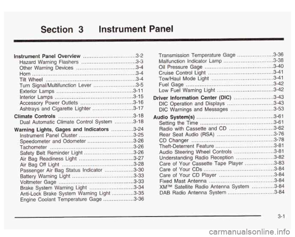
Section 3 Instrument Panel
I~s~Pu~~~IP Panel OWWV~~W ............................... 3.2
Hazard Warning Flashers
................................ 3.3
Other Warning Devices ................................... 3.4
Horn
............................................................. 3.4
Tilt Wheel
..................................................... 3.4
Turn SignaVMultifunction Lever
......................... 3.5
Exterior Lamps
............................................. 3.11
Interior Lamps
.............................................. 3.15
Accessory Power Outlets
............................... 3.16
Ashtrays and Cigarette Lighter
........................ 3.17
Climate Controls
............................................ 3.18
Dual Automatic Climate Control System
........... 3.18
Warning Lights, Gages and Indicators
............. 3.24
Instrument Panel Cluster
................................ 3.25
Speedometer and Odometer
........................... 3.26
Tachometer
................................................ -3-26
Safety Belt Reminder Light
............................. 3.26
Air Bag Readiness Light
................................ 3-27
Passenger Air Bag Status Indicator
................. 3.30
Battery Warning Light
.................................... 3.33
Brake System Warning Light
.......................... 3.34
Anti-Lock Brake System Warning Light
............. 3.35
Air
Bag
Off Light .......................................... 3-28
Voltmeter Gage
............................................ 3-33
Engine Coolant Temperature Gage
..... ..... 3.36 Transmission Temperature
Gage
..................... 3.36
Malfunction Indicator Lamp
............................. 3.38
Oil Pressure Gage
........................................ 3-40
Cruise Control Light
...................................... 3.41
Tow/Haul Mode Light
.................................... 3-41
Fuel Gage
................................................... 3.42
Driver Information Center (DIC)
....................... 3.43
DIC Operation and Displays
........................... 3.43
DIC Warnings and Messages
......................... 3.53
Audio System(s)
............................................. 3.61
Setting the Time
...................... .......... 3.6 1
Radio with Cassette and CD ..... .............. 3.62
Rear Seat Audio (RSA)
............................. 3.76
CD Changer
................................................ 3-78
Theft-Deterrent Feature
................................. -3-81
Audio Steering Wheel Controls
....................... 3.81
Understanding Radio Reception
...................... 3-82
Care of Your Cassette Tape Player
................ -3-83
Care of Your CDs
......................................... 3.84
Care of Your CD Player
................................ 3.84
Fixed Mast Antenna
...................................... 3.84
XMTM Satellite Radio Antenna System
............. 3.84
DAB Radio Antenna System
........................... 3.84
Low Fuel Warning Light
................................. 3-42
Page 141 of 428
Dome Lamps
The dome lamps will come on when you open a door
and the dome override button is
in the out position.
You can also turn the dome lamps on by turning
the thumbwheel, located next to the exterior lamps
control, all the way up. In this position, the dome lamps
will remain on whether the doors are opened or
closed.
*: You can use the dome override button, located
below the exterior lamps control, to set the dome lamps
to come on automatically when the doors are opened,
or to remain
off. To turn the lamps off, press the button
to the
in position. With the button in this position, the
dome lamps will remain
off when the doors are open. To
return the lamps to automatic operation, press the
button again and return the button to the out position.
With the button
in this position, the dome lamps
will come on when you open a door.
Battery Run-Down Protection
This feature shuts off the dome, reading, glove box, and
underhood lamps
if they are left on for more than
10 minutes when the ignition is turned off. The cargo
lamp will shut
off after 20 minutes. This will keep
your battery from running down.
Accessory Power Outlets
With accessory power outlets you can plug in auxiliary
electrical equipment such as a cellular telephone or
other devices designed to operate with vehicle electrical
systems.
Your vehicle is equipped with several accessory power
outlets. The front outlet is located next to the floor
console. Lift up on the door to access the outlet.
The second outlet is located
in the center console. Press
the button on the side
of the console door to access
the outlet. See
Center Console Storage Area on
page 2-39 for more information.
There is also one accessory power outlet located on the
rear of the center console. Lift up on the doors to
access the outlets.
3-1 6
Page 158 of 428
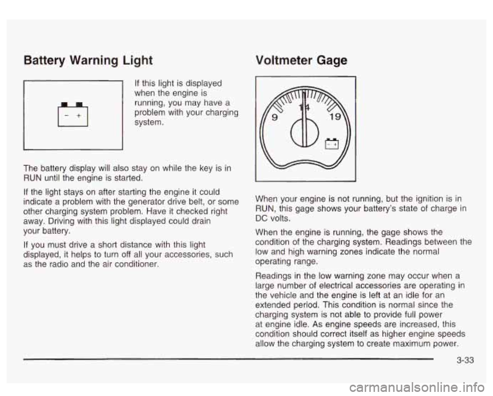
Battery Warning Light Voltmeter Gage
If this light is displayed
when the engine is
running, you may have a
problem with your charging
system.
The battery display will also stay on while the key is in
RUN until the engine is started.
If the light stays on after starting the engine it could
indicate a problem with the generator drive belt, or some
other charging system problem. Have it checked right
away. Driving with this light displayed could drain
your battery.
If you must drive a short distance with this light
displayed, it helps to turn
off all your accessories, such
as the radio and the air conditioner. When your
engine is not running, but the ignition is in
RUN, this gage shows your battery’s state of charge in
DC volts.
When the engine is running, the gage shows the
condition of the charging system. Readings between the
low and high warning zones indicate the normal
operating range.
Readings in the low warning zone may occur when a
large number
of electrical accessories are operating in
the vehicle and the engine is left at an idle for an
extended period. This condition
is normal since the
charging system is not able to provide full power
at engine idle.
As engine speeds are increased, this
condition should correct itself as higher engine speeds
allow the charging system to create maximum power.
3-33
Page 165 of 428
Emissions Inspection and Maintenance
Programs
Some state/provincial and local governments have or
may begin programs to inspect the emission control
equipment on your vehicle. Failure to pass this
inspection could prevent you from getting a vehicle
registration.
Here are some things you need to know to help your
vehicle pass an inspection:
Your vehicle will not pass this inspection
if the Check
Engine light is on or not working properly.
Your vehicle will not pass this inspection
if the OBD
(on-board diagnostic) system determines that critical
emission control systems have not been completely
diagnosed by the system. The vehicle would be
considered not ready for inspection. This can happen
if
you have recently replaced your battery or if your
battery has run down. The diagnostic system is
designed to evaluate critical emission control systems
during normal driving. This may take several days
of routine driving.
If you have done this and your vehicle
still does not pass the inspection for lack of
OBD
system readiness, see your dealer or qualified service
center to prepare the vehicle for inspection.
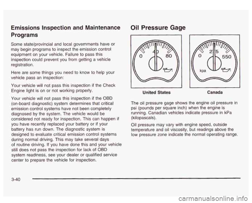
Oil Pressure Gage
I I
United States Canada
The oil pressure gage shows the engine oil pressure in
psi (pounds per square inch) when the engine is
running. Canadian vehicles indicate pressure in kPa
(kilopascals).
Oil pressure may vary with engine speed, outside
temperature and oil viscosity, but readings above the
low pressure zone indicate the normal operating range.
3-40