GREAT WALL HOVER 2006 Service Owners Manual
Manufacturer: GREAT WALL, Model Year: 2006, Model line: HOVER, Model: GREAT WALL HOVER 2006Pages: 425, PDF Size: 26.05 MB
Page 91 of 425
Automatic transmission-15
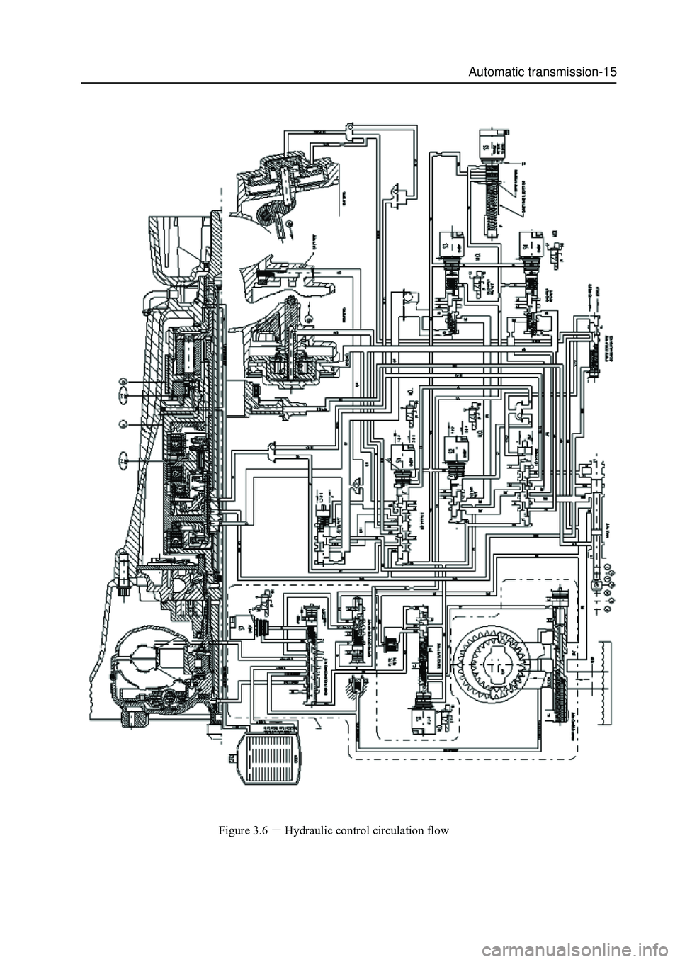
Figure 3.6Hydraulic control circulation flow
Page 92 of 425
Automatic transmission-16
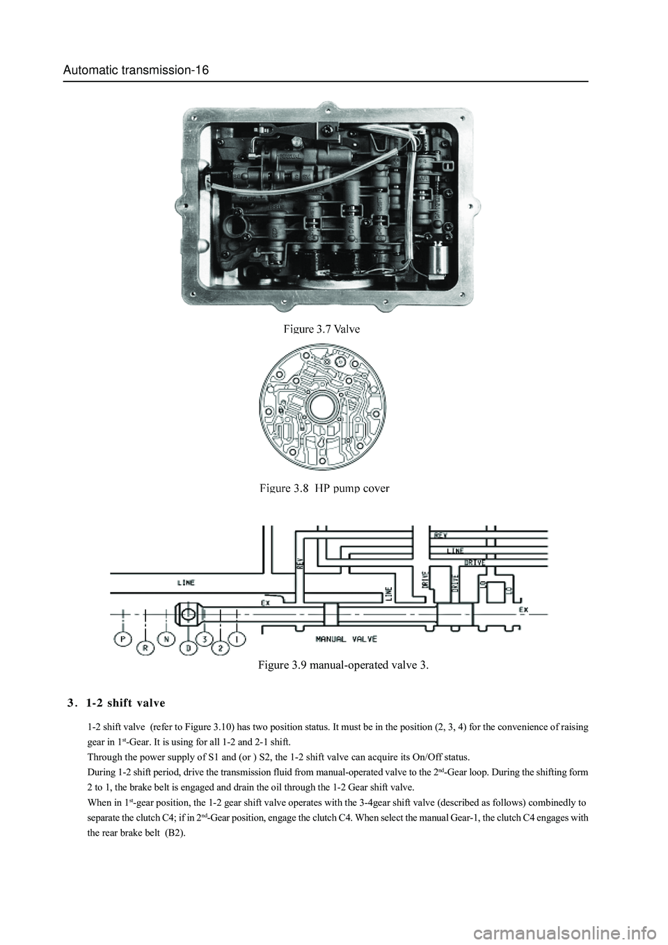
Figure 3.9 manual-operated valve 3.
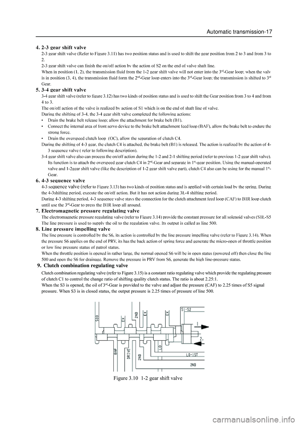
1-2 shift valve (refer to Figure 3.10) has two position status. It must be in the position (2, 3, 4) for the convenience of raising
gear in 1
st-Gear. It is using for all 1-2 and 2-1 shift.
Through the power supply of S1 and (or ) S2, the 1-2 shift valve can acquire its On/Off status.
During 1-2 shift period, drive the transmission fluid from manual-operated valve to the 2
nd-Gear loop. During the shifting form
2 to 1, the brake belt is engaged and drain the oil through the 1-2 Gear shift valve.
When in 1
st-gear position, the 1-2 gear shift valve operates with the 3-4gear shift valve (described as follows) combinedly to
separate the clutch C4; if in 2
nd-Gear position, engage the clutch C4. When select the manual Gear-1, the clutch C4 engages with
the rear brake belt (B2).
31-2 shift valve
Page 93 of 425
Automatic transmission-17
Figure 3.10 1-2 gear shift valve
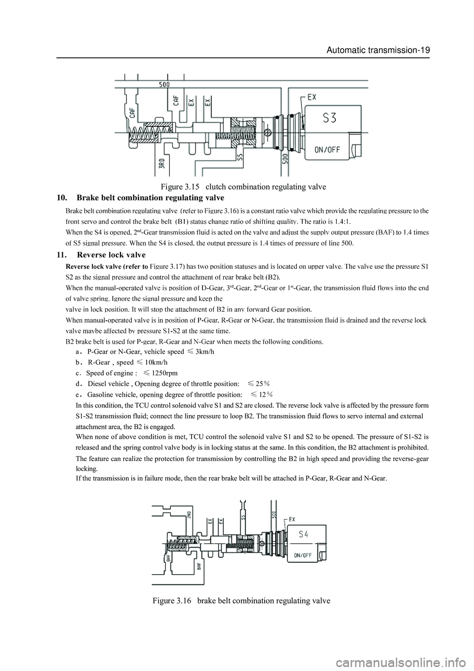
Clutch combination regulating valve (refer to Figure 3.15) is a constant ratio regulating valve which provide the regulating pressure
of clutch C1 to control the change ratio of shifting quality clutch status. The ratio is about 2.25:1.
When the S3 is opened, the oil of 3
rd-Gear is provided to the valve and adjust the pressure (CAF) to 2.25 times of S5 signal
pressure. When S3 is in closed status, the output pressure is 2.25 times of pressure of line 500.
9. Clutch combination regulating valve
Page 94 of 425
Automatic transmission-18
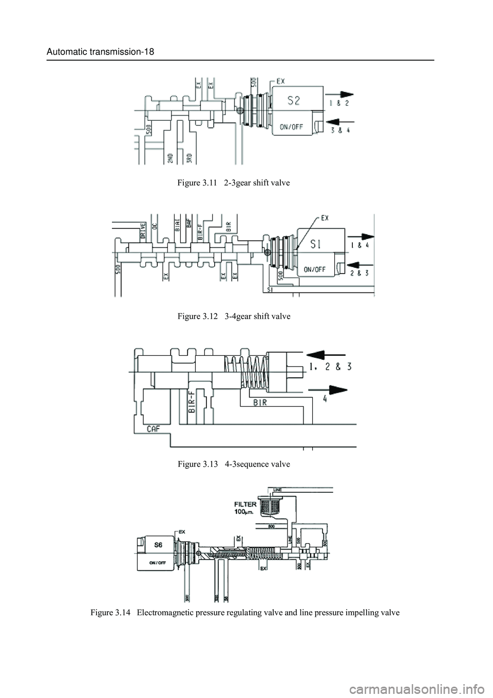
Figure 3.11 2-3gear shift valve
Figure 3.12 3-4gear shift valve
Figure 3.13 4-3sequence valve
Figure 3.14 Electromagnetic pressure regulating valve and line pressure impelling valve
Page 95 of 425
Automatic transmission-19
Figure 3.15 clutch combination regulating valve
10. Brake belt combination regulating valve
aP-Gear or N-Gear, vehicle speed 3km/h
b
R-Gear , speed 10km/h
c
Speed of engine : 1250rpm
d
Diesel vehicle , Opening degree of throttle position: 25
eGasoline vehicle, opening degree of throttle position: 12
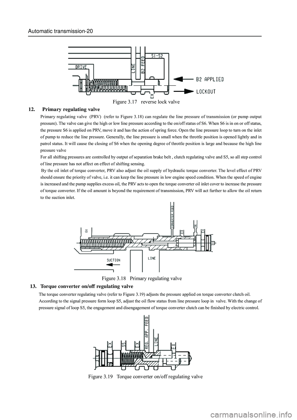
In this condition, the TCU control solenoid valve S1 and S2 are closed. The reverse lock valve is affected by the pressure form
S1-S2 transmission fluid; connect the line pressure to loop B2. The transmission fluid flows to servo internal and external
attachment area, the B2 is engaged.
When none of above condition is met, TCU control the solenoid valve S1 and S2 to be opened. The pressure of S1-S2 is
released and the spring control valve body is in locking status at the same. In this condition, the B2 attachment is prohibited.
The feature can realize the protection for transmission by controlling the B2 in high speed and providing the reverse-gear
locking.
If the transmission is in failure mode, then the rear brake belt will be attached in P-Gear, R-Gear and N-Gear.
Figure 3.16 brake belt combination regulating valve
Page 96 of 425
Automatic transmission-20
Figure 3.17 reverse lock valve
12. Primary regulating valve
Primary regulating valve (PRV) (refer to Figure 3.18) can regulate the line pressure of transmission (or pump output
pressure). The valve can give the high or low line pressure according to the on/off status of S6. When S6 is in on or off status,
the pressure S6 is applied on PRV, move it and has the action of spring force. Open the line pressure loop to turn on the inlet
of pump to reduce the line pressure. Generally, the line pressure is small when the throttle position is opened lightly and in
patrol status. It will cause the closing of S6 when the opening degree of throttle position is large and because the high line
pressure valve
For all shifting pressures are controlled by output of separation brake belt , clutch regulating valve and S5, so all step control
of line pressure has not affect on effect of shifting sensing.
By the oil inlet of torque converter, PRV also adjust the oil supply of hydraulic torque converter. The level effect of PRV
should ensure the priority of valve, i.e. it can keep the line pressure in low engine speed condition. When the speed of engine
is increased and the pump supplies excess oil, the PRV acts to open the torque converter oil inlet cover to increase the pressure
of torque converter. If the oil amount is beyond the requirement of transmission, PRV will act further to allow the oil return
to the suction inlet.
Figure 3.18 Primary regulating valve
Figure 3.19 Torque converter on/off regulating valve
The torque converter regulating valve (refer to Figure 3.19) adjusts the pressure applied on torque converter clutch oil.
According to the signal pressure form loop S5, adjust the oil flow status from line pressure loop in valve. With the change of
pressure signal of loop S5, the engagement and disengagement of torque converter clutch can be finished by electric control.
13. Torque converter on/off regulating valve
Page 97 of 425
Automatic transmission-21
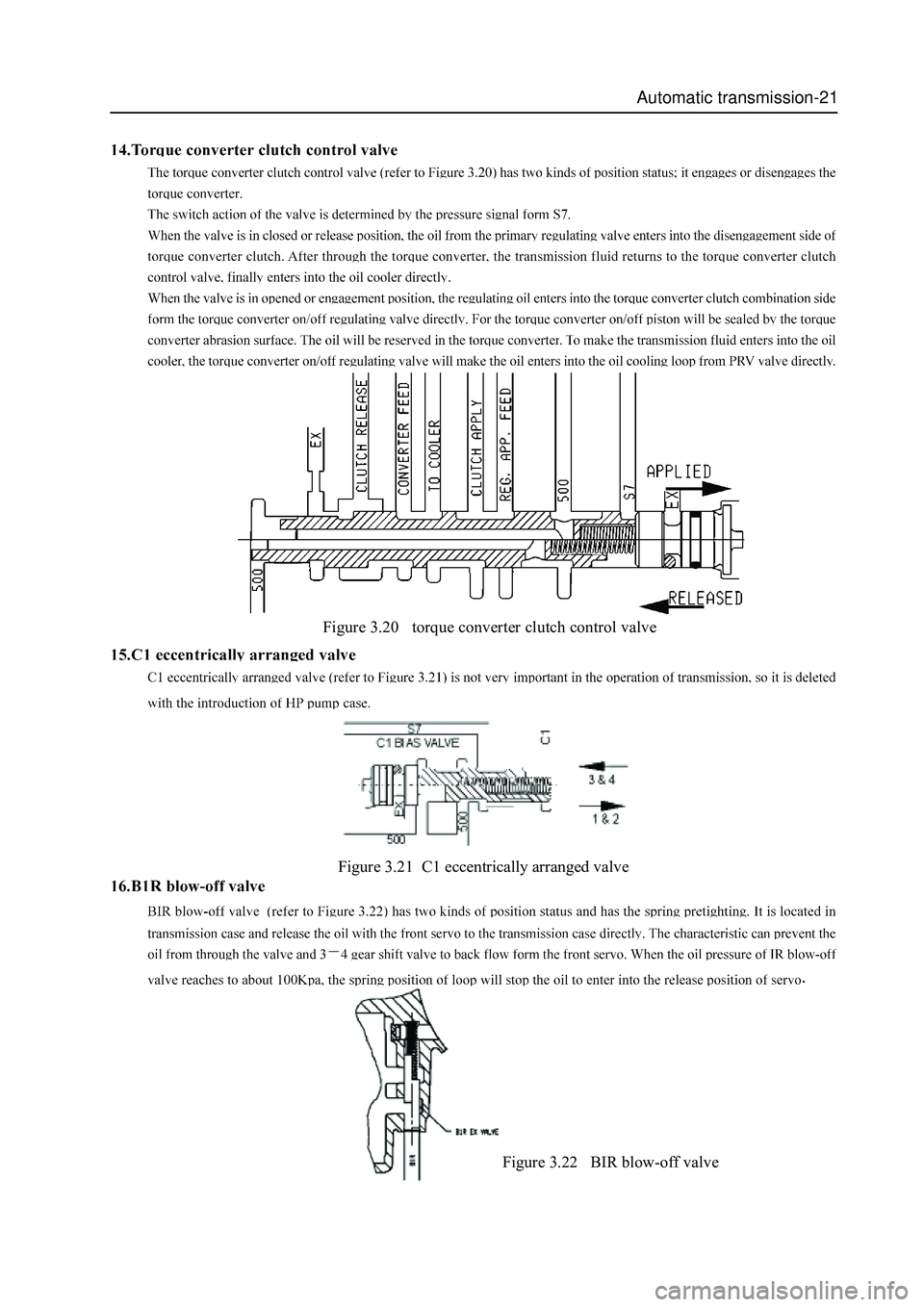
Figure 3.20 torque converter clutch control valve
Figure 3.21 C1 eccentrically arranged valve
.
Figure 3.22 BIR blow-off valve
Page 98 of 425
Automatic transmission-22
Power transmission system
The power transmission system includes:
Torque converter equipped with single lock clutch.
4 multi-plate clutch assemblies
2 brake belts
2 one-way clutches
Planetary gear assembly
parking mechanism
A traditional planetary gear assembly composed by six pinions is used in four-speed transmission. It realizes the 4 Gear power
transmission through the drive gear bracket.
So, the cross arrangement is the main arranging method. In the box, there are four subassemblies, shown as follows:
Gear bank central support
C1-C2-C3-clutch C4 subassembly
Pump assembly
Valve assembly
One piece or one set of optional shim is located between the input shaft flange and center of stator support shaft axle of and used
to control the end flotation of transmission. The structure arrangement allows the inspection for the subassembly during the
product manufacturing period.
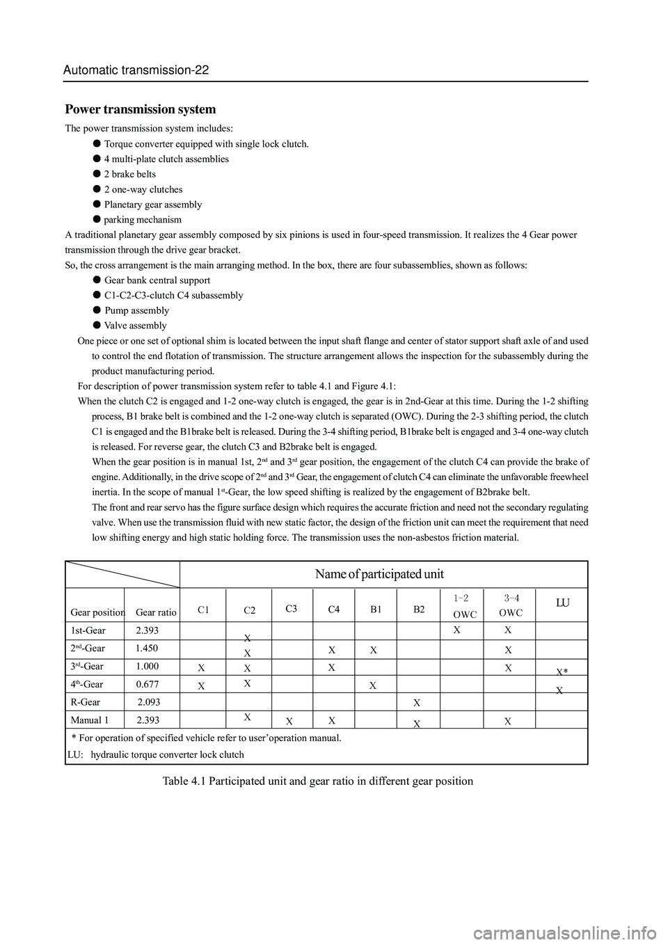
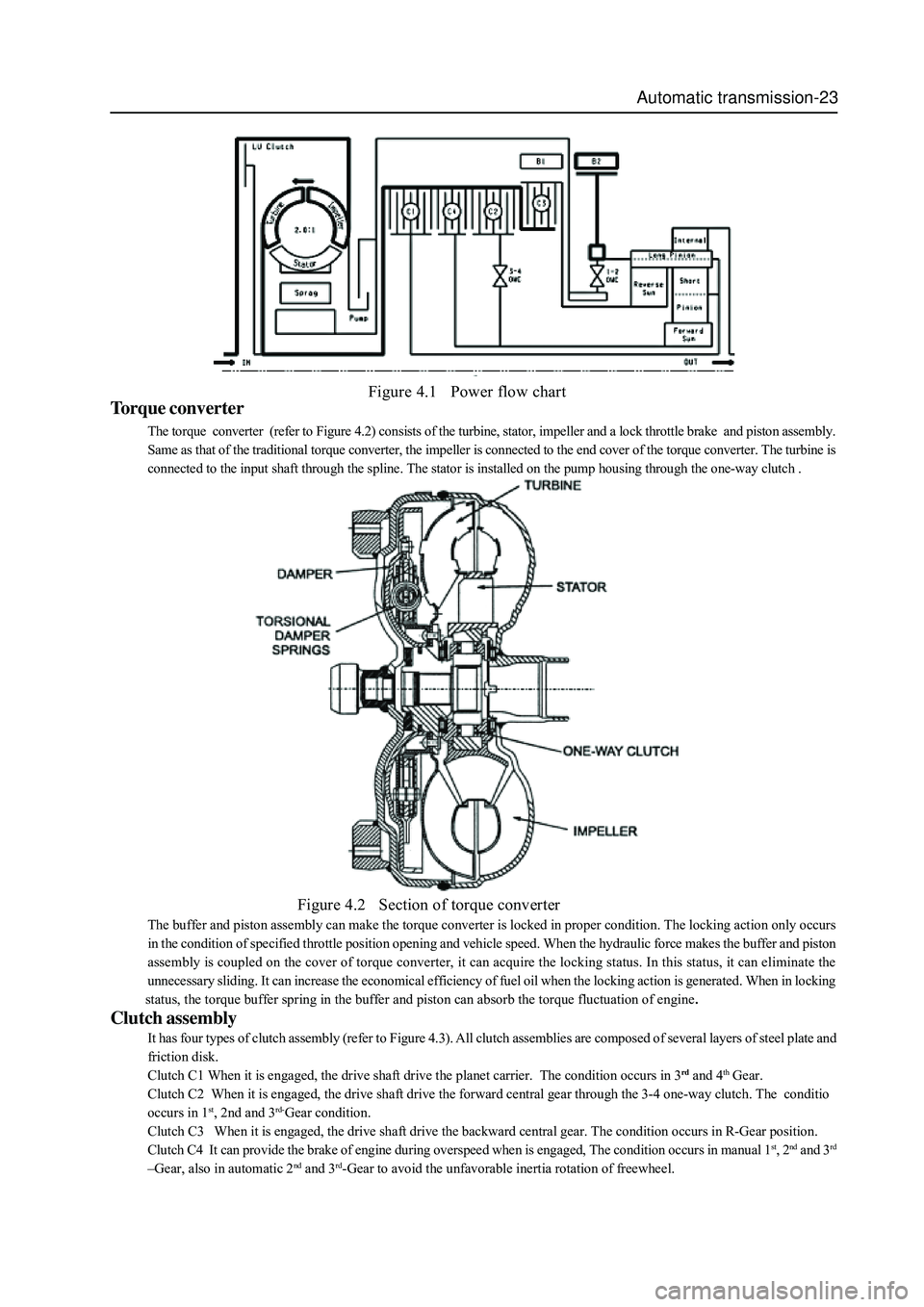
For description of power transmission system refer to table 4.1 and Figure 4.1:
When the clutch C2 is engaged and 1-2 one-way clutch is engaged, the gear is in 2nd-Gear at this time. During the 1-2 shifting
process, B1 brake belt is combined and the 1-2 one-way clutch is separated (OWC). During the 2-3 shifting period, the clutch
C1 is engaged and the B1brake belt is released. During the 3-4 shifting period, B1brake belt is engaged and 3-4 one-way clutch
is released. For reverse gear, the clutch C3 and B2brake belt is engaged.
When the gear position is in manual 1st, 2
nd and 3rd gear position, the engagement of the clutch C4 can provide the brake of
engine. Additionally, in the drive scope of 2
nd and 3rd Gear, the engagement of clutch C4 can eliminate the unfavorable freewheel
inertia. In the scope of manual 1
st-Gear, the low speed shifting is realized by the engagement of B2brake belt.
The front and rear servo has the figure surface design which requires the accurate friction and need not the secondary regulating
valve. When use the transmission fluid with new static factor, the design of the friction unit can meet the requirement that need
low shifting energy and high static holding force. The transmission uses the non-asbestos friction material.
LUGear position Gear ratio
1st-Gear 2.393
2
nd-Gear 1.450
3
rd-Gear 1.000
4
th-Gear 0.677
R-Gear 2.093
Manual 1 2.393
C3C4 B1 B2
Name of participated unit
* For operation of specified vehicle refer to user’operation manual.
LU: hydraulic torque converter lock clutch
Table 4.1 Participated unit and gear ratio in different gear position
Page 99 of 425
Automatic transmission-23
Figure 4.1 Power flow chart
Torque converter
The torque converter (refer to Figure 4.2) consists of the turbine, stator, impeller and a lock throttle brake and piston assembly.
Same as that of the traditional torque converter, the impeller is connected to the end cover of the torque converter. The turbine is
connected to the input shaft through the spline. The stator is installed on the pump housing through the one-way clutch .
Figure 4.2 Section of torque converter
The buffer and piston assembly can make the torque converter is locked in proper condition. The locking action only occurs
in the condition of specified throttle position opening and vehicle speed. When the hydraulic force makes the buffer and piston
assembly is coupled on the cover of torque converter, it can acquire the locking status. In this status, it can eliminate the
unnecessary sliding. It can increase the economical efficiency of fuel oil when the locking action is generated. When in locking
status, the torque buffer spring in the buffer and piston can absorb the torque fluctuation of engine
.
Clutch assembly
It has four types of clutch assembly (refer to Figure 4.3). All clutch assemblies are composed of several layers of steel plate and
friction disk.
Clutch C1 When it is engaged, the drive shaft drive the planet carrier. The condition occurs in 3
rd and 4th Gear.
Clutch C2 When it is engaged, the drive shaft drive the forward central gear through the 3-4 one-way clutch. The conditio
occurs in 1
st, 2nd and 3rd-Gear condition.
Clutch C3 When it is engaged, the drive shaft drive the backward central gear. The condition occurs in R-Gear position.
Clutch C4 It can provide the brake of engine during overspeed when is engaged, The condition occurs in manual 1
st, 2nd and 3rd
–Gear, also in automatic 2nd and 3rd-Gear to avoid the unfavorable inertia rotation of freewheel.
Page 100 of 425
Automatic transmission-24
Front servo and brake belt Rear servo and brake belt
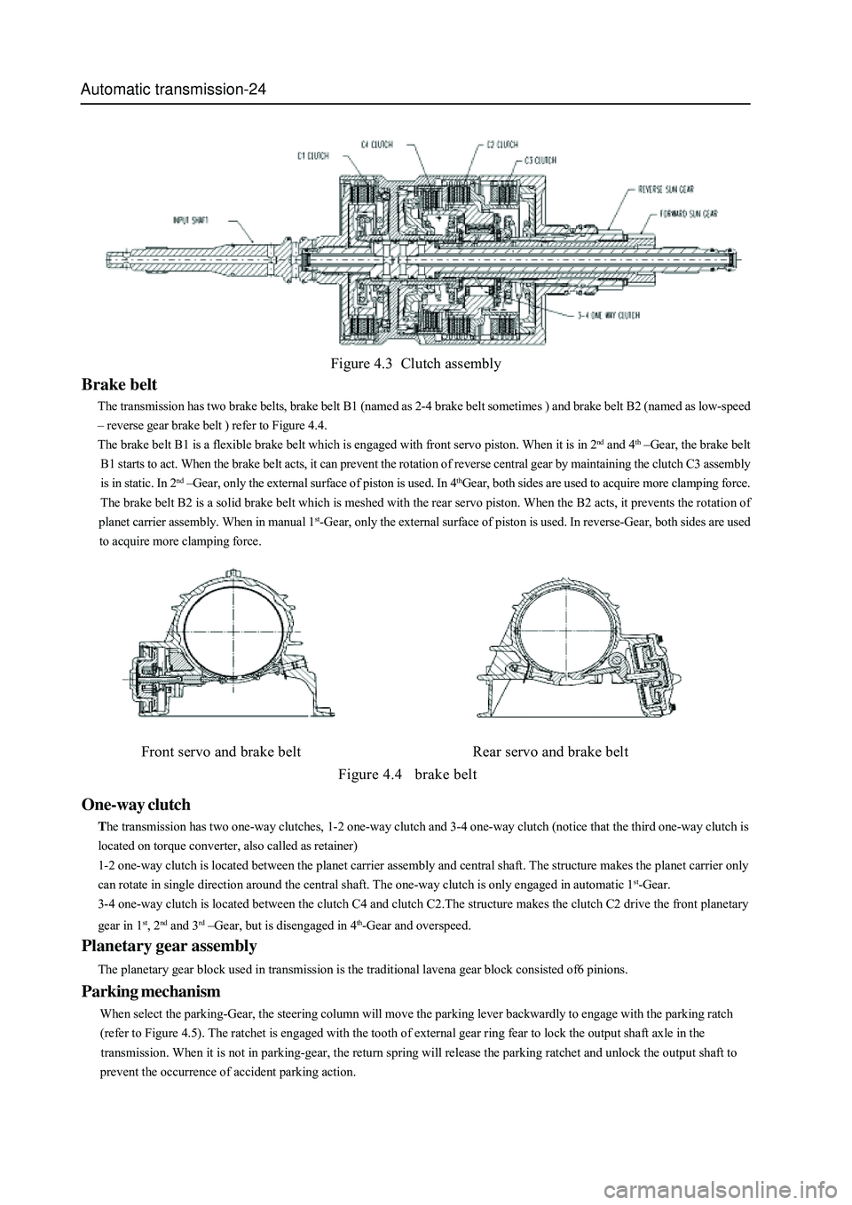
Figure 4.4 brake belt
One-way clutch
The transmission has two one-way clutches, 1-2 one-way clutch and 3-4 one-way clutch (notice that the third one-way clutch is
located on torque converter, also called as retainer)
1-2 one-way clutch is located between the planet carrier assembly and central shaft. The structure makes the planet carrier only
can rotate in single direction around the central shaft. The one-way clutch is only engaged in automatic 1
st-Gear.
3-4 one-way clutch is located between the clutch C4 and clutch C2.The structure makes the clutch C2 drive the front planetary
gear in 1
st, 2nd and 3rd –Gear, but is disengaged in 4th-Gear and overspeed.
Planetary gear assembly
The planetary gear block used in transmission is the traditional lavena gear block consisted of6 pinions.
Parking mechanism
When select the parking-Gear, the steering column will move the parking lever backwardly to engage with the parking ratch
(refer to Figure 4.5). The ratchet is engaged with the tooth of external gear ring fear to lock the output shaft axle in the
transmission. When it is not in parking-gear, the return spring will release the parking ratchet and unlock the output shaft to
prevent the occurrence of accident parking action.
Figure 4.3 Clutch assembly
Brake belt
The transmission has two brake belts, brake belt B1 (named as 2-4 brake belt sometimes ) and brake belt B2 (named as low-speed
– reverse gear brake belt ) refer to Figure 4.4.
The brake belt B1 is a flexible brake belt which is engaged with front servo piston. When it is in 2
nd and 4th –Gear, the brake belt
B1 starts to act. When the brake belt acts, it can prevent the rotation of reverse central gear by maintaining the clutch C3 assembly
is in static. In 2
nd –Gear, only the external surface of piston is used. In 4thGear, both sides are used to acquire more clamping force.
The brake belt B2 is a solid brake belt which is meshed with the rear servo piston. When the B2 acts, it prevents the rotation of
planet carrier assembly. When in manual 1
st-Gear, only the external surface of piston is used. In reverse-Gear, both sides are used
to acquire more clamping force.