GREAT WALL HOVER 2006 Service Repair Manual
Manufacturer: GREAT WALL, Model Year: 2006, Model line: HOVER, Model: GREAT WALL HOVER 2006Pages: 425, PDF Size: 26.05 MB
Page 131 of 425
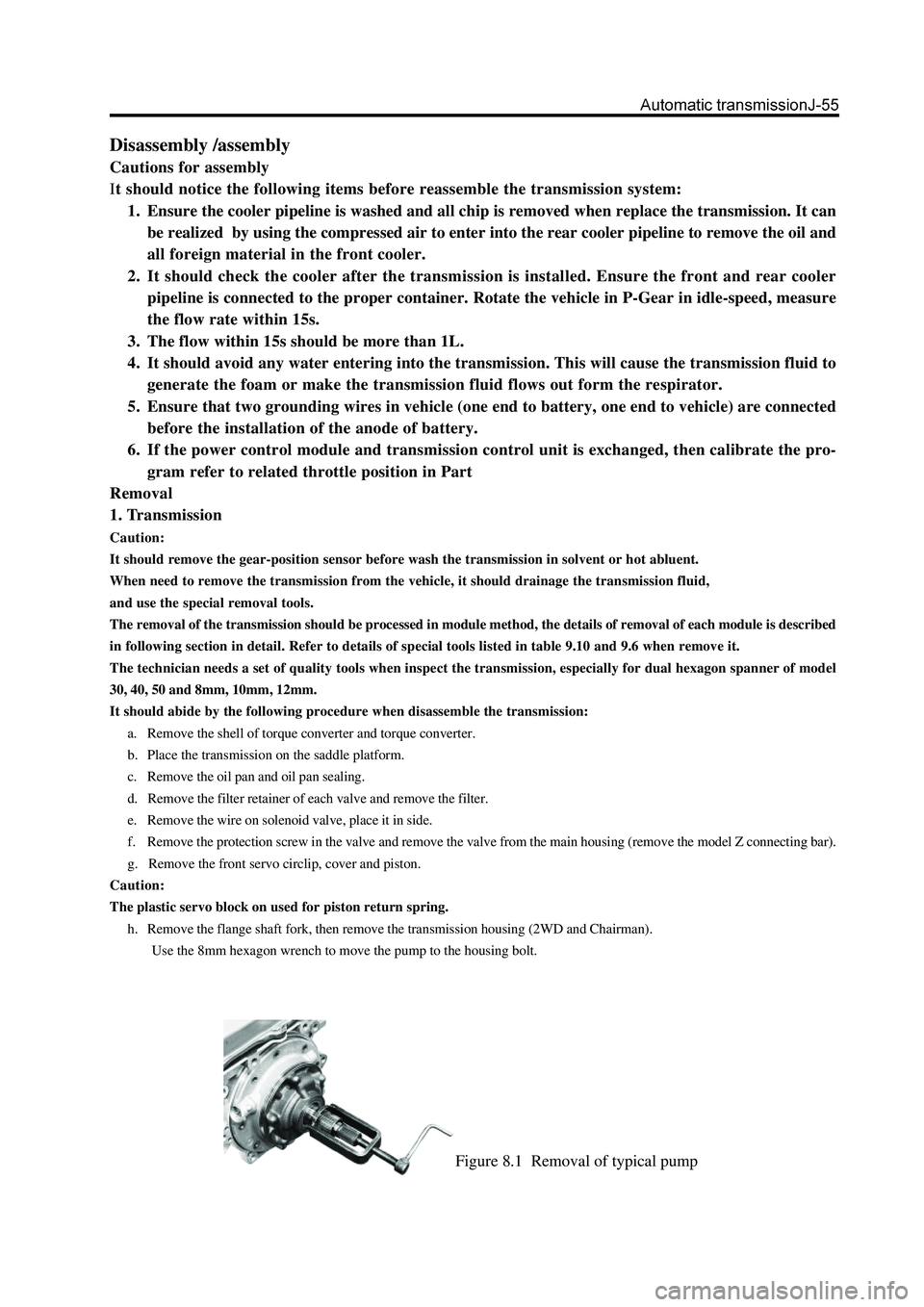
Figure 8.1 Removal of typical pump
Disassembly /assembly
Cautions for assembly
It should notice the following items before reassemble the transmission system:
1. Ensure the cooler pipeline is washed and all chip is removed when replace the transmission. It can
be realized by using the compressed air to enter into the rear cooler pipeline to remove the oil and
all foreign material in the front cooler.
2. It should check the cooler after the transmission is installed. Ensure the front and rear cooler
pipeline is connected to the proper container. Rotate the vehicle in P-Gear in idle-speed, measure
the flow rate within 15s.
3. The flow within 15s should be more than 1L.
4. It should avoid any water entering into the transmission. This will cause the transmission fluid to
generate the foam or make the transmission fluid flows out form the respirator.
5. Ensure that two grounding wires in vehicle (one end to battery, one end to vehicle) are connected
before the installation of the anode of battery.
6. If the power control module and transmission control unit is exchanged, then calibrate the pro-
gram refer to related throttle position in Part
Removal
1. Transmission
Caution:
It should remove the gear-position sensor before wash the transmission in solvent or hot abluent.
When need to remove the transmission from the vehicle, it should drainage the transmission fluid,
and use the special removal tools.
The removal of the transmission should be processed in module method, the details of removal of each module is described
in following section in detail. Refer to details of special tools listed in table 9.10 and 9.6 when remove it.
The technician needs a set of quality tools when inspect the transmission, especially for dual hexagon spanner of model
30, 40, 50 and 8mm, 10mm, 12mm.
It should abide by the following procedure when disassemble the transmission:
a. Remove the shell of torque converter and torque converter.
b. Place the transmission on the saddle platform.
c. Remove the oil pan and oil pan sealing.
d. Remove the filter retainer of each valve and remove the filter.
e. Remove the wire on solenoid valve, place it in side.
f. Remove the protection screw in the valve and remove the valve from the main housing (remove the model Z connecting bar).
g. Remove the front servo circlip, cover and piston.
Caution:
The plastic servo block on used for piston return spring.
h. Remove the flange shaft fork, then remove the transmission housing (2WD and Chairman).
Use the 8mm hexagon wrench to move the pump to the housing bolt.
Page 132 of 425

Caution:
Do not take out the central support by knocking the output shaft , otherwise, it will damage the surface of thrust bearing
permanently
o. Remove the central support, 1-2 one-way clutch and planetary gear block.
p. Use the T40 special tools to remove the parking lever cum disc.
q. Remove the rear brake belt support and rear brake belt.
r. Remove the output shaft assembly.
2. Transmission case
It should follow the following procedure when remove the transmission:
a. Use the tools to take out the fixed pin from one side of cross shaft gear sensor (2WD and 4WD mode).
b. Remove the gear sensor from the case. Use the special tools to take out the cross shaft seal.
c. Take out the circlip from the cross shaft. Pull up the cross shaft and take out the drive pin from the sector gear-position
selection plate.
d. Use the tools, press down the cross-shaft pin and take out the shaft , reset spring and bolt from the housing. Refer to Figure
8.3.
Figure 8.3 Installation and disassembly of cross-axle pinFigure 8.2 central support retainer
i. Use the pump remover to remove the pump, refer to Figure 8.1.
g. Remove the input shaft , front clutch cylinder and overspeed –Gear shaft as an integral. Take it out from the front of housing.
k. Remove the clutch C3 cylinder and central gear .
l. Remove the brake belt support and brake belt.
m. Use the 50 special tools to remove two central support connecting bolts.
n. Remove the central support retainer, refer to Figure 8.2.
Page 133 of 425

e. Take out the manual-operated valve operating lever and parking operating lever.
f. Take out the 10 pin socket connector form the wire bunch bracket adjacent gear sensor.
g. Press down the raised part of 10-pin plug and take out the 10-pin connecting plug from the box.
h. Separate the NO.7 solenoid valve wire bunch form the front end of housing.
i. Remove the brake bar pivot, brake shaft and spring.
j. Remove the shaft and rear servo operating lever.
k. Remove the rear servo cover and piston assembly.
l. Remove the BIR circlip, valve and spring.
m. Remove two brake belt adjusting shims.
n. Check the output shaft bush in box, replace it if necessary.
o. Check the cooler pipeline, replace it if necessary.
p. Check the box for damage.
Caution:
It must not remove the operating lever of parking gear in normal condition.
q. It needs to remove the P-Gear operating lever: take out the circlip from the pivot, knock the external of shaft until it can move
freely in box. Then use a width and thin object to table out the bolt form the box, operating lever and spring.
3. Front clutch cylinder
When take out the front clutch cylinder, please refer to Figure 8.4. The procedure is shown as follows:
Figure 8.4 Assembly of front clutch cylinder
a. Place the assembly on a level surface.
b. Remove the thrust bearing and adjusting shim from the input shaft .
c. Remove the retainer and input shaft form the front end of clutch .
d. Remove the overspeed gear shaft and clutch C1 hub assembly from the clutch cylinder.
e. Take out the clutch disk C1 form the cylinder.
f. Take out the retainer which fix the clutch C3 hub on the rear end of clutch cylinder, then take out the hub.
g. Take out the C2\clutch C4 hub assembly and remove the thrust bearing form the C4 hub.
h. Take out the clutch C2 disc.
i. Reverse the clutch cylinder and take out the clutch C4 sleeve, clutch disk and two wave washers. The 3-4 one-way clutches is
located between the C2 and clutch C4 hub. The other wheel axle can be taken out by rotating a wheel axle in clockwise.
j. Remove the thrust block form the clutch C4 cylinder hub.
Caution
Ensure the spring keeping device does not be clamped in the spring groove and all spring pressure is released.
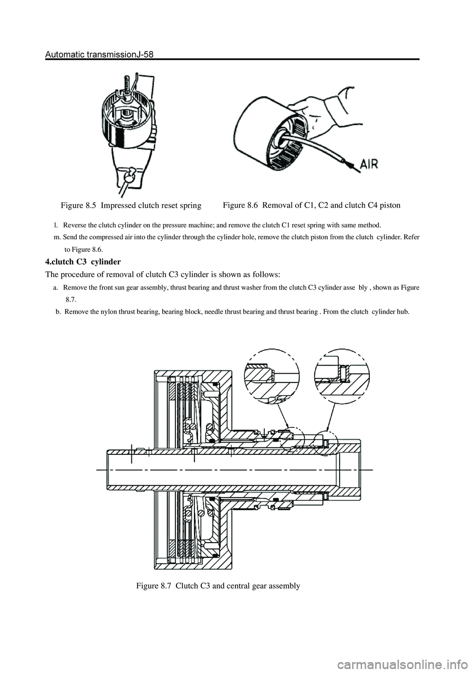
k. Put end surface of C2\clutch C4 upwardly, connect the clutch cylinder with the tools. Pressed down the piston reset spring,
take out the spring fixing retainer (Refer to Figure 8.5). Remove the tools and take out the ring spring, fixing part and spring.
Page 134 of 425
l. Reverse the clutch cylinder on the pressure machine; and remove the clutch C1 reset spring with same method.
m. Send the compressed air into the cylinder through the cylinder hole, remove the clutch piston from the clutch cylinder. Refer
to Figure 8.6.
4.clutch C3 cylinder
The procedure of removal of clutch C3 cylinder is shown as follows:
a. Remove the front sun gear assembly, thrust bearing and thrust washer from the clutch C3 cylinder asse bly , shown as Figure
8.7.
b. Remove the nylon thrust bearing, bearing block, needle thrust bearing and thrust bearing . From the clutch cylinder hub.
Figure 8.5 Impressed clutch reset spring
Figure 8.7 Clutch C3 and central gear assemblyFigure 8.6 Removal of C1, C2 and clutch C4 piston
Page 135 of 425
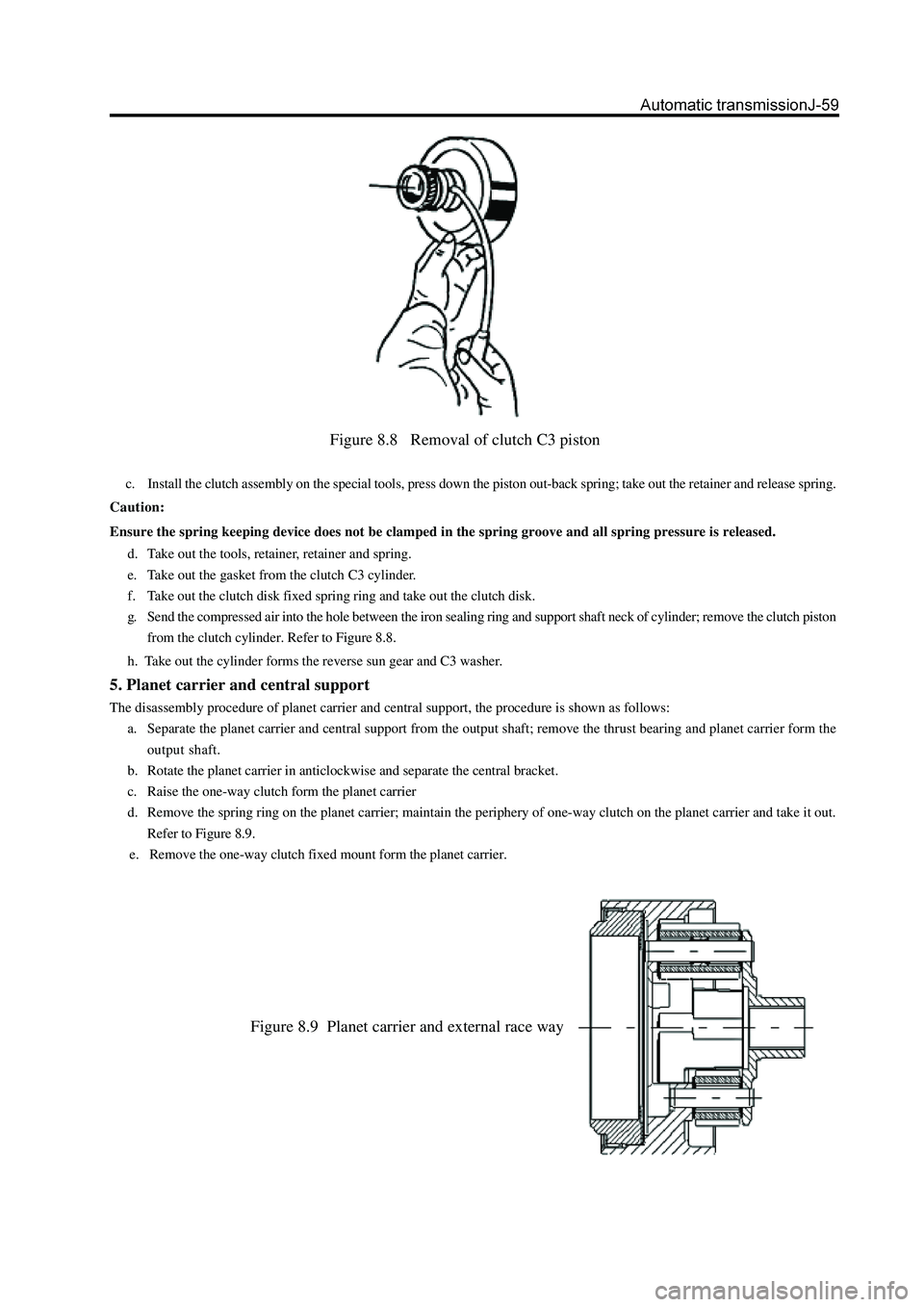
Figure 8.8 Removal of clutch C3 piston
c. Install the clutch assembly on the special tools, press down the piston out-back spring; take out the retainer and release spring.
Caution:
Ensure the spring keeping device does not be clamped in the spring groove and all spring pressure is released.
d. Take out the tools, retainer, retainer and spring.
e. Take out the gasket from the clutch C3 cylinder.
f. Take out the clutch disk fixed spring ring and take out the clutch disk.
g. Send the compressed air into the hole between the iron sealing ring and support shaft neck of cylinder; remove the clutch piston
from the clutch cylinder. Refer to Figure 8.8.
h. Take out the cylinder forms the reverse sun gear and C3 washer.
5. Planet carrier and central support
The disassembly procedure of planet carrier and central support, the procedure is shown as follows:
a. Separate the planet carrier and central support from the output shaft; remove the thrust bearing and planet carrier form the
output shaft.
b. Rotate the planet carrier in anticlockwise and separate the central bracket.
c. Raise the one-way clutch form the planet carrier
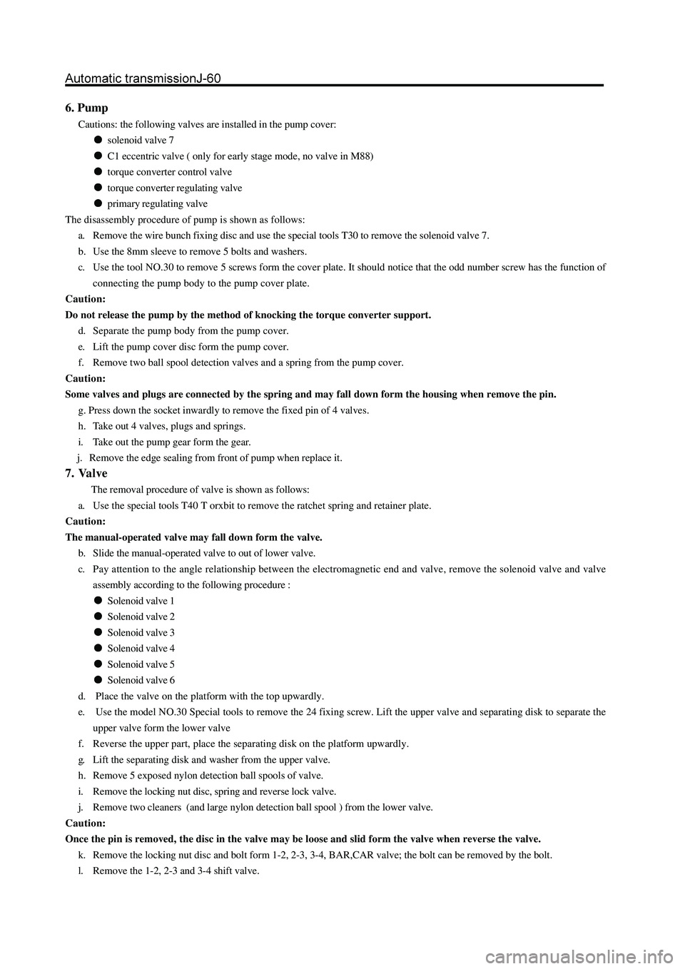
d. Remove the spring ring on the planet carrier; maintain the periphery of one-way clutch on the planet carrier and take it out.
Refer to Figure 8.9.
e. Remove the one-way clutch fixed mount form the planet carrier.
Figure 8.9 Planet carrier and external race way
Page 136 of 425
6. Pump
Cautions: the following valves are installed in the pump cover:
solenoid valve 7
C1 eccentric valve ( only for early stage mode, no valve in M88)
torque converter control valve
torque converter regulating valve
primary regulating valve
The disassembly procedure of pump is shown as follows:
a. Remove the wire bunch fixing disc and use the special tools T30 to remove the solenoid valve 7.
b. Use the 8mm sleeve to remove 5 bolts and washers.
c. Use the tool NO.30 to remove 5 screws form the cover plate. It should notice that the odd number screw has the function of
connecting the pump body to the pump cover plate.
Caution:
Do not release the pump by the method of knocking the torque converter support.
d. Separate the pump body from the pump cover.
e. Lift the pump cover disc form the pump cover.
f. Remove two ball spool detection valves and a spring from the pump cover.
Caution:
Some valves and plugs are connected by the spring and may fall down form the housing when remove the pin.
g. Press down the socket inwardly to remove the fixed pin of 4 valves.
h. Take out 4 valves, plugs and springs.
i. Take out the pump gear form the gear.
j. Remove the edge sealing from front of pump when replace it.
7. Valve
The removal procedure of valve is shown as follows:
a. Use the special tools T40 T orxbit to remove the ratchet spring and retainer plate.
Caution:
The manual-operated valve may fall down form the valve.
b. Slide the manual-operated valve to out of lower valve.
c. Pay attention to the angle relationship between the electromagnetic end and valve, remove the solenoid valve and valve
assembly according to the following procedure :
Solenoid valve 1
Solenoid valve 2
Solenoid valve 3
Solenoid valve 4
Solenoid valve 5
Solenoid valve 6
d. Place the valve on the platform with the top upwardly.
e. Use the model NO.30 Special tools to remove the 24 fixing screw. Lift the upper valve and separating disk to separate the
upper valve form the lower valve
f. Reverse the upper part, place the separating disk on the platform upwardly.
g. Lift the separating disk and washer from the upper valve.
h. Remove 5 exposed nylon detection ball spools of valve.
i. Remove the locking nut disc, spring and reverse lock valve.
j. Remove two cleaners (and large nylon detection ball spool ) from the lower valve.
Caution:
Once the pin is removed, the disc in the valve may be loose and slid form the valve when reverse the valve.
k. Remove the locking nut disc and bolt form 1-2, 2-3, 3-4, BAR,CAR valve; the bolt can be removed by the bolt.
l. Remove the 1-2, 2-3 and 3-4 shift valve.
Page 137 of 425
Caution:
Some valves are pulled by the spring and may fall down form the valve.
m. Press down the plug of 4-3 sequence valve and take out the locking nut disc.
n. Take out the plug, valve and spring.
o. Press down the solenoid valve 5 gate. Remove the fixed pin, valve and spring.
Caution:
The valve is pulled by the spring and may fall down form the valve.
p . Press down the line pressure blow-off valve , then remove the fixed pin, disc (if proper) spring and valve.
q. Take out the roller pin and remove the spring and ball spool detection valve adjacent BAR.
Assembly
The transmission is assembled in the method of module. The detailed assembly process of each module is described in the
following chapter in detail.
Refer to Table 8.1 (end of section 8.3) for the description of used torque specification. The Table 9.10 in section 9.6 describes
the necessary special tools for assembly.
The technician also needs to select the quality Torx tools, especially for the two-screw socket wrench with code of 40, 50,
8mm,10mm and 12mm to detect the transmission completely.
1.Transmission
Caution:
Ensure the BIR retainer is proper for the case (otherwise, the valve will damage the separation disk).
Ensure the E clip is installed on the cross shaft.
Ensure all parts of parking machine can operate normally.
The assembly procedure of transmission is shown as follows:
a. Place the upper transmission on the platform upwardly and place it on the transmission bracket.
b. Install all accessories, bolts and bleed devices. Paint the sealant on the sealing place. Tighten all components according
to the specification. Ensure the cleanness of all bleed devices. Ensure the rear oil filling nozzle of housing is correct and
without blocking material. Refer to Figure 8.19.
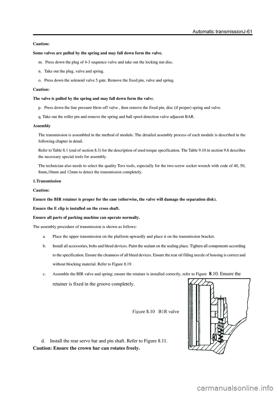
c. Assemble the BIR valve and spring; ensure the retainer is installed correctly, refer to Figure
8.10. Ensure the
retainer is fixed in the groove completely.
d. Install the rear servo bar and pin shaft. Refer to Figure 8.11.
Caution: Ensure the crown bar can rotates freely.
Page 138 of 425

Figure 8.11 Rear servo barCaution:
Pay attention to do not coat the sealant between the bolt and crown bar.
e. Install the parking operating lever (as Figure 8.12), including the return spring and shaft pin. Coat the external end of shaft pin
with small sealant.
f. Use the circlip to protect the shaft pin. Pay attention to ensure the operating lever can rotate around the shaft pin freely and
the spring can make the parking operating lever returns to the correct position.
g. Install the parking brake lever pin and spring. Refer to Figure 8.13.Caution: ensure the rake lever can rotate freely.
h. Connect the parking brake lever to the manual-operated valve connecting rod. Shown as Figure 8.14. Ensure the spring and cam
axle ring are installed on the connecting rod fixedly.
i. Check the cam axle ring for smooth sliding on rod.
j. Install the cross shaft in the box in reverse direction of Gear-position sensor, then install the concussion spring on the shaft.Figure 8.12 Parking operating lever
Figure 8.13 Typical parking brake shaft pin and spring
Figure 8.14 Parking lever and manual shaft
Page 139 of 425
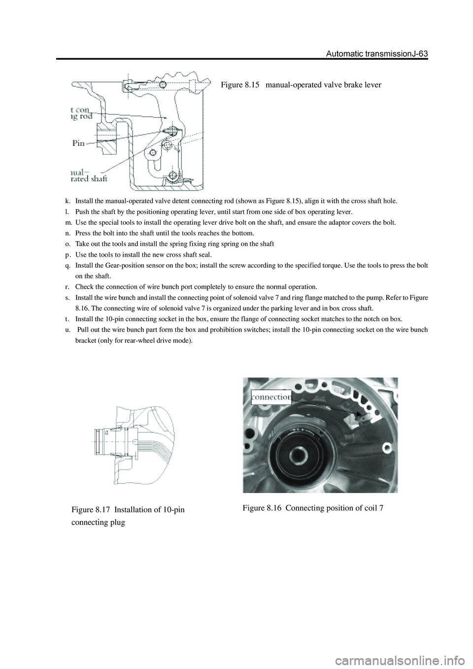
Figure 8.15 manual-operated valve brake lever
k. Install the manual-operated valve detent connecting rod (shown as Figure 8.15), align it with the cross shaft hole.
l. Push the shaft by the positioning operating lever, until start from one side of box operating lever.
m. Use the special tools to install the operating lever drive bolt on the shaft, and ensure the adaptor covers the bolt.
n. Press the bolt into the shaft until the tools reaches the bottom.
o. Take out the tools and install the spring fixing ring spring on the shaft
p . Use the tools to install the new cross shaft seal.
q. Install the Gear-position sensor on the box; install the screw according to the specified torque. Use the tools to press the bolt
on the shaft.
r. Check the connection of wire bunch port completely to ensure the normal operation.
s. Install the wire bunch and install the connecting point of solenoid valve 7 and ring flange matched to the pump. Refer to Figure
8.16. The connecting wire of solenoid valve 7 is organized under the parking lever and in box cross shaft.
t . Install the 10-pin connecting socket in the box, ensure the flange of connecting socket matches to the notch on box.
u. Pull out the wire bunch part form the box and prohibition switches; install the 10-pin connecting socket on the wire bunch
bracket (only for rear-wheel drive mode).
Figure 8.16 Connecting position of coil 7Figure 8.17 Installation of 10-pin
connecting plug
Page 140 of 425
2.output shaft and gear assembly
The assembly procedure of output shaft and gear assembly (Refer to Figure 8.19),is shown as follows:
a. Check the output shaft bush for damage, replace it if necessary.
b. Check the parking detent on the ring gear for damage ; replace it if necessary.
c. Check the sealing ring groove for damage.
d. Use the automatic transmission liquid to lubricate the gasket.
e. Place the scarfing notch upwardly and install the sealing ring on the output shaft.
f. If has been removed., it should use the ring spring for reinforcement when install the ring gear on the output shaft. Ensure the
ring spring is fixed in the groove.
g. Use the Vaseline oil for lubrication; install the thrust bearing assembly NO.10 on the output shaft.
h. It should be carefully when install the output shaft on the box to avoid the damage of sealing ring.
3. Rear brake belt assembly
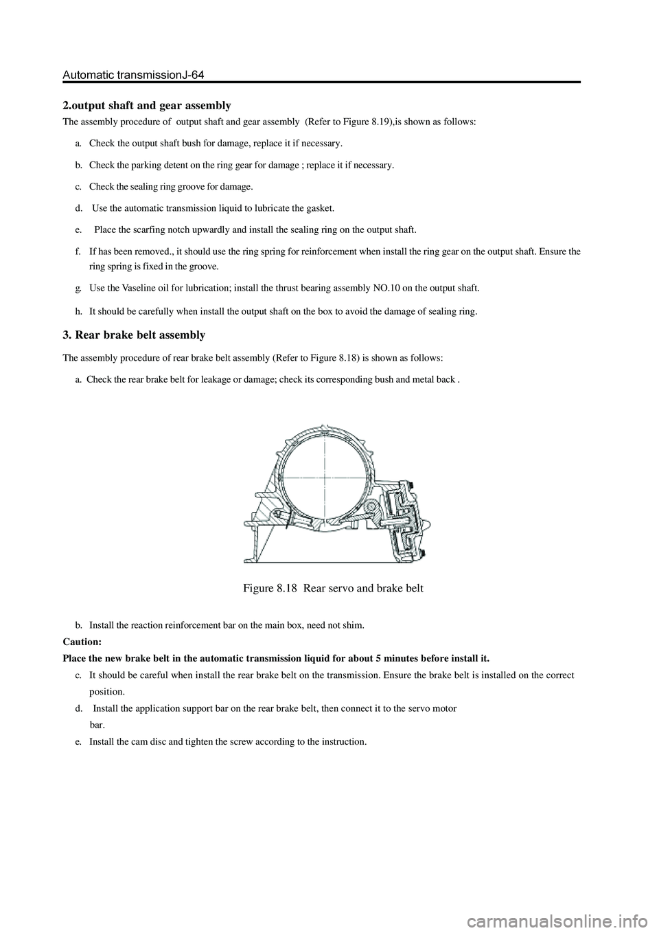
The assembly procedure of rear brake belt assembly (Refer to Figure 8.18) is shown as follows:
a. Check the rear brake belt for leakage or damage; check its corresponding bush and metal back .
Figure 8.18 Rear servo and brake belt
b. Install the reaction reinforcement bar on the main box, need not shim.
Caution:
Place the new brake belt in the automatic transmission liquid for about 5 minutes before install it.
c. It should be careful when install the rear brake belt on the transmission. Ensure the brake belt is installed on the correct
position.
d. Install the application support bar on the rear brake belt, then connect it to the servo motor
bar.
e. Install the cam disc and tighten the screw according to the instruction.