light GREAT WALL HOVER 2006 Service Repair Manual
[x] Cancel search | Manufacturer: GREAT WALL, Model Year: 2006, Model line: HOVER, Model: GREAT WALL HOVER 2006Pages: 425, PDF Size: 26.05 MB
Page 14 of 425
Overview of the entire car-5
The friction, disc, single-diaphragm spring clutch, hydraulic control mechanism. The external diameter of friction disc D=225mm,
internal diameter d=150mm, material is F810.
Adjustment of clutch pedal:
1. Measure the height of clutch pedal (from pedal pad surface to floor) and free stroke of clutch pedal (fork bar pin clearance).
Standard height of clutch pedal: flush with the brake pedal, free stroke of clutch pedal is 5-15mm;
2. Readjust the free stroke of pedal after adjust the height of pedal; rotate the push bar to the standard value, then fix the bolt
and nut;
3. If the free stroke of clutch pedal is not within standard value, it should rotate the adjusting bolt to standard value, then fix
the bolt and nut. Do not move the push bar to main cylinder when adjust the free stroke of pedal;
4. If the free stroke of clutch pedal and clearance between the clutch pedal and floor when the clutch is disengaged de not
consist with the standard, this may by caused by the air in hydraulic system and failure of main cylinder or clutch. It can
discharge the air of system or dissemble and inspect the main cylinder or clutch.
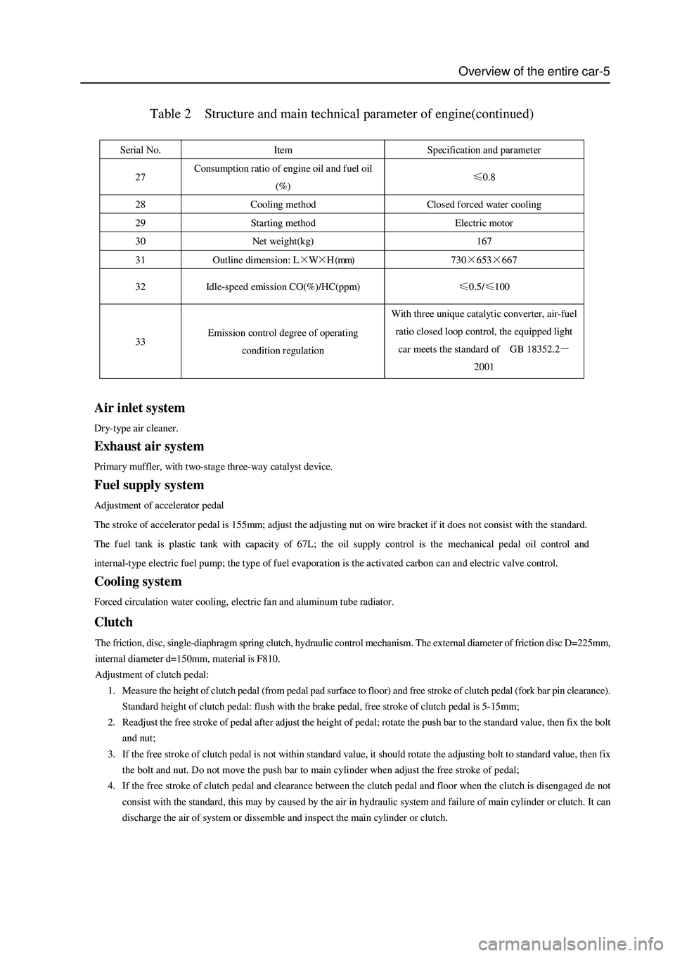
Table 2 Structure and main technical parameter of engine(continued)
Serial No. Item Specification and parameter
27 Consumption ratio of engine oil and fuel oil
(%) ≤0.8
28 Cooling method Closed forced water cooling
29 Starting method Electric motor
30 Net weight(kg) 167
31 Outline dimension: L×W×H (mm) 730×653×667
32 Idle-speed emission CO(%)/HC(ppm) ≤0.5/≤100
33 Emission control degree of operating
condition regulation With three unique catalytic converter, air-fuel
ratio closed loop control, the equipped light
car meets the standard of GB 18352.2-
2001
Air inlet system
Dry-type air cleaner.
Exhaust air system
Primary muffler, with two-stage three-way catalyst device.
Fuel supply system
Adjustment of accelerator pedal
The stroke of accelerator pedal is 155mm; adjust the adjusting nut on wire bracket if it does not consist with the standard.
The fuel tank is plastic tank with capacity of 67L; the oil supply control is the mechanical pedal oil control and
internal-type electric fuel pump; the type of fuel evaporation is the activated carbon can and electric valve control.
Cooling system
Forced circulation water cooling, electric fan and aluminum tube radiator.
Clutch
Page 16 of 425
Overview of the entire car-7
Suspension
The front suspension is the torsion bar spring, double-cylinder inflatable hydraulic damper, transverse stabilizer rod, double
cross-arm independent suspension. The distance between the center of front shaft of lower arm fixing nut and level ground is
295mm±1mm.
The rear suspension is the four-connecting rod, coil spring, double-cylinder inflatable hydraulic damper, transverse stabilizer
rod, no indep endent suspension.
Carriage
Peripheral trapezoidal structure; welded by two box section longitudinal beams and several box or tube section cross beams.
Steering system
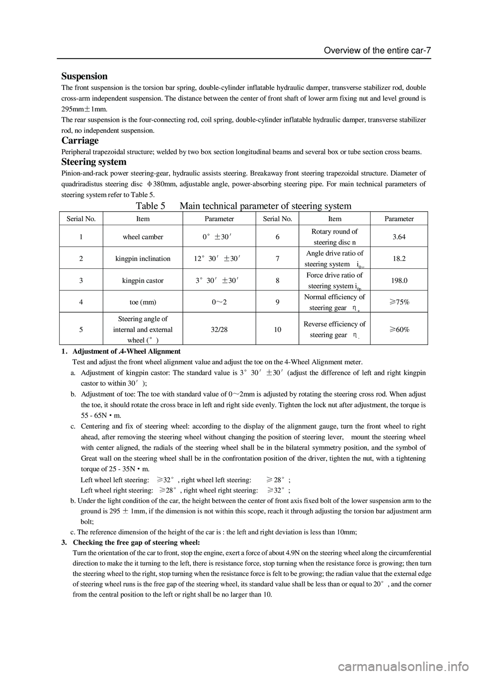
Pinion-and-rack power steering-gear, hydraulic assists steering. Breakaway front steering trapezoidal structure. Diameter of
quadriradistus steering disc φ380mm, adjustable angle, power-absorbing steering pipe. For main technical parameters of
steering s ystem refer to Table 5.
Table 5 Main technical parameter of steering system
Serial No. Item Parameter Serial No. Item Parameter
1 wheel camber 0°±30′ 6 Rotary round of
steering disc n 3.64
2 kingpin inclination 12°30′±30′ 7 Angle drive ratio of
steering system i0ω 18.2
3 kingpin castor 3°30′±30′ 8 Force drive ratio of
steering s ystem i0p 198.0
4 toe (mm) 0~2 9 Normal efficiency of
steering gear η+ ≥75%
5 Steering angle of
internal and external
wheel (°) 32/28 10 Revers e efficiency of
steering gear η- ≥60%
1.Adjustment of .4-Wheel Alignment
Test and adjust the front wheel alignment value and adjust the toe on the 4-Wheel Alignment meter.
a. Adjustment of kingpin castor: The standard value is 3°30′±30′(adjust the difference of left and right kingpin
castor to within 30′);
b. Adjustment of toe: The toe with standard value of 0~2mm is adjusted by rotating the steering cross rod. When adjust
the toe, it should rotate the cross brace in left and right side evenly. Tighten the lock nut after adjustment, the torque is
55 - 65N·m.
c. Centering and fix of steering wheel: according to the display of the alignment gauge, turn the front wheel to right
ahead, after removing the steering wheel without changing the position of steering lever, mount the steering wheel
with center aligned, the radials of the steering wheel shall be in the bilateral symmetry position, and the symbol of
Great wall on the steering wheel shall be in the confrontation position of the driver, tighten the nut, with a tightening
torque of 25 - 35N·m.
Left wheel left steering: 32, right wheel left steering:28;
Left wheel right steering:
28, right wheel right steering: 32;
b. Under the light condition of the car, the height between the center of front axis fixed bolt of the lower suspension arm to the
ground is 295
1mm, if the dimension is not within this scope, reach it through adjusting the torsion bar adjustment arm
bolt;
c. The reference dimension of the height of the car is : the left and right deviation is less than 10mm;
3. Checking the free gap of steering wheel:
Turn the orientation of the car to front, stop the engine, exert a force of about 4.9N on the steering wheel along the circumferential
direction to make the it turning to the left, there is resistance force, stop turning when the resistance force is growing; then turn
the steering wheel to the right, stop turning when the resistance force is felt to be growing; the radian value that the external edge
of steering wheel runs is the free gap of the steering wheel, its standard value shall be less than or equal to 20
, and the corner
from the central position to the left or right shall be no larger than 10.
Page 17 of 425
Brake system
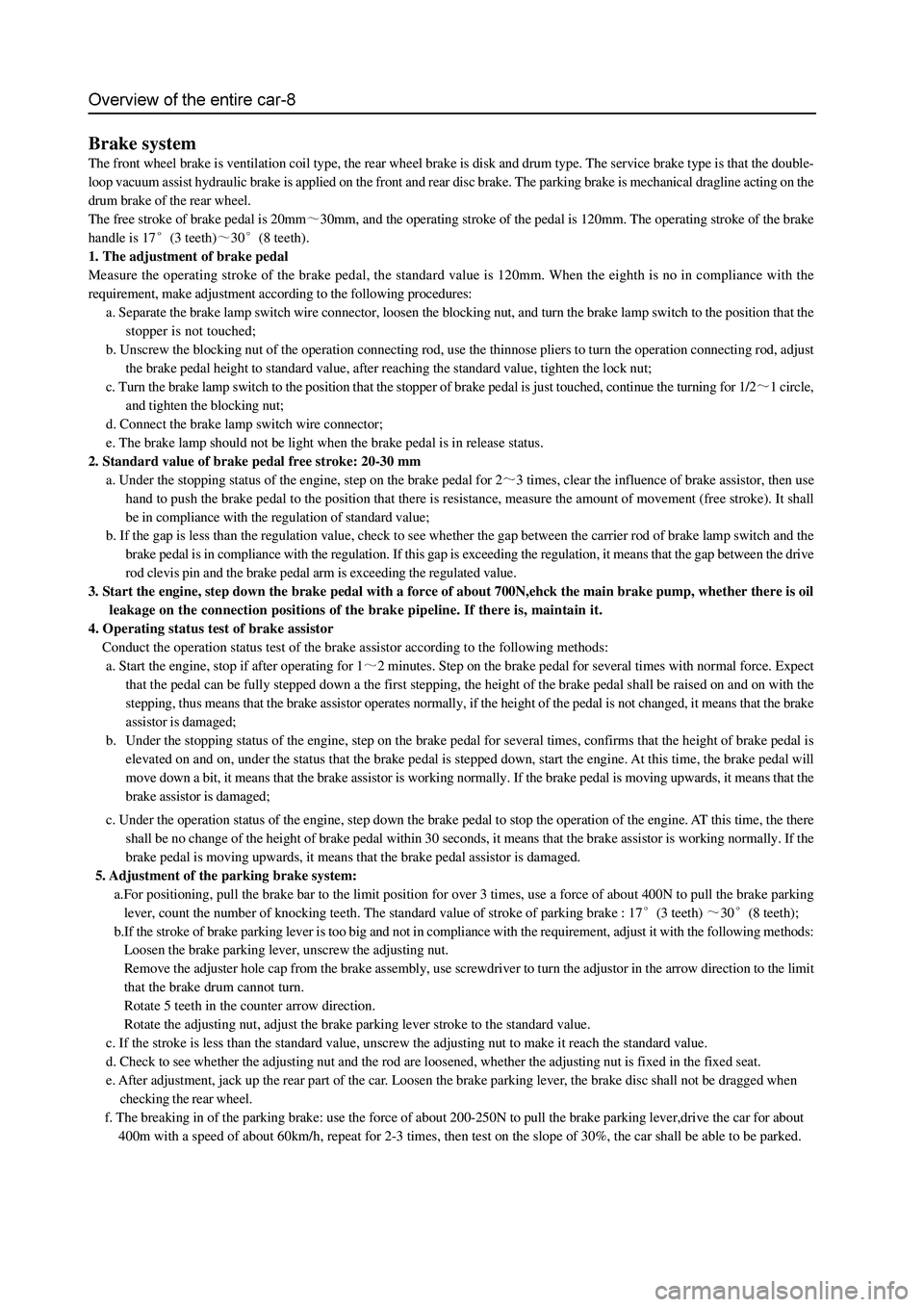
The front wheel brake is ventilation coil type, the rear wheel brake is disk and drum type. The service brake type is that the double-
loop vacuum assist hydraulic brake is applied on the front and rear disc brake. The parking brake is mechanical dragline acting on the
drum brake of the rear wheel.
The free stroke of brake pedal is 20mm
30mm, and the operating stroke of the pedal is 120mm. The operating stroke of the brake
handle is 17
(3 teeth)30(8 teeth).
1. The adjustment of brake pedal
Measure the operating stroke of the brake pedal, the standard value is 120mm. When the eighth is no in compliance with the
requirement, make adjustment according to the following procedures:
a. Separate the brake lamp switch wire connector, loosen the blocking nut, and turn the brake lamp switch to the position that the
stopper is not touched;
b. Unscrew the blocking nut of the operation connecting rod, use the thinnose pliers to turn the operation connecting rod, adjust
the brake pedal height to standard value, after reaching the standard value, tighten the lock nut;
c. Turn the brake lamp switch to the position that the stopper of brake pedal is just touched, continue the turning for 1/2
1 circle,
and tighten the blocking nut;
d. Connect the brake lamp switch wire connector;
e. The brake lamp should not be light when the brake pedal is in release status.
2. Standard value of brake pedal free stroke: 20-30 mm
a. Under the stopping status of the engine, step on the brake pedal for 2
3 times, clear the influence of brake assistor, then use
hand to push the brake pedal to the position that there is resistance, measure the amount of movement (free stroke). It shall
be in compliance with the regulation of standard value;
b. If the gap is less than the regulation value, check to see whether the gap between the carrier rod of brake lamp switch and the
brake pedal is in compliance with the regulation. If this gap is exceeding the regulation, it means that the gap between the drive
rod clevis pin and the brake pedal arm is exceeding the regulated value.
3. Start the engine, step down the brake pedal with a force of about 700N,ehck the main brake pump, whether there is oil
leakage on the connection positions of the brake pipeline. If there is, maintain it.
4. Operating status test of brake assistor
Conduct the operation status test of the brake assistor according to the following methods:
a. Start the engine, stop if after operating for 1
2 minutes. Step on the brake pedal for several times with normal force. Expect
that the pedal can be fully stepped down a the first stepping, the height of the brake pedal shall be raised on and on with the
stepping, thus means that the brake assistor operates normally, if the height of the pedal is not changed, it means that the brake
assistor is damaged;
b. Under the stopping status of the engine, step on the brake pedal for several times, confirms that the height of brake pedal is
elevated on and on, under the status that the brake pedal is stepped down, start the engine. At this time, the brake pedal will
move down a bit, it means that the brake assistor is working normally. If the brake pedal is moving upwards, it means that the
brake assistor is damaged;
c. Under the operation status of the engine, step down the brake pedal to stop the operation of the engine. AT this time, the there
shall be no change of the height of brake pedal within 30 seconds, it means that the brake assistor is working normally. If the
brake pedal is moving upwards, it means that the brake pedal assistor is damaged.
5. Adjustment of the parking brake system:
a.For positioning, pull the brake bar to the limit position for over 3 times, use a force of about 400N to pull the brake parking
lever, count the number of knocking teeth. The standard value of stroke of parking brake : 17
(3 teeth) 30(8 teeth);
b.If the stroke of brake parking lever is too big and not in compliance with the requirement, adjust it with the following methods:
Loosen the brake parking lever, unscrew the adjusting nut.
Remove the adjuster hole cap from the brake assembly, use screwdriver to turn the adjustor in the arrow direction to the limit
that the brake drum cannot turn.
Rotate 5 teeth in the counter arrow direction.
Rotate the adjusting nut, adjust the brake parking lever stroke to the standard value.
c. If the stroke is less than the standard value, unscrew the adjusting nut to make it reach the standard value.
d. Check to see whether the adjusting nut and the rod are loosened, whether the adjusting nut is fixed in the fixed seat.
e. After adjustment, jack up the rear part of the car. Loosen the brake parking lever, the brake disc shall not be dragged when
checking the rear wheel.
f. The breaking in of the parking brake: use the force of about 200-250N to pull the brake parking lever,drive the car for about
400m with a speed of about 60km/h, repeat for 2-3 times, then test on the slope of 30%, the car shall be able to be parked.
Page 18 of 425
Overview of the entire car-9
Car body
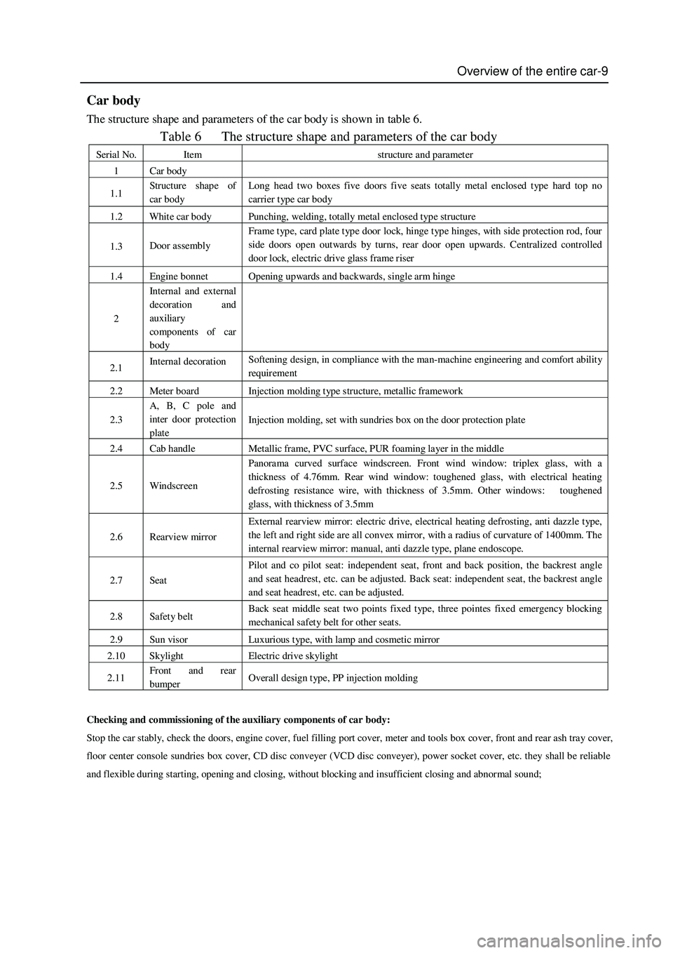
The structure shape and parameters of the car body is shown in table 6.
Table 6 The structure shape and parameters of the car body
Serial No. Item structure and parameter
1 Car body
1.1 Structure shap e of
car body Long head two boxes five doors five seats totally metal enclosed type hard top no
carrier t yp e car body
1.2 White car body Punching, welding, totally metal enclosed type structure
1.3 Door assembly Frame type, card plate type door lock, hinge type hinges, with side protection rod, four
side doors open outwards by turns, rear door open upwards. Centralized controlled
door lock, electric drive glass frame riser
1.4 Engine bonnet Opening upwards and backwards, single arm hinge
2 Int ernal and external
decoration and
auxiliary
components of car
body
2.1 Internal decoration Softening design, in compliance with the man-machine engineering and comfort ability
requirement
2.2 Meter board Injection molding type structure, metallic framework
2.3 A, B, C pole and
inter door protection
plate Injection molding, set with sundries box on the door protection plate
2.4 Cab handle Metallic frame, PVC surface, PUR foaming layer in the middle
2.5 Windscreen Panorama curved surface windscreen. Front wind window: triplex glass, with a
thickness of 4.76mm. Rear wind window: toughened glass, with electrical heating
defrosting resistance wire, with thickness of 3.5mm. Other windows: toughened
glass, with thickness of 3.5mm
2.6 Rearview mirror External rearview mirror: electric drive, electrical heating defrosting, anti dazzle type,
the left and right side are all convex mirror, with a radius of curvature of 1400mm. The
internal rearview mirror: manual, anti dazzle type, plane endoscope.
2.7 Seat Pilot and co pilot seat: independent seat, front and back position, the backrest angle
and seat headrest, etc. can be adjusted. Back seat: independent seat, the backrest angle
and seat headrest, etc. can be adjusted.
2.8 Safety belt Back seat middle seat two points fixed type, three pointes fixed emergency blocking
mechanical safety belt for other seats.
2.9 Sun visor Luxurious type, with lamp and cosmetic mirror
2.10 Skylight Electric drive skylight
2.11 Front and rear
bumper Overall design type, PP injection molding
Checking and commissioning of the auxiliary components of car body:
Stop the car stably, check the doors, engine cover, fuel filling port cover, meter and tools box cover, front and rear ash tray cover,
floor center console sundries box cover, CD disc conveyer (VCD disc conveyer), power socket cover, etc. they shall be reliable
and flexible during starting, opening and closing, without blocking and insufficient closing and abnormal sound;
Page 19 of 425
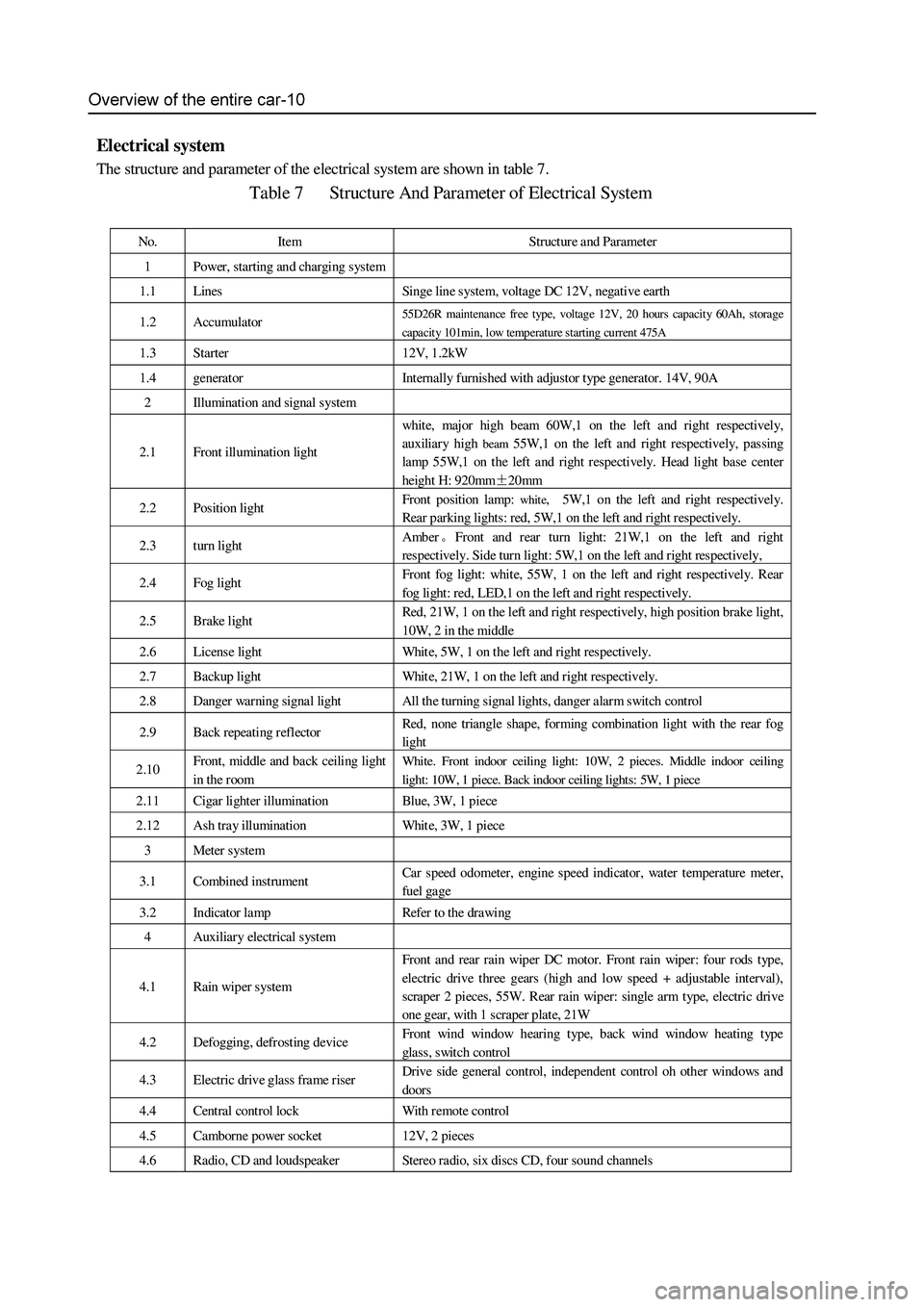
Electrical system
The structure and parameter of the electrical system are shown in table 7.
Table 7 Structure And Parameter of Electrical System
No. Item Structure and Parameter
1 Power, starting and charging system
1.1 Lines Singe line system, voltage DC 12V, negative earth
1.2 Accumulator 55D26R maintenance free type, voltage 12V, 20 hours capacity 60Ah, storage
capacity 101min, low temperature starting current 475A
1.3 Starter 12V, 1.2kW
1.4 generator Internally furnished with adjustor type generator. 14V, 90A
2 Illumination and signal s ystem
2.1 Front illumination light
white, major high beam 60W,1 on the left and right respectively,
auxiliary high
beam 55W,1 on the left and right respectively, passing
lamp 55W,1 on the left and right respectively. Head light base center
height H: 920mm±20mm
2.2 Position light Front position lamp: white, 5W,1 on the left and right respectively.
Rear parking lights: red, 5W,1 on the left and right respectively.
2.3 turn light Amber。Front and rear turn light: 21W,1 on the left and right
respectively. Side turn light: 5W,1 on the left and right respectively,
2.4 Fog light Front fog light: white, 55W, 1 on the left and right respectively. Rear
fog light: red, LED,1 on the left and right respectively.
2.5 Brake light Red, 21W, 1 on the left and right respectively, high position brake light,
10W, 2 in the middle
2.6 License light White, 5W, 1 on the left and right respectively.
2.7 Backup light White, 21W, 1 on the left and right respectively.
2.8 Danger warning signal light All the turning signal lights, danger alarm switch control
2.9 Back repeating reflector Red, none triangle shape, forming combination light with the rear fog
light
2.10 Front, middle and back ceiling light
in the room White. Front indoor ceiling light: 10W, 2 pieces. Middle indoor ceiling
light: 10W, 1 piece. Back indoor ceiling lights: 5W, 1 piece
2.11 Cigar lighter illumination Blue, 3W, 1 piece
2.12 Ash tray illumination White, 3W, 1 piece
3 Meter system
3.1 Combined instrument Car speed odometer, engine speed indicator , water t emperature met er,
fuel gage
3.2 Indicator lamp Refer to the drawing
4 Auxiliary electrical system
4.1 Rain wiper system Front and rear rain wiper DC motor. Front rain wiper: four rods type,
electric drive three gears (high and low speed + adjustable interval),
scraper 2 pieces, 55W. Rear rain wiper: single arm type, electric drive
one gear, with 1 scraper plate, 21W
4.2 Defogging, defrosting device Front wind window hearing type, back wind window heating type
glass, switch control
4.3 Electric drive glass frame riser Drive side general control, independent control oh other windows and
doors
4.4 Central control lock With r emote control
4.5 Camborne power socket 12V, 2 pieces
4.6 Radio, CD and loudspeaker Stereo radio, six discs CD, four sound channels
Page 20 of 425
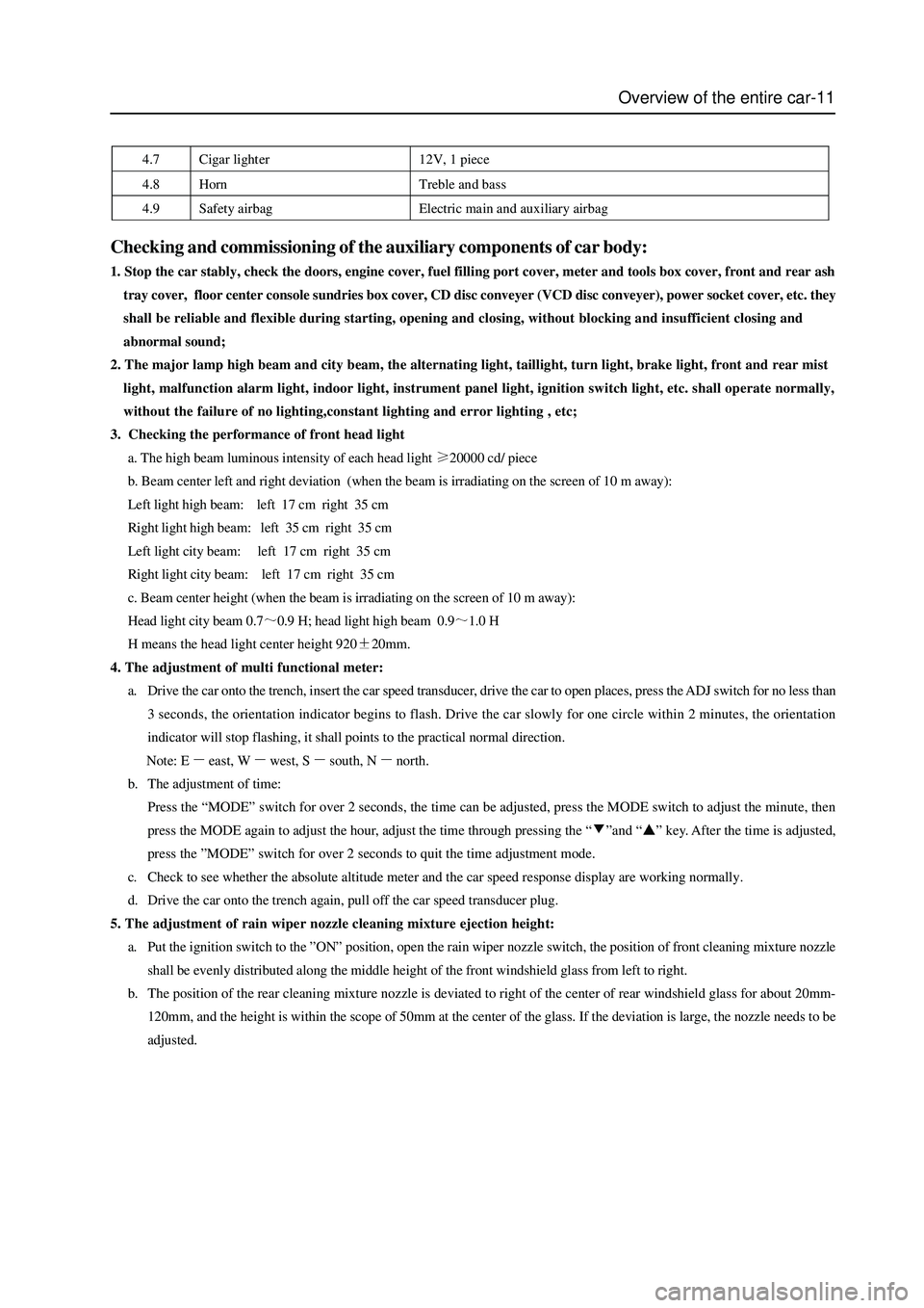
Overview of the entire car-11
4.7 Cigar lighter 12V, 1 piece
4.8 Horn Treble and bass
4.9 Safety airbag Electric main and auxiliary airbag
Checking and commissioning of the auxiliary components of car body:
1. Stop the car stably, check the doors, engine cover, fuel filling port cover, meter and tools box cover, front and rear ash
tray cover, floor center console sundries box cover, CD disc conveyer (VCD disc conveyer), power socket cover, etc. they
shall be reliable and flexible during starting, opening and closing, without blocking and insufficient closing and
abnormal sound;
2. The major lamp high beam and city beam, the alternating light, taillight, turn light, brake light, front and rear mist
light, malfunction alarm light, indoor light, instrument panel light, ignition switch light, etc. shall operate normally,
without the failure of no lighting,constant lighting and error lighting , etc;
3. Checking the performance of front head light
a. The high beam luminous intensity of each head light
20000 cd/ piece
b. Beam center left and right deviation (when the beam is irradiating on the screen of 10 m away):
Left light high beam: left 17 cm right 35 cm
Right light high beam: left 35 cm right 35 cm
Left light city beam: left 17 cm right 35 cm
Right light city beam: left 17 cm right 35 cm
c. Beam center height (when the beam is irradiating on the screen of 10 m away):
Head light city beam 0.7
0.9 H; head light high beam 0.91.0 H
H means the head light center height 920
20mm.
4. The adjustment of multi functional meter:
a. Drive the car onto the trench, insert the car speed transducer, drive the car to open places, press the ADJ switch for no less than
3 seconds, the orientation indicator begins to flash. Drive the car slowly for one circle within 2 minutes, the orientation
indicator will stop flashing, it shall points to the practical normal direction.
Note: E
east, Wwest, Ssouth, Nnorth.
b. The adjustment of time:
Press the “MODE” switch for over 2 seconds, the time can be adjusted, press the MODE switch to adjust the minute, then
press the MODE again to adjust the hour, adjust the time through pressing the “
”and “” key. After the time is adjusted,
press the ”MODE” switch for over 2 seconds to quit the time adjustment mode.
c. Check to see whether the absolute altitude meter and the car speed response display are working normally.
d. Drive the car onto the trench again, pull off the car speed transducer plug.
5. The adjustment of rain wiper nozzle cleaning mixture ejection height:
a. Put the ignition switch to the ”ON” position, open the rain wiper nozzle switch, the position of front cleaning mixture nozzle
shall be evenly distributed along the middle height of the front windshield glass from left to right.
b. The position of the rear cleaning mixture nozzle is deviated to right of the center of rear windshield glass for about 20mm-
120mm, and the height is within the scope of 50mm at the center of the glass. If the deviation is large, the nozzle needs to be
adjusted.
Page 33 of 425
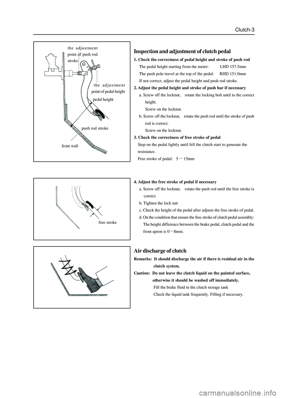
Clutch-3
Inspection and adjustment of clutch pedal
1. Check the correctness of pedal height and stroke of push rod
The pedal height starting from the meter: LHD 157.5mm
The push pole travel at the top of the pedal: RHD 151.0mm
If not correct, adjust the pedal height and push rod stroke.
2. Adjust the pedal height and stroke of push bar if necessary
a. Screw off the locknut, rotate the locking bolt until to the correct
height.
Screw on the locknut.
b. Screw off the locknut, rotate the push rod until the stroke of push
rod is correct.
Screw on the locknut.
3. Check the correctness of free stroke of pedal
Step on the pedal lightly until fell the clutch start to generate the
resistance.
Free stroke of pedal: 5
15mm
4. Adjust the free stroke of pedal if necessary
a. Screw off the locknut, rotate the push rod until the free stroke is
correct.
b. Tighten the lock nut
c. Check the height of the pedal after adjusts the free stroke of pedal.
d. On the condition that ensure the free stroke of clutch pedal assembly:
The height difference between the brake pedal, clutch pedal and the
front apron is 0
8mm.
Air discharge of clutch
Remarks: It should discharge the air if there is residual air in the
clutch system.
Caution: Do not leave the clutch liquid on the painted surface,
otherwise it should be washed off immediately.
Fill the brake fluid in the clutch storage tank
Check the liquid tank frequently. Filling if necessary.
the adjustment
point of push rod
stroke
the adjustment
point of pedal height
pedal height
front wall
free stroke
push rod stroke
Page 67 of 425
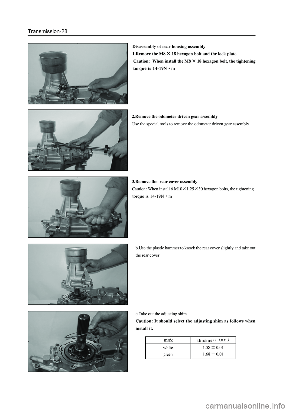
Disassembly of rear housing assembly
1.Remove the M8
18 hexagon bolt and the lock plate
Caution: When install the M8
18 hexagon bolt, the tightening
torque is 14-19N
m
2.Remove the odometer driven gear assembly
Use the special tools to remove the odometer driven gear assembly
3.Remove the rear cover assembly
Caution: When install 6 M10
1.2530 hexagon bolts, the tightening
torque is 14-19N
m
b.Use the plastic hammer to knock the rear cover slightly and take out
the rear cover
c.Take out the adjusting shim
Caution: It should select the adjusting shim as follows when
install it.
mark
Page 71 of 425
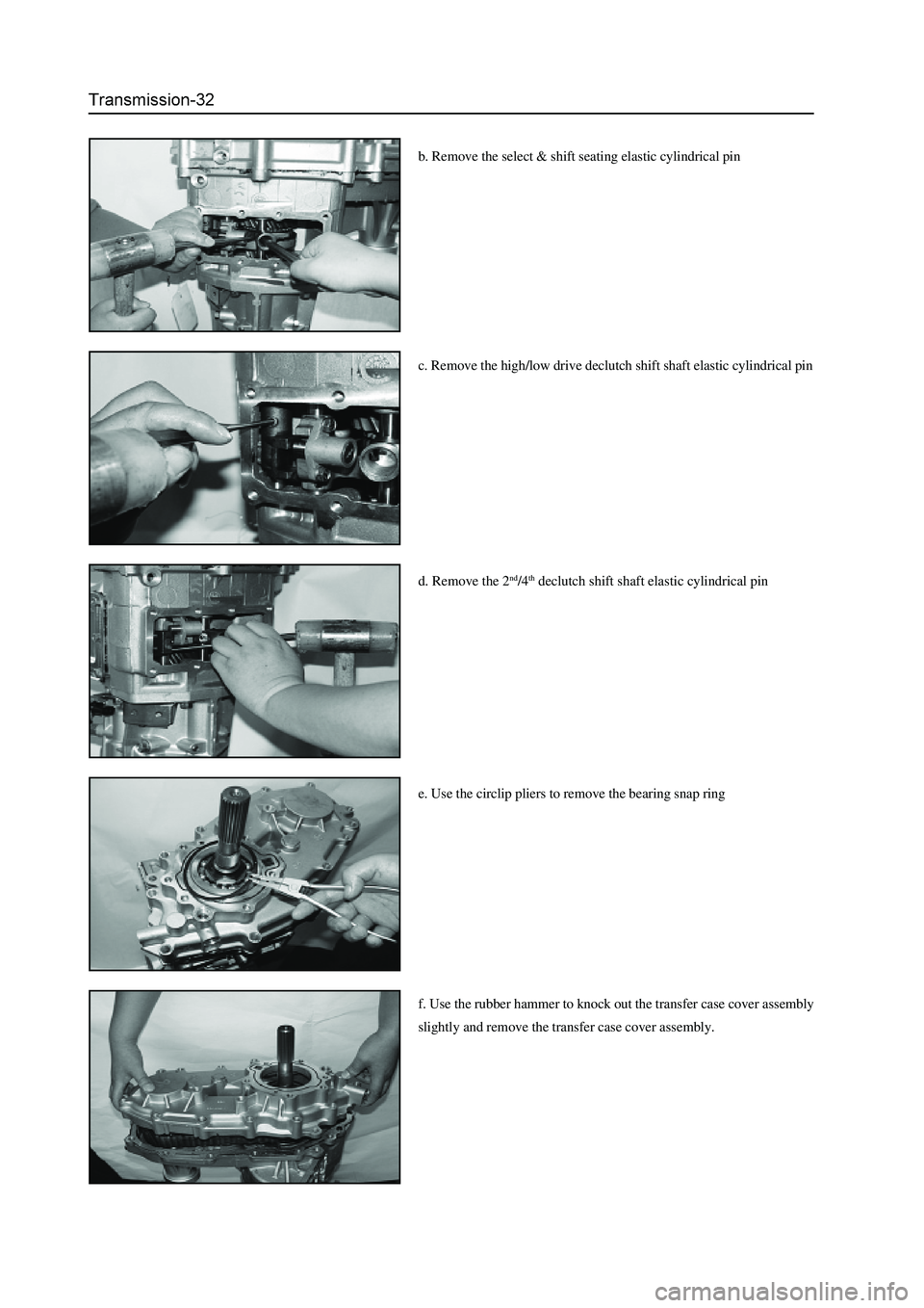
c. Remove the high/low drive declutch shift shaft elastic cylindrical pin
d. Remove the 2
nd/4th declutch shift shaft elastic cylindrical pin
e. Use the circlip pliers to remove the bearing snap ring
f. Use the rubber hammer to knock out the transfer case cover assembly
slightly and remove the transfer case cover assembly. b. Remove the select & shift seating elastic cylindrical pin
Page 72 of 425
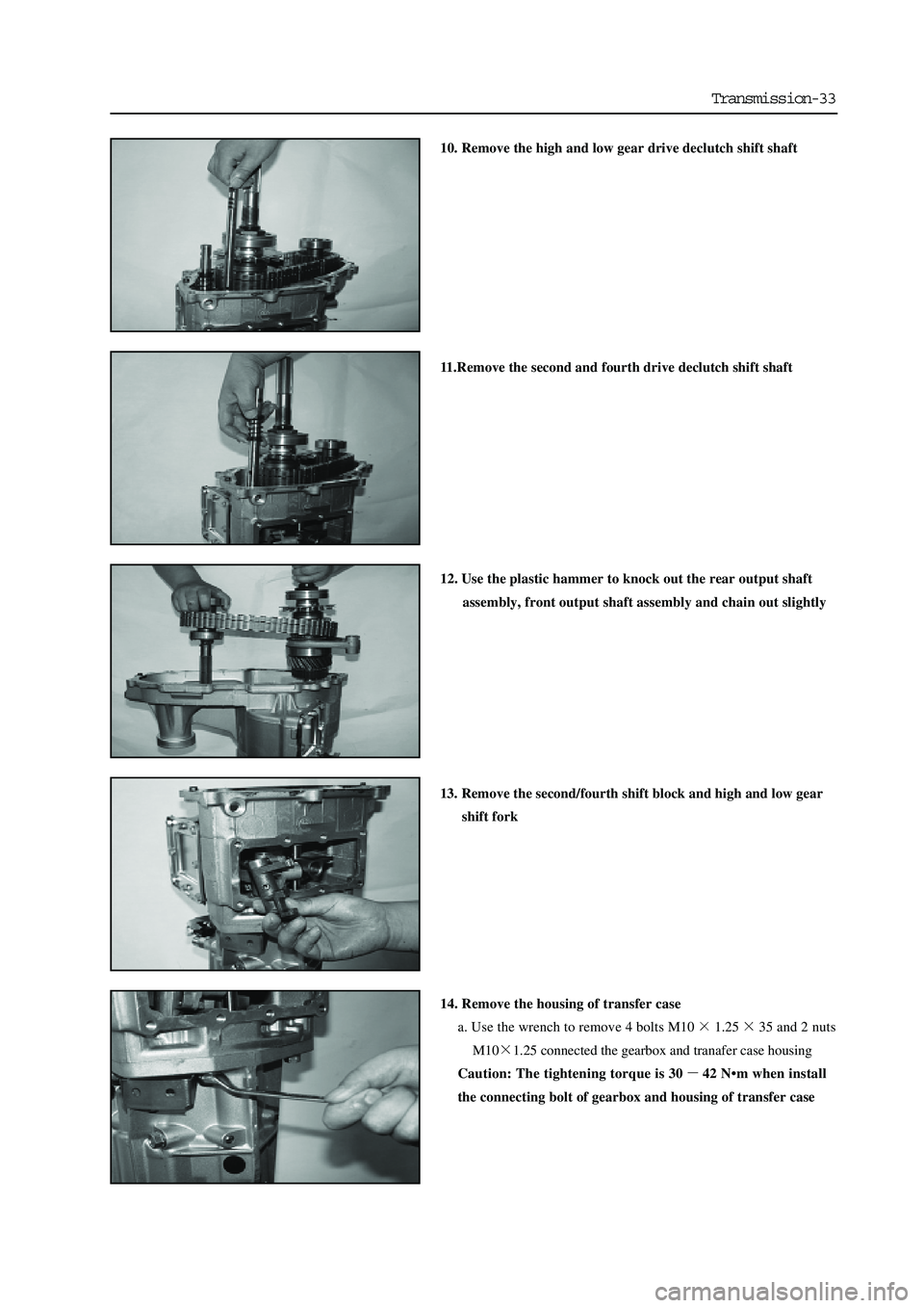
Transmission-33
10. Remove the high and low gear drive declutch shift shaft
11.Remove the second and fourth drive declutch shift shaft
12. Use the plastic hammer to knock out the rear output shaft
assembly, front output shaft assembly and chain out slightly
13. Remove the second/fourth shift block and high and low gear
shift fork
14. Remove the housing of transfer case
a. Use the wrench to remove 4 bolts M10
1.2535 and 2 nuts
M10
1.25 connected the gearbox and tranafer case housing
Caution: The tightening torque is 30
42 N•m when install
the connecting bolt of gearbox and housing of transfer case