Code 38 HONDA CIVIC 1997 6.G Workshop Manual
[x] Cancel search | Manufacturer: HONDA, Model Year: 1997, Model line: CIVIC, Model: HONDA CIVIC 1997 6.GPages: 2189, PDF Size: 69.39 MB
Page 767 of 2189
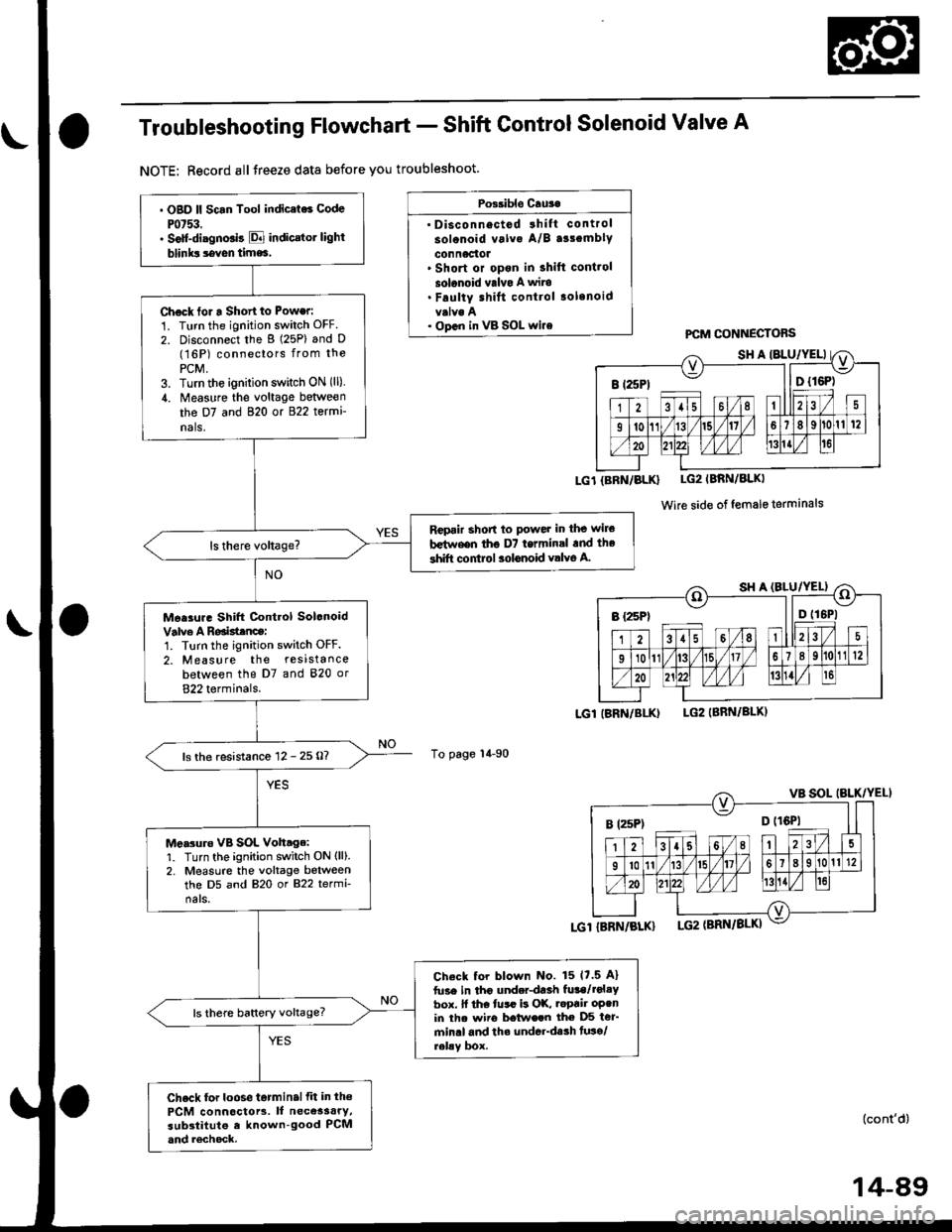
Troubleshooting Flowchart - Shift Control Solenoid Valve A
NOTE: Record allJreeze data before you troubleshoot.
Possible Cru3.
' Disconnectod 3hift control
solonoid valva A/B a33emblY
connactot. Short or opon in shift cont.ol
solonoid valvo A wits. Faulty shift control .olenoid
. op.n in vB SOL wi.e
To page 14-90
PCM CONNECTOBS
LG1{BRN/BLK} LG2IBRN/BLKI
Wire side of female terminals
LGl IBRN/BI-K)LG2IBBN/BLK)
. OBD ll Scan Tool indic.ts6 Code
Pot53.. Solt-diagno.is E indicrtot light
blinks seven time6.
Chock tor a Short to Power:
1. Turn the ignition switch OFF.
2. Disconnect the g (25P) and D(16P) conneclors from the
PCM,3. Turn the ignirion switch ON (ll)
,1. Measure the voltage between
the D7 and 820 or 822 termi
nals,
Rcpair short to powet in the wile
b€t^reen tho D7 termin.l .nd the
shift control aolonoid valve A.
Mee3ur. Shift Control Solonoid
Valve A Roaisttnce:1. Turn the ignition switch OFF.
2. Measure the resistance
between the D7 and 820 or
822 terminals.
ls the resistance 12 - 25 O?
Me.3uro vB SOL Voh.ge:1. Turn the ignition switch ON (ll).
2. Measure the voltage betweenthe D5 and 820 or 822 termi-
nals.
Check tor blown No. 15 17.5 A)
fuse in tho underdaah fula/rol.Ybox. ll the tusr is OK, .epair oPenin th. wiio betwe.n the D5 ter'min.l and th. underdssh tuso/relav box.
ls there baftery voltage?
Check for loose t6tminalfit in th€
PCM connoctors. It necessary,substitute e known-good PCMand rechock.
I t25Pt ll D {16P)
B rzsPt o trQil
(cont'd)
14-89
Page 769 of 2189
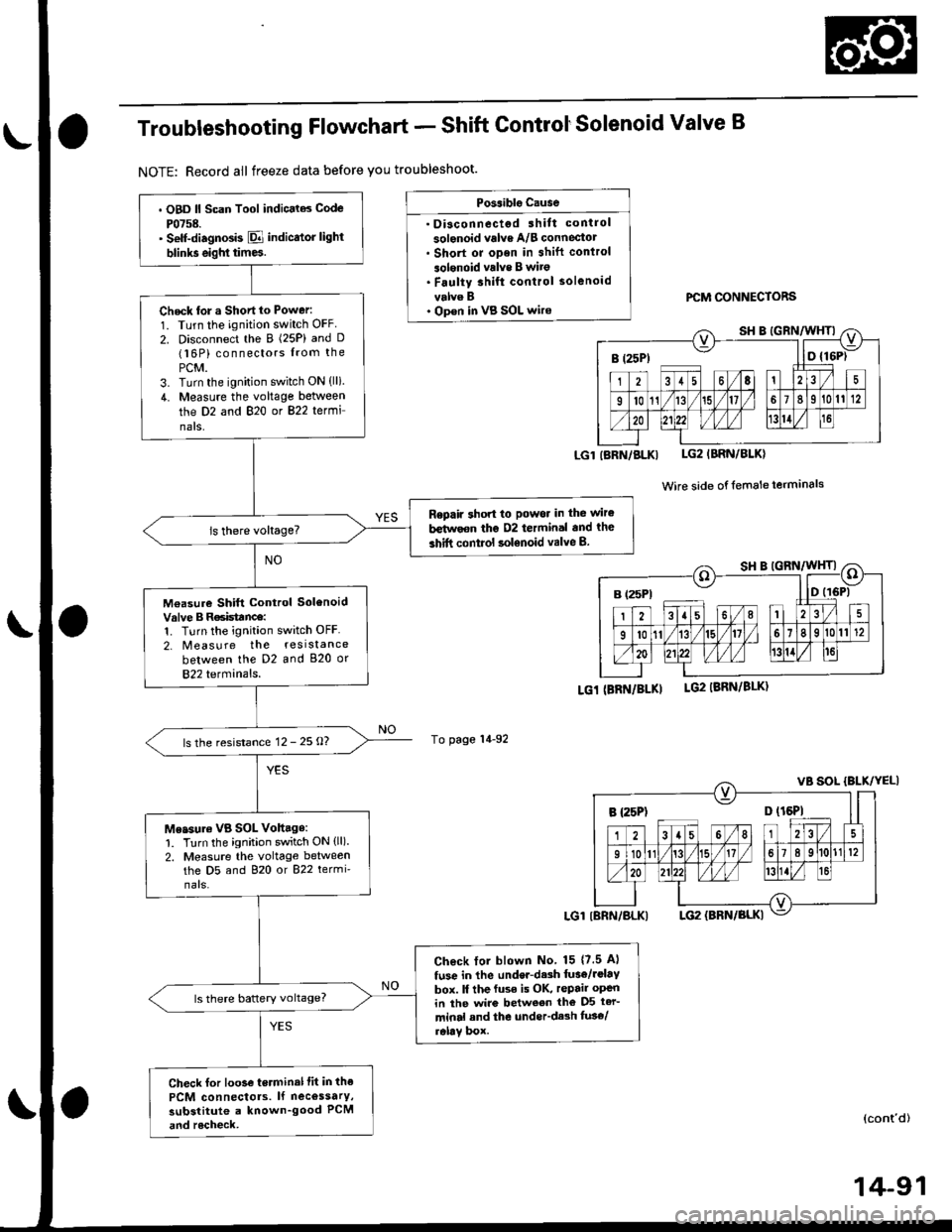
Troubleshooting Flowchart - Shift ControtSolenoid Valve B
NOTE: Record all freeze data before you troubleshoot.
Possiblg Cause
. Disconnectgd ihilt control
solenoid valve A/B conneciotr Short or oDen in shift conlrol
3olgnoid vrlve B wito. Faulty 3hift control solenoid
velve B. Op€n in VB SOL wirercM CONNECTORS
LGlIBRN/BLKI LG2IBRN/BLK)
Wire side of {emale terminals
LGi (BRi|/BLKILG2 IBRN/8LK)
To page 14-92
(cont'd)
14-91
. OBD ll Scan Tool indic.l6 Code
P0758.' Self-diagnosb El indicator light
blinks eighl tim6.
Check tor a Shortto Power:
1. Turn the ignition switch OFF
2. Disconnect the B (25P) and D(16P) connectors from the
PCM.3. Turn the ignition switch ON (lli.
4. Measure the voltage between
the D2 and 820 or 822 termi
nals,
Repaft 3hon to Powor in the wir€
b€tirvoon the D2 termin.l and the
3hift control solenoid valve B.
M€asure Shift Control SolenoidValve B R6isttnce:1. Turn the ignition switch OFF
2. Measure the resistance
between the D2 and 820 or
822 terminals.
ls the resistance 12 - 25 O?
Me.sure VB SOL Vohage:1. Turn the ignition switch ON (ll).
2. Measure the voltage betweenthe D5 and 820 or 822 termi'
nars.
Check lol blown No 15 {7.5 Al
fuse in the under-d.sh luae/rolav
box. ll the fuse is OK, repair open
in ihe wire between tho D5 ter-
minal and the under'dash fus€/relav box.
ls there battery voltage?
Check for loo3e terminal fit in the
PCM connectols. lf necossarY,
substitute a known_good PCM
and rocheck,
B (25Pt - I lD {16P)
B {25P1 D (t6Pl
Page 771 of 2189
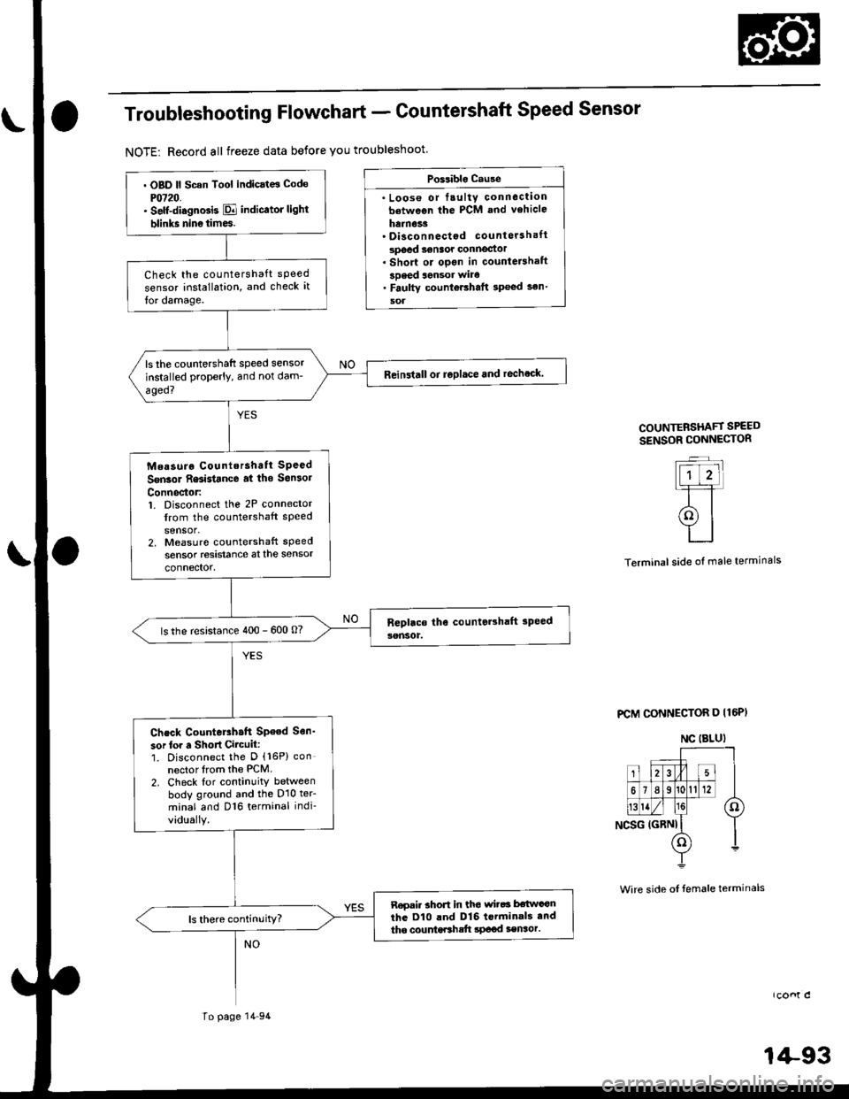
Troubleshooting Flowchart - Countershaft Speed Sensor
NOTE: Record all freeze data before you troubleshoot
Po$iblo Cause
. Loos€ or fsulty conneclionbetween the PCM and vehicle
hainoss' Disconnectod countersh.ft
spoed senaof connoctor. Short or opgn in counteBhaft
3Deed aensor wire. Faulty counloEhaft 3p€ed sen'
soa
COUNTERSHAFf SPEED
SENSOR CONNESTOR
Terminal side oI male terminals
FCM CONNECTOR D I16PI
rconl c
1+93
NC IBLUI
. OBD ll Scan Tool indicat6 Code
PO720.. Self-diagnosis E indicator light
blinks nin6times.
Check the countershaft sPeed
sensor installation, and check it
lor damage.
ls the countershaft speed sensor
installed properly, and not dam-
aged?
Reinstall or replace and rechock.
Measurg Counlershatt SPeed
Sgn3ol R6istance at tho Son3ol
Connector:1. Disconnect the 2P connector
from the countershaft sPeed
sensor.2, Measuro countershaft sPeed
sensor resistanca at the sensor
connector.
ls the resistance 400 - 600 O?
Chcck CounteEh.tt SPeed Sen'
sor lor a Short Circuit:1. Disconnect the D {16P) con
nector trom the PCM.2. Check lor continuity between
body ground and the D10 ter_
minal and D16 terminal indi-
vid!ally.
R6oai. short in tl|€ wi.6a bstwa€n
the D10 and D16 t.rminali end
tho countdthatt rP€od senaor.
To page 14 94
Wire side of temale terminals
Page 773 of 2189
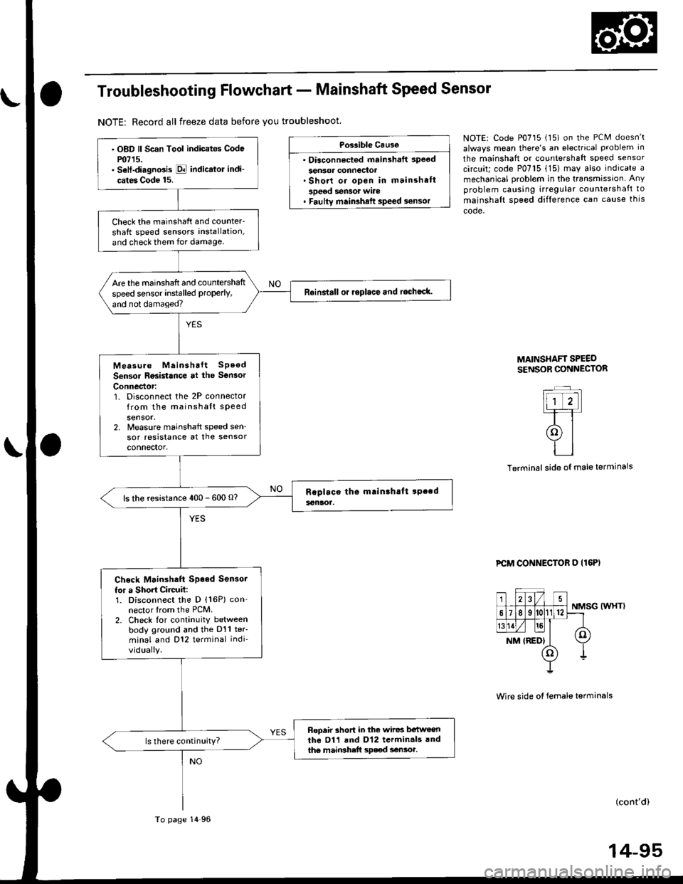
Troubleshooting Flowchart - Mainshaft Speed Sensor
NOTE: Record all freeze data before you troubleshoot.
Possible Causg
. Diaconn€cted mainshaft spoed
sen3or connector'Short or open in mainshaft
sDeed sen3or wile. Faulty main3halt speed sensor
NOTE: Code P0715 (15) on the PCM doesn't
always mean there's an electrrcal problem in
the mainshaft or countershaft speed sensor
circuit; code P0715 {15) may also indicate a
mechanical problem in the transmissjon Any
problem causing irregular countershaft to
mainshalt speed difference can cause thls
code.
lll ,..TT
(ol-i-l
tl
side oI male terminals
MAINSI{AFT SPEEDSENSOR CONNECTOR
Terminal
PCM CONNECTOR D (16P)
NMSG (WHT)
Wire side of female terminals
(cont'd)
14-95
. OBD ll Scan Tool indicates Codem715.. Sell-diagno3is E indicator indi-
cates Code 15.
Check the mainshaft and counter-
shatt speed sensors installation,
and check them for damage.
Are the mainshaft and countershaft
speed sensor installed properly,
and not damaged?
Rsinalall or replace and rocheck.
Mea3u.e Meinshalt SPeod
Sensor Residance al the Sen3or
Connector:1. Disconnect the 2P connectorfrom the mainshaft sPeedsensor.2, Nreasure mainshaft speed sen_sor resistance at the sensorconnector.
ls the resistance 400 - 600 O?
Check Mainshaft Sp.ed Sen3o.
for a Short Circult:1. Disconnect the D (16P) con-nector trom the PCM.2. Check lor continuity betweenbody ground and the D11 ter'minal and D12 terminal indi
vidually.
Bopair 3hort in the wiros b€twe€nthe 011 and D12 termin.ls rndth€ main3hett sp€€d aensoa.ls there continuity?
To page 14 96
Page 777 of 2189
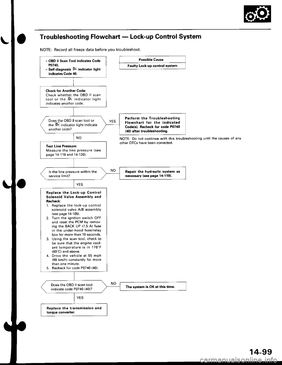
Troubleshooting Flowchart - Lock-up Control System
NOTE: Record all freeze data before vou troubleshoot.
Possibl€ Cause
Faulty Lock-up control sy3tem
NOTE: Do not continue with this troubleshootingother DTCS have been corrected.until the causes of any
OBD ll Scan Tool indicates Codem14/J.S€lf-diagnosis .D4l indicalor lightindicates Code 40.
Check for Another Code:Check whether the OBD ll scantool or the :E indicator lightindicates another code,
Perform the TroubleshootingFlowchart tor the indicatedCodels|. Rocheck to. code P0740(40) .fter troublBhooting.
ooes the OBD ll scan tool orrhe E indicator light indicateanother code?
Test Line Pressure:Measure the line pressure (see
page 14 119 and 14-120).
Repair the hydrrulic sy3tem asn6c6ssary (see page 14-1191.ls the lane pressure within theservice limit?
Replace the Lock-up ControlSolenoid Valve Assembly andRecheck:1. Replace the lock-up controlsolenoid valve A/B assembly(see page 14-105).2. Turn the ignition switch OFFand reset the PCM by removing the EACK UP (7.5 A) fusein the underhood {use/relaybox for more than 10 seconds.3. Using the scan tool, check tobe sure that the engine cool-ant temperature is in 176'F(80'C) and above.4. Drive the vehicle at 55 mph(88 km/h) constantly for morethan one minute,5. Recheck for code P0740 {40).
Does the OBD ll scan toolindicate code P0740 (40)?The svstem i3 OK .t this time.
14-99
Page 778 of 2189
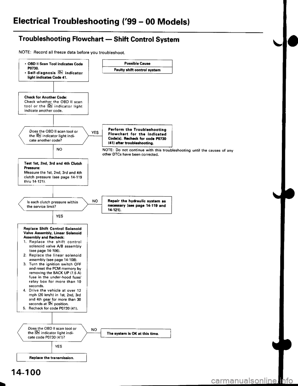
Electrical Troubleshooting ('99 - 00 Modelsl
Troubleshooting Flowchart - Shift Control System
NOTE: Record allfreeze data before you troubleshoot.
Po33ibl. Crus6
Frulty 3hift control ryrtom
. OBD ll Scan Tool indicrtd Codem730.. Self-dirgnosis E indicatorlight indicst€. Codo 41.
Check for Anoth€. Code:Check whether the OBD ll scantool or the E indicator lightindicate another code.
Prrf orm tho Troublc!hootingFlowch.rt for th. indicrt.dCod.l3l. R.ch.ck tor cod. m730141| .tt r troubldhootlng.
Doesthe OBD llscan tool orthe E indicator light indi-cate another code?
Test 13t, 2nd, 3rd .nd 4th ClutchPrglture:Measure the 1st, 2nd,3rd and 4thclutch pressure (see page 14-119thru 14 121).
R.prir tho hydrlulic ayrtam aan.c.3t..y lr.o p!9. lil-119 rnd1+1211.
ls each clutch pressure withinthe service limit?
Roplace Shift Control SolenoidValve Asembly. Linoar Sol.noidAssembly .nd Recheck:1. Replace the shift controlsolenoid valve A/B assembly(see page 14-106).2. Replace the linear solenoidassembly {see page 14-108}.3. Turn the ignition switch OFFand reset the PCM memory byremoving the BACK UP (7.5 A)fuse in the under-hood fuse/relay box for more than 10seconds,4. Drive the vehicle at over 12mph (20 kn/h) in 1st, 2nd, 3rdand 4th gear lo. more than 30seconds at lPll position.5. Recheck for code P0730 (41).
Doesthe OBD Ilscan tool orthe E ;ndicator light indi-cate code P0730 (41)?Th. sFtcm b OK .t this time.
NOTE: Do not continue with this lroubleshooting until the causes ot anyother OTCS have beon corrected.
I
14-100
Page 906 of 2189
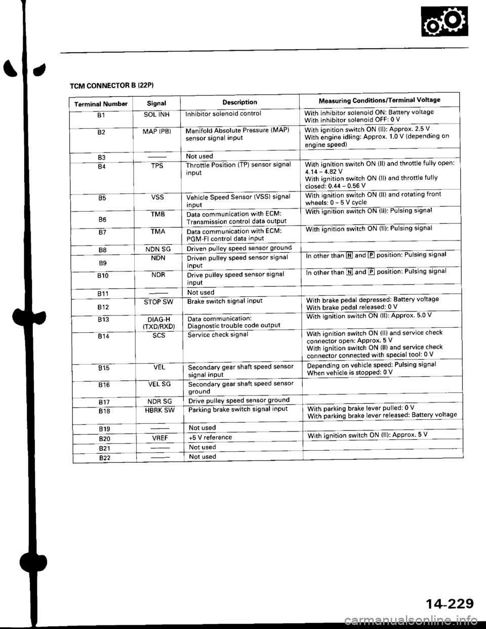
TCM CONNECTOR B (22P}
Terminal NumbelSignalDescriptionMeasuring Conditions/Terminal Voltage
B1SOL INHInhibitor solenoid controlWith inhibitor solenoid ON: Baftery voltage
With inhibitor solenoid OFF: 0 V
82MAP (PB)-M an if old Absol r-rte Pressure IMAP)
sensor signal inPUtWith iqnition switch ON (ll): Approx.2.5 V
With e;gine adling: Approx. 1.0 V (depending on
engine speed)
B3Not used
B4TPS-Throttle Position (TP) sensor signal
input
With ignition switch ON (ll) and throftle fully open:
4.14 - 4.42 VWith ignition switch ON (ll) and throttle fully
closed: 0.44 - 0.56 V
VSSVehicle Speed Sensor (VSS) signal
Inpur
With ignition switch ON (ll) and rotating front
wheelsr 0-5Vcycle
TMBData communication with ECM:
Transmission control data outpUt
With ignilion swltch UN lll): rulslng slgnar
81TMAData communication with EClvl:
PGM Fl control data inPut
With ignition swltch uN {ll,: l-ulslng slgnal
B8NDN SGDriven pulley speed sensor ground
B9NDNDriven pulley speed sensor signal
input
ln other thTnE and E position: Pulsing signal
810NDRDrive pulley speed sensor signal
Input
-tn ottrer ttran E ana E position: Pulsing signal
811Not used
812STOP SWBrake switch signal inPutWith brake pedal depressed: Battery voltage
With brake pedal released: 0 V
813DIAG-H(TXD/RXD)Data communication:Diagnostic trouble code outPut
Wittr ignitio.r s*itct' ON (ll): Approx 5.0 V
814Se-ice ctrect signatWith ignition switch ON (ll) and service check
connector oPen: APProx.5 V
With iqnition switch ON (ll) and service check
"onn"itot. connect"d with special tool: 0 V
Secondary gear shaft speed sensor
signal input
Depending on vehicle speed: Pulsing signal
When vehicle is stoPped: 0 V815VEL
816VEL SGSecondary gear shaft speed sensorgrouno
817NDR SGDrive pulley speed sensor ground
818HBRK SWParking brake switch signal inPutWith parking brake lever pulledr 0 V
With parking brake lever released: Battery voltage
819Not used
B�20VREF+5 V relerenceWith ignition switch ON (ll): Approx 5 V
821Not used
Not used
Page 911 of 2189
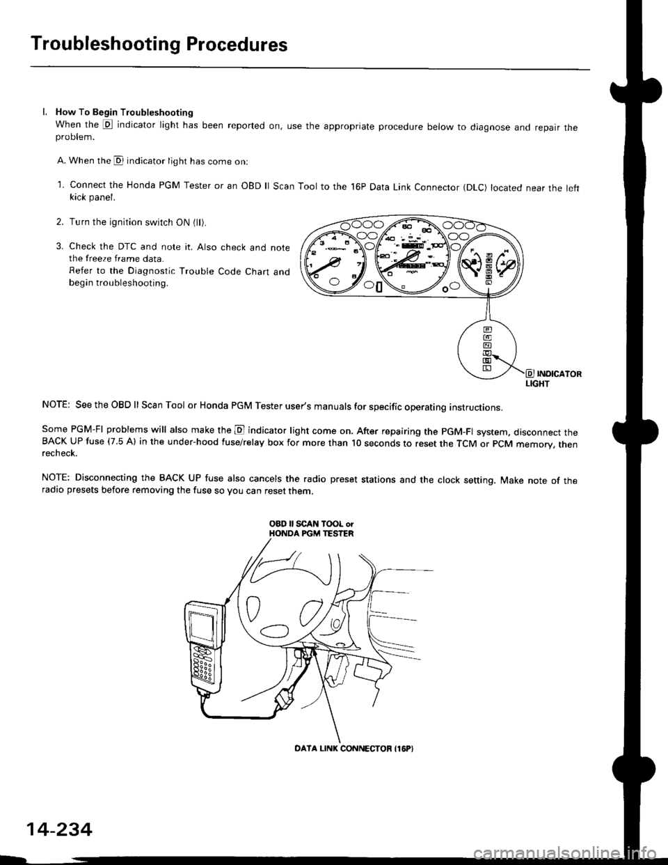
Troubleshooting Procedures
l. How To Begin Troubleshooting
When the E indicator light has been reported on, use the appropriate procedure below to diagnose and repatr theproDlem.
A. When the @ indicator light has come on:
l connect the Honda PGM Tester or an oBD ll Scan Tool to the 16P Data Link Connector (DLc) located near the leftkick panel.
Turn the ignition switch ON (ll).
Check the DTC and note it. Also check and notethe freeze frame data.
Refer to the Diagnostic Trouble Code Chart andbegin troubleshooting.
INOICATORLIGHT
NOTE: SeetheOBDll Scan Tool or Honda PGM Tester user's manuals for specific operating instructions.
Some PGM-FI problems will also make the E indicator light come on. After repairing the pGM-Fl system, disconnect theBACK UP fuse (7.5 Al in the under-hood fuse/relay box for more than l0 seconds to reset the TCM or PCM memory, rnenrecheck.
NOTE: Disconnecting the BACK UP fuse also cancels the radio preset stations and the clock setting. Make note of theradio presets before removing the fuse so you can reset them,
2.
3.
o0\e--loo
OATA LINK CONNECTOB I16P}
14-234
Page 912 of 2189
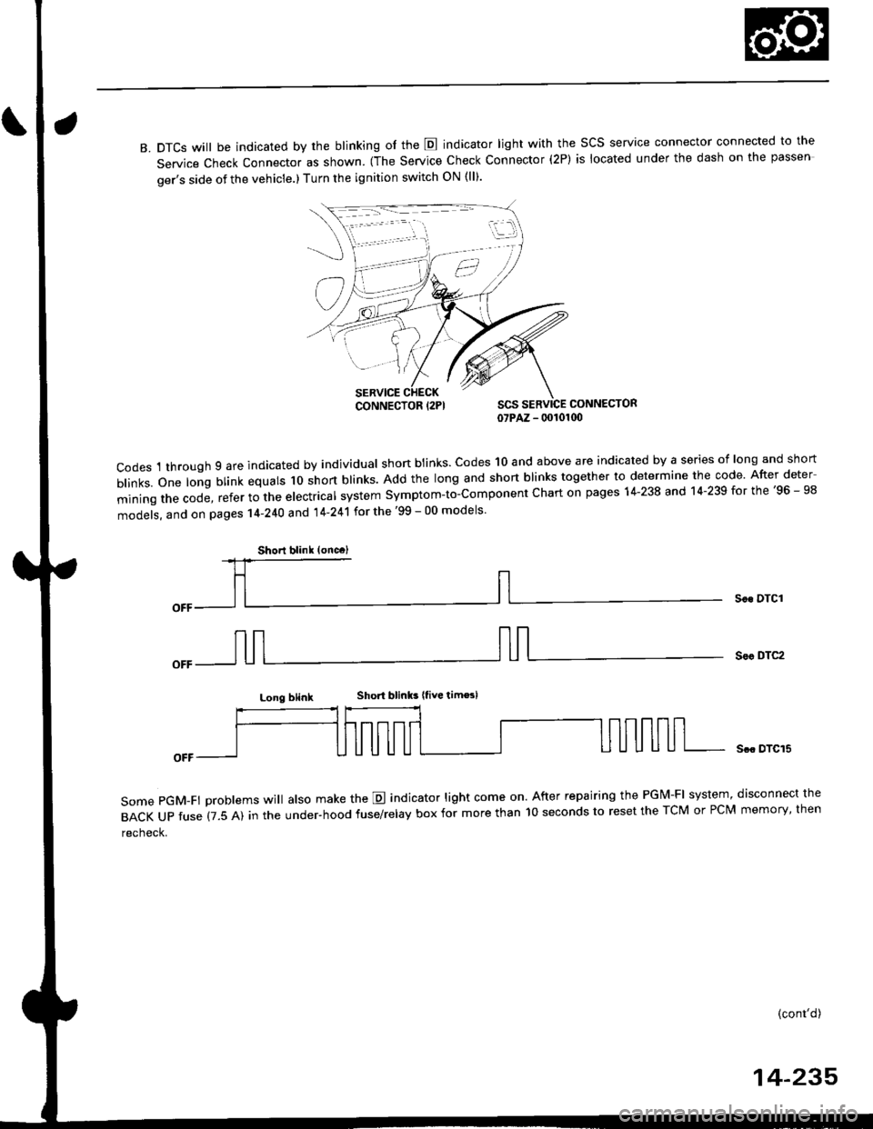
B. DTCS will be indicated by the blinking of the E indicator light with the SCS service connector connected to the
Service Check Connector as shown. (The Service Check Connector (2P) is located under the dash on the passen
ger's side of the vehicle.) Turn the ignition switch ON (ll).
CONNECTOR07PAZ - 00101(x)
codes 1 through 9 are indicated by individual shon btinks. codes 10 and above are indicated by a series of long and short
b|inks.one|ongblinkequa|sloshortb|inks.Addthe|ongandshortb|inkstogethertodeterminethecode.Afterdeter
miningthecode,refertothee|ectrica|systemsymptom-to-componentchartonpagesl4-238and14.239forthe,96_98
models, and on pages 14-240 and 14'241 for the '99 - 00 models
Soc DTCI
Sor DTC2
Long blinkShort blinks |tive tim€sl
some pGM-Ft problems wi
atso make the E indicator light come on. After repairing the PGM-FI system, disconnect the
BACKUPfuse(7.5A)intheUnder.hoodfuse/re|ayboxformorethanl0secondstoresettheTcMorPcMmemory,then
recheck.
Scc DTCI5
(cont'd)
14-235
iii:j
,,,/
CONNECTOR {2PI
Shorl blink (oncc)
Page 913 of 2189
Troubleshooting Procedures
(cont'd)
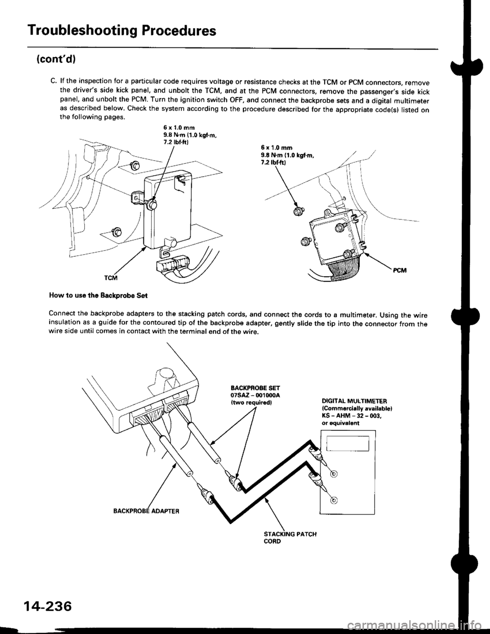
C. lf the inspection for a particular code requires voltage or resistance checks at the TCM or PCM connectors, removethe driver's side kick panel, and unbolt the TCM, and at the PCM connectors, remove the passenger's side kickpanel, and unbolt the PCM. Turn the ignition switch OFF, and connect the backprobe sets and a digital multimeteras described below. Check the system according to the procedure described for the appropriate code(s) listed onthe following pages.
6x1.0mm9.9 N.m {1.0 kgt m,
How to use lhe Backprob€ SE{
Connect the backprobe adapters to the stacking patch cords, and connect the cords to a multimeter, Using the wireinsulation as a guide for the contoured tip of the backprobe adapter, gently slide the tip into the connector from thewire side until comes in contact with the terminal end of the wire.
BACI(PROBE SET07saz - 001 txtoaItwo requirodlDIGITAL MULTIMETER(Commarcially avsibblelKS-AHM-32-(x)3,or oquivalent
6 x 'l,0 mm9.E N.m (1.0 kgf.m,7.2 rbtftt
coRo
14-236
ADAPTER