Code 38 HONDA CIVIC 1997 6.G Workshop Manual
[x] Cancel search | Manufacturer: HONDA, Model Year: 1997, Model line: CIVIC, Model: HONDA CIVIC 1997 6.GPages: 2189, PDF Size: 69.39 MB
Page 945 of 2189
Electrical Troubleshooting {'99 - 00 Models)
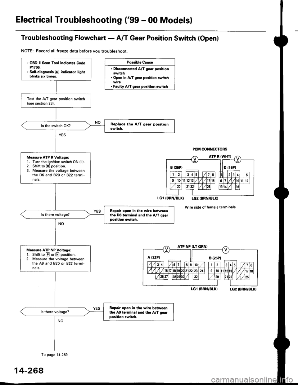
Troubfeshooting Flowchaft- AIT Gear Position Switch (Openl
NOTE: Record allfreeze data before vou troubleshoot.
Po$ible Cau3e
. Oilconnected A/T goar positionswitch. Op€n in A/T go.r po.ition switchwi?o. Faulty A/T gear polition switch
PCM @NNECTORS
(BRN/BI.XI LG2IBRN/BLKI
wire side of fomale terminals
I-G1 (BRN/BLKILG2 {BRN/BLK)
B {25P) I tO (16P1
ATP NP ILT GRNI
A t:r2Pt Il s tzspt
. OBD ll Scan Tool indicstE CodeP1706.. Selt-diagnGi! E indicato. lightblinks six tim€a.
Test the IVT gear position switch(see section 23).
Measu.e ATP R Voltage:1. Turn the ignition switch ON (ll).2. Shift to E position.
3. Measure the voltage betweenthe D6 and 820 or 822 termi-nals,
Ropair opcn in the wi.. hr.raGnth6 DO torminrl lnd the A/t g..rposition awitch.
Measure ATP NP Vohage:'1. Shift to E or N position.2. Measure the voltage betweenthe A9 and 820 ot 822 letmi-nals,
Ropair op6n in th€ wiro b€{woanthe Ag t.rminal and the A/T go..position .witch.
To page 14 269
14-264
Page 948 of 2189
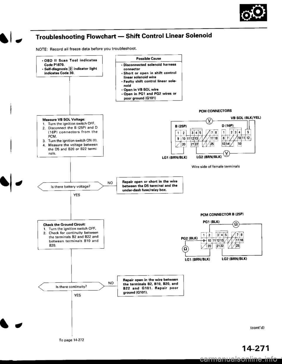
JTroubleshooting Flowchart - Shift Control Linear Solenoid
NOTE: Record all freeze data before you troubleshoot
Possiblc Cause
. Disconn€cted solenoid harnos3
connectol. Short or oDen in shilt controllinetr solonoid wiro. Faulty shift control linear sole_
noid. Op€n in VB SOL wite. ODen in PG'l and PG2 wires or
poor ground {G10'l)
f,
wire side ot female terminals
LG1 IBRN/BLKILG2IBRN/BLK)
{cont'd)
14-271
PCM CONNECTORS
B(25P) - Dll6P)
.OBD ll Scan Tool indicatos
Code P1870.. Solf-diagnosis E indic.lor light
indic.t€s Code 30.
M6a3ure VB SOL voltage:1. Turn the ignition switch OFF.
2. Disconnect the B 125P) and D(16P) connectors from the
PCM,3. Turn the ignition switch ON (ll).
4. Measure the voltage between
the D5 and 820 or 822 terminals.
Repair open or shod in the wire
between the D5 terminal and the
under-dash tuso/telay box.
Check the Ground Circuitl1. Turn the ignition switch OFF.2. Check lor continuity between
the terminafs 82 and 822 and
between terminals 810 and
820.
Repair open in the wi.e betwoen
the termin.ls 82, B10, B20, and
822 and G101. Repair Poolground (G101).
LG1 IBRN/BLKI
PCM CONNECTOR B PsPI
PG,I IBLK)
10 page 14-272
a
Page 950 of 2189
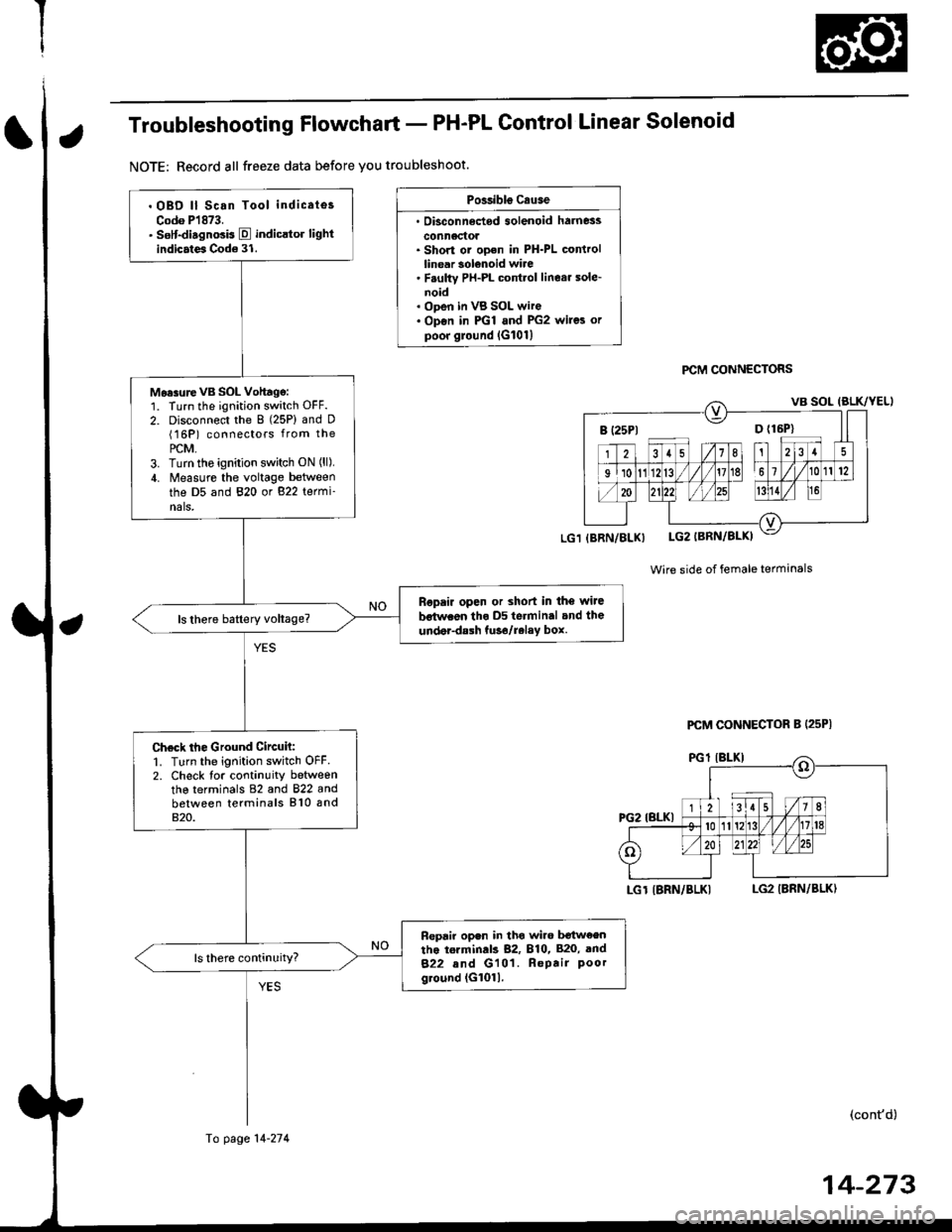
Troubleshooting Flowchart - PH-PL Control Linear Solenoid
NOTE: Record all freeze data before you troubleshoot.
Possibls c.use
. Oisconn6dod solenoid harness
conn6ctol. Short or ooen in PH-PL controllinear solenoid wire. F.ulty PH-PL cont.ol linear sole-noid. ODen in VB SOL wire. Op€n in PGl and PG2 wires orpoor ground lG101l
PCM CONNECTORS
Wire side of female terminals
LGT IBRN/BLKILG2 IBRN/BLK)
(cont'd)
B (25P1 D {16P}
. OBD ll Scan Tool indicates
Codo P1873.. sslt-disgnosis E indicltor lightindicates Code 31.
Mo.surevB SOL Vohagg:1. Turn the ignition switch OFF.
2. Disconnect the 8 (25P) and D(16P) connectors from the
PCM,3. Turn tho ignition switch ON (ll),
4. Measure the voltage between
the D5 and 820 or 822 termi-nals,
Ropair open or shod in the wiJe
bstwaon tho D5 terminal and the
under-dalh tuso/relay box.
Check the Ground Circuh:1. Turn the ignition switch OFF2. Check tor continuity betweenthe terminals 82 and 822 andbetween terminals 810 and820.
Fepair open in tho wiro b€tw€entho torminds 82, 810, 820, and
822 and G101. Repair Poorground (G1011.
(BRN/BLX)
Fo page 14-274
PCM CONNECTOR B (25P|
14-273
Page 952 of 2189
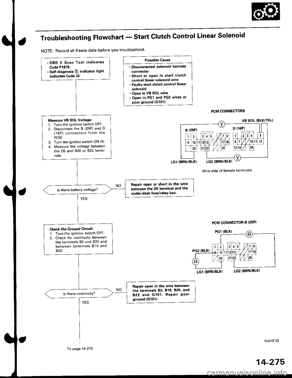
Troubleshooting Flowchart - Start
NOTE: Record all freeze data before you troubleshoot'
Clutch Control Linear Solenoid
PCM CONNECTORS
Wire side of lemale terminals
LGl (BRN/BLKI
(cont'd)
14-215
Po$ible Cause
. Disconnected solenoid harness
connedol. Short or open in sta.t clutch
control linear solenoid wiro. Faulty 3tart clutch conttol lin€ar
solenoid' Ooen in VB SOL wire. Open in PGI and PG2 wires or
poor ground {G101)
B l25P) -- o l16P)
'OBD ll Scan Tool indicates
Code Pl879.. self-diagnosis E indicstor light
indicates Code 32.
Measure VB SOL Voltag6:
1. Turn the ignition switch OFF
2. Disconnect the B {25P) and D(16P) connectors {rom the
PCM.3. Turn the ignition switch ON (ll).
4. Measure the voltage between
the D5 and 820 or 822 termi-
nals,
Reprir opon or short in the wire
between the D5 terminal and the
undei-d.sh luse/relaY box.ls there battery voltage?
Check the Ground Ciicuit:'1. Turn the ignition switch OFF.
2. Check for continuity between
the terminafs 82 and 922 and
between terminals 810 and
820.
Rep.ir open in the wire betwesn
the terminab 82, 810, 820. tnd
822 and G101. RePair Poorground lG101l.
ls there continuity?
LGl IBRN/BLK)
To page 14-276
PCM CONNECTOR B {25PI
Page 954 of 2189
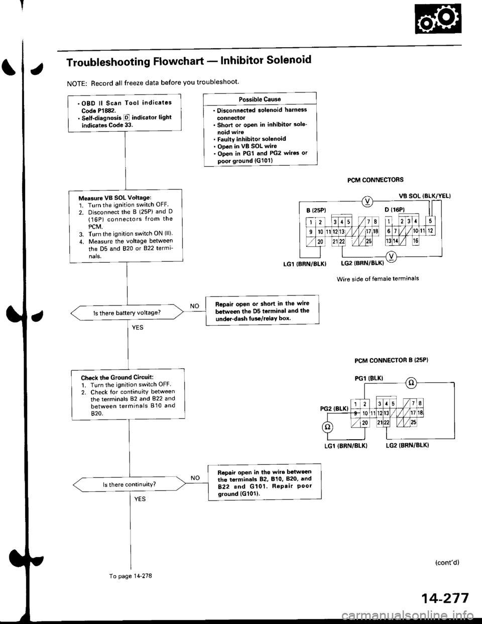
Troubleshooting Flowchart - lnhibitor Solenoid
NOTE: Record all freeze data before you troubleshoot'
Po3sible Cause
. Oi3connec'ted solenoid harn6s
connectoa. Shorl or open in inhibitor 3ole-
noid wir€. Faulty inhibitor solenoid. ODen in vB SOL wire. Open in PGl and PG2 wires or
poor ground {G101}
PCM CONNECTORS
Wire side ot female terminals
LGl IBRN/BLKILG2 (BRN/BLKI
(cont'd)
14-217
.OBD ll Scan Tool indicaies
Codo P'l882.. Self-diagnosis E indicttor light
indic.tes Code 33.
Me'sure VB SOL voltagel'1. Turn the ignition switch OFF.
2. Disconnect the B (25P) and D(16P) connectors from the
PCM.3. Turn the ignition switch ON (ll)
4. Measu.e the voltage between
the D5 and 820 or B22 termi-
nals.
Repair open or short in the wire
between the D5 tolminal and the
undor-dash lu36/relay box.ls there baftery voltage?
Ch€ck the Ground Circuit:
1. Turn the ignition switch OFF.
2. Check tor continuity between
the terminals 82 and 822 and
between terminals B'10 and
820.
R€pair open in the wire between
the torminal3 82, 810, B20, and
B22.nd G 101. RePair Poorground {G101).
(BRN/BLKI
To page 14-278
PCM CONNECTOR B {25P}
Page 956 of 2189
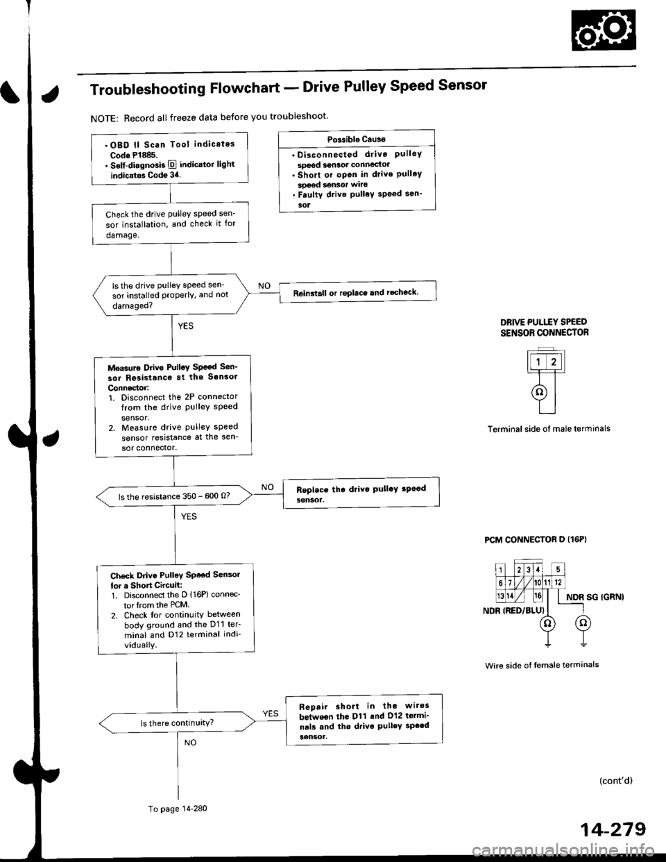
Troubleshooting Flowchart - Drive Pulley Speed Sensor
NOTE: Record allfreeze data before you troubleshoot'
Possible Cau3€
. Disconnected diive PulleYsoeed s6n3or connectol. Short or open in drive Pull.Ysooed sonsor wire. FaultY drive PulleY spo€d sen'
301
DRIVE PULEY SPEED
SENSOR @NNEfiOR
Terminal side of male terminals
PCM CONNECTOR D (16PI
NDR SG IGRNI
Wire side o{ Iemale terminals
(cont'd)
14-279
.OBD ll Scan Tool indicates
Code Pl885.. Selt-diagnosb E indicator light
indicatos Code 34
check the drive pulleY sPeed sen-
sor installation, and check it for
damage.
ls the drive PulleY speed sen-
sor installed properly, and not
damaged?
Rein3tall or roplace and techeck
Measuro Drive PulleY Speed Sen_
sor Ro3istanco at the Sonsol
Connector:1. Disconnect the 2P conneclor
from the drive Pulley speed
sensor,2. Measure drive Pulley speed
sensor resislance at the sen-
sor connecror.
ls the resistance 350 - 600 O?
Check Drivo PulleY SP6€d Sen3o.
lor . Short Circuit:1. Disconnect the D {16P) connec-
torlrom the PCM.
2. Check lor continuity between
body ground and the D11 ter
minal and D'l2 terminal indi
vidually.
Repai. short in the wiles
between the Dll lnd D12 termi-
nals and iho drive Pull.Y speed
To page 14-280
Page 958 of 2189
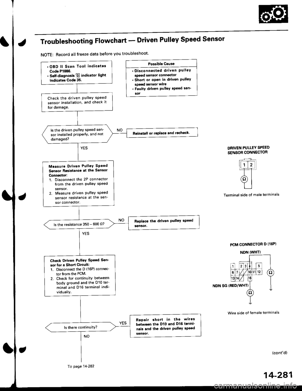
Troubleshooting Flowchart - Driven Pulley Speed Sensor
NOTE: Record all freeze data betore you troubleshoot'
Po3sible Caus€
' Oisconnected driven PulleYspeed s6nlor connoctor. Short or opon in d.iven Pulleysoeed sonsol wirc. Faulty driven Pulley speed sen_
sor
DRIVEN PULLEY SPEED
SENSOR CONNECTOR
Terminal side ol male terminals
FCM CONNECTOR D If6P)
NDN IWHTI
Wire side of female terminals
(cont'd)
'OBD lt Sc.n Tool indicates
Code Pl886.. Self-diagnosb E indicator light
indicrt€. Codo 35.
Check the driven Pulley speed
sensor installation, and check it
Ior damage.
lsthe driven pulleY speed sen'
sor installed ProPerly, and not
damaged?
Boin3tall or ropl.ca and recheck.
M..sure Drivon PulloY SPoed
Sonsor Rosblanco at the S6n3or
Conn6ctori1. Disconnect the 2P connector
trom the driven PUlley sPeed
sensor,2. lveasure driven Pulley speed
sensor resistance at the sen_
sor connector.
ls the resistance 350 - 600 0?
Check Dtivon Pulloy SP€ed Sen'
sor for a Short Circuit:
1. Disconnect the D (16P) connec-
torfrom the PCM.
2. Check tor continuity between
body ground and the D10 ter'
minal and Dl6 terminal indi-
vidually.
Raoair shott in tho wi.6s
betwoon th. Dlo end D16 tormi'
nak .nd the ddven Pulley spo€d
Fo page 14'282
14-2A1
Page 960 of 2189
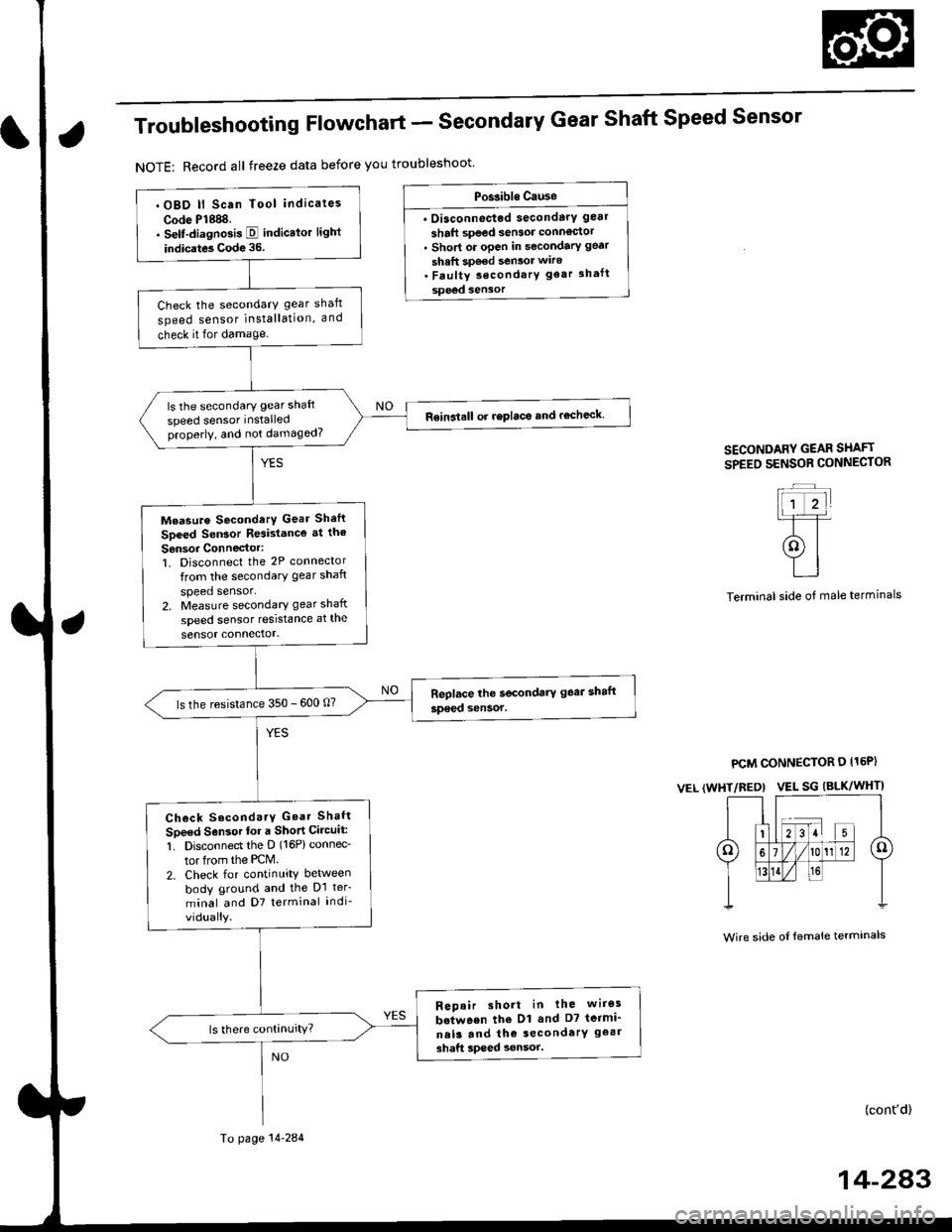
Troubleshooting Flowchart - Secondary Gear Shaft Speed Sensor
NOTE: Record all freeze data before you troubleshoot
Po$ible Causo
. Oisconnectod secondarY gear
shaft speed sensor conn66or' short or open in secondary gear
shaft spe€d sensor wiro. Faulty secondarY gear 3haft
sPeed sensor
SECONDARY GEAR SHAFT
SPEEO SENSOR CONNECTOR
Terminal side of male terminals
PCM CONNECTOR D I15P)
VEL (WHT/REO) VEL SG IALK/WHTI
Wire side oI female terminals
(cont'd)
14-243
' OBD ll Scan Tool indicates
Code P1888.. Self-diagnosis E indicalor light
indicats Code 35.
Check the secondarY gear shaft
speed sensor installation, and
check it for damage.
ls the secondary gear shaft
speed sensor installedproperly, and not damaged?
Reinatall or replace and rocheck.
Measure SocondarY Gear Sh.ft
Speed Sen3or Resistance at the
Sensor Connector:1. Disconnect the 2P connector
trom the secondary gear shaft
speed sensor.2. Measure secondary gear shaft
speed sensor resistance at the
sensor connector.
ls the resistance 350 - 600 0?
Check SecondarY Gear Shaft
Speed Sensor lor a Short Circuit:
1. Disconned the D (16P) connec-
tor from the PCM.
2. Check for continuity between
body ground and the D1 ter-
minal and D7 terminal indi-
vidually.
Repair short in the wiros
b.tween the Dl and D7 termi_
ne13 and th€ secondarY geal
3haft lpeed sonsor.
To page 14-284
Page 962 of 2189
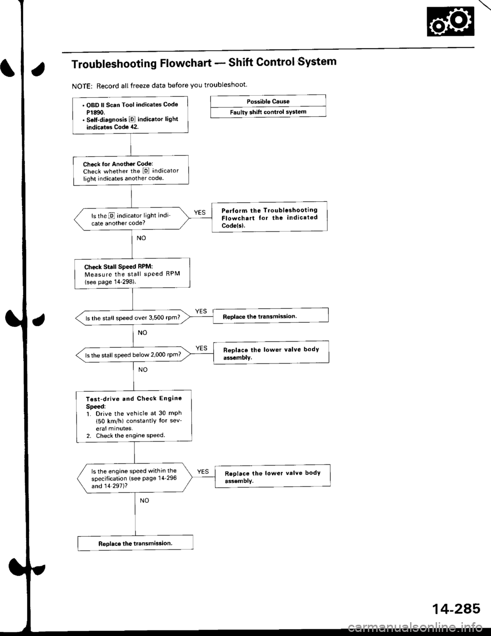
Troubleshooting Flowchart - Shift Control System
NOTE: Record allfreeze data before you troubleshoot
Possible cause
Faultv shift control svstem' OBD ll Scan Tool indicates Codo
P1Ato.. Self-diagnosis E indicator light
indicatos Code 42.
Check for Anoth€r Code:Check whether the E indicator
light indicates another code.
P€rform the Tloubleshooting
Flowchart for the indicated
Code(sl.
ls the E indicator light indi
cate another code?
Check Stall Speed RPM:
Measure the stall sPeed RPM(see page 14-298).
ls the stall speed over 3,500 rpm?
ls the stall speed below 2,000 rpm?
Test-drive and Check Engine
Speed:L Drive the vehicle at 30 mph
150 km/h) constantly for sev-
eral mlnutes.2. Check the engine speed
ls the engine speed within the
specification (see Page 14'296
and 14'297)?
14-245
Page 963 of 2189
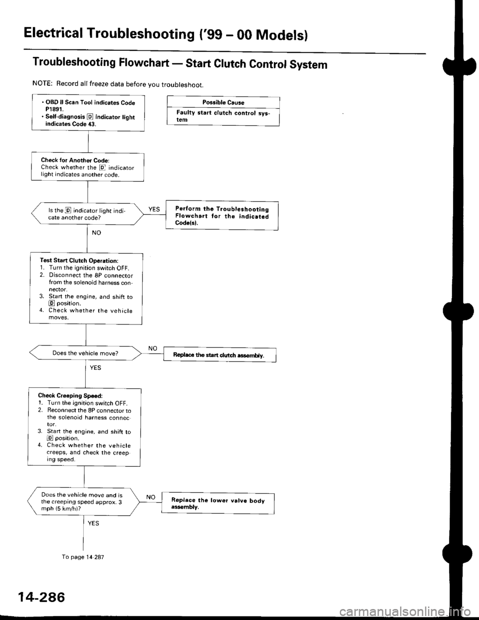
Electrical Troubleshootang ('gg - 00 Models)
Troubleshooting Flowchart - Start Clutch Control System
Possibl€ Cause
Faultv start clutch control sys-lem
NOTE: Record allfreeze data before you troubleshoot.
fo page 14 287
. OBD ll Scan Tool indicates CodeP1891.. Self-diagnosis E indicator tightindicates Code 43.
Check for Another CodelCheck whether the E indicatorlight indicates another code.
Perform the TroubleshootingFlowchart tor the indic.tedCodelsl.
ls the E indicator light indi-cate another code?
Test Stsn Clutch Operation:1. Turn the ignition switch OFF.2. Disconnect the 8P connectorfrom the solenoid harness connector.3. Start the engine, and shift toE position.4. Check whether the vehiclemoves.
Repl.c€ the stan clutdt rasemHy.
Check Croeping Sp€6d:1. Turn the ignition switch OFF.2. Reconnect the 8P connector tothe solenoid harness connec
3. St€rt the engine, and shift toE posation.4. Check whether the vehiclecreeps, and check the creeping speed.
Does the vehicle move and isthe creeprng speed approx, 3mph (5 km/h)?
14-2A6