under-dash HONDA CIVIC 1998 6.G User Guide
[x] Cancel search | Manufacturer: HONDA, Model Year: 1998, Model line: CIVIC, Model: HONDA CIVIC 1998 6.GPages: 2189, PDF Size: 69.39 MB
Page 1215 of 2189
Troubleshooting
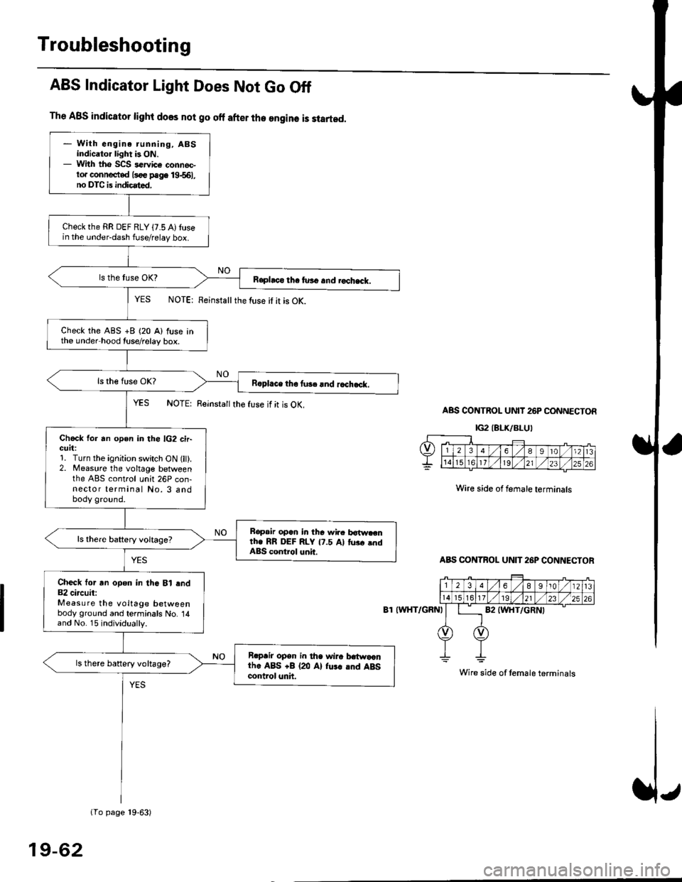
The ABS indicator light does not go off after the engine is started.
- With engine running, ABSindicator light is ON.- With tho SCS sewice connec-to. connected l3oe page 19-561,no DTC is indicated,
Checkthe RR DEF RLY {7.5 A)tusein the under-dash fuse/relay box.
Raphco tha furo and rochack.
Check the ABS +B (20 A) fuse inthe under hood tuse/relay box.
R6pl.ce tho tu3c lnd r.ch.ck.
Chock for an open in the lG2 cir-GUrt:1. Turn the ignition switch ON (lt).2. Measure the voltage betweenthe ABS control unh 26P con-nector terminal No. 3 andbody ground.
Bopair opcn in tha wir. botw.cnth. RR DEF RLY 17.5 Al tus. .ndABS control unit.
Check tor an opon in thG Bl end82 circuit:Measure the voltage betweenbody ground and terminals No. 14and No. 15 individually.
Rrpair opsn in tha wiro t atwa,anthe ABS +B (20 Al fu.r .nd ABScontrol unh.
ls there banery voltage?
1To page 19-63)
ABS Indicator Light Does Not Go Off
YES NOTE: Feinstattthe luse it it is OK.
YES NOTE: Reinsta
the fuse if it is OK.ABS CONTROL UNIT 26P CONNECTOR
IG2IELK/BLUI
Wire side of female terminals
ABS CONTBOL UN]T 26P CONNECTOR
8T IWHT/GRNI
Wire side of temale terminals
19-62
Page 1300 of 2189
Dashboard
Gomponent Removal/lnstallation
(cont'd)
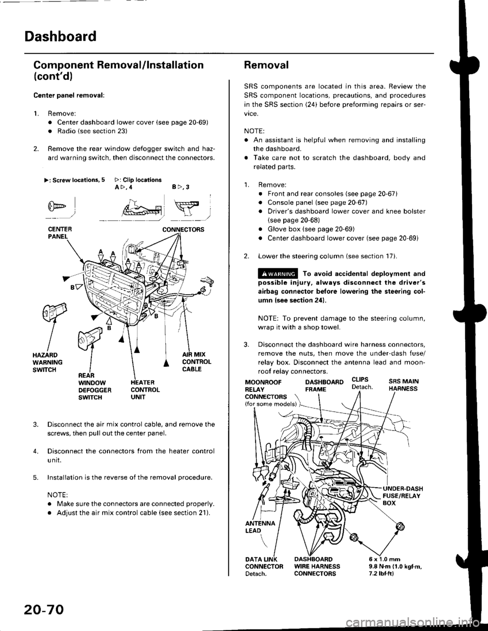
Center panel removal:
1. Remove:
. Center dashboard lower cover (see page 20-69)
. Radio {see section 23)
2. Remove the rear window defogger switch and haz-
ard warning switch, then disconnect the connectors.
>: Screw locations, 5 >: Clip locationsA>,4 B>,3
fii*-)
CENTERPANEI.
rt-xR.
W
IHAZARDWARNINGswlTcH
r44 "
F.IZvl
IIREARwtNoowOEFOGGERswtrcH
MtxCONTNOLCABLE
3. Disconnect the air mix control cable, and remove the
screws, then pull out the center panel.
4. Disconnect the connectors from the heater control
u nit.
5. Installation is the reverse of the removal procedure.
NOTE:
. Make sure the connectors are connected properly.
. Adjust the air mix control cable (see section 21).
20-70
Removal
SRS components are located in this area. Review the
SRS component locations, precautions, and procedures
in the SRS section (24) before preforming repairs or ser-
vice.
NOTE:
. An assistant is helpful when removing and installing
the dashboard.
. Take care not to scratch the dashboard, body and
related parts.
1. Remove:
o Front and rear consoles (see page 20-67)
. Console panel (see page 2O 67),
. Driver's dashboard lower cover and knee bolster(see page 20-68)
. Glove box (see page 20-69)
. Center dashboard lower cover (see page 20-69i
2. Lower the steering column (see section 17).
@ To avoid accidental deplovment and
possible injury, always disconnect the driver's
airbag connector belore lowering the steering col-
umn lsee section 241.
NOTE: To prevent damage to the steering column,
wrap it with a shop towel.
3. Disconnect the dashboard wire harness connectors,
remove the nuts, then move the under-dash fuse/
relay box. Disconnect the antenna lead and moon-
roof relay connectors.
DASHBOARD cltPs
CONNECTORS(for some models)
MOONROOFRELAY
ANTENNALEAO
FRAME
SRS MAINHARNESS
9.8 N.m (1.0 kgf m,7.2lbt.ltl
DATACONNECTOR WIRE HARNESSDetach. CONNECTORS
Page 1380 of 2189
Troubleshooting -'96 - 98 Models
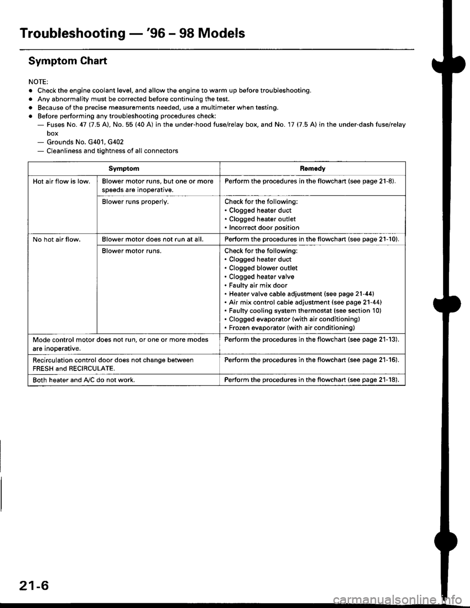
Symptom Chart
NOTE;
. Check the engine coolant level. and allow the engine to warm up before troubleshooting.
. Any abnormality must be corrected before continuing the test.
. Because of the precise measurements needed. use a multimeter when testing.
o Before performing any troubleshooting procedures check:- Fuses No. 41 11.5 Al, No. 55 (40 A) in the under-hood fuse/relay box. and No. 17 (7.5 A) in the under-dash fuse/relay
box- Grounds No. G401, G402- Cleanliness and tightness of all connectors
SymptomRomedy
Hot air flow is low.Blower motor runs. but one or more
speeds are inoperative.
Perform the procedures in the flowchart (see page 21-8).
Blower runs properly.Check for the following:. Clogged heater duct. Clogged heater outlet. Incorrect door position
No hot air flow.Blower motor does not run at all,Perform the procedures in the flowchart (see page 21-10).
Blower motor runs.Check for the following:. Clogged heater duct. Clogged blower outlet. Clogged heater valve. Faultv air mix door. Heater valve cable adjustment (see page 21-44). Air mix control cable adiustment (see page 2'l-441. Faulty cooling system thermostat (see section 10). Clogged evaporator (with air conditioning). Frozen evaporator {with air conditioning)
Mode control motor does not run, or one or more modes
are inooerative.
Perform the procedures in the flowchart (see page 21-13).
Recirculation control door does not chanqe between
FRESH and RECIRCULATE.
Perform the procedu.es in the flowchan (see page 21-16).
Both heater and A,/C do not work.Perform the procedures in the flowchart (see page 21-18),
21-6
Page 1387 of 2189
Mode Control Motor
To page 21-14
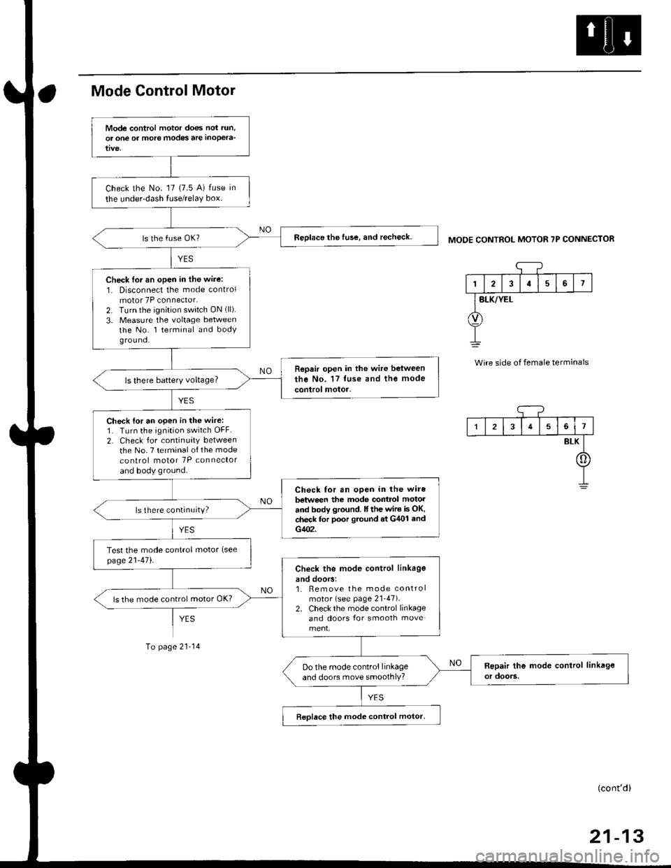
MODE CONTROL MOTOR 7P CONNECTOR
'1
I2I57
BLK/YEL
Wire side of female terminals
Mode control motor does not run,
or one of more modes are inoPela-
Check the No. '17 (7.5 A) fuse in
the under-dash fuse/relaY box.
Reolace the fuse, and recheck.
Check lor an open in the wire:
1. Disconnect the mode controlmotor 7P connector.2. Turn the ignition switch ON (ll).
3. Measure the voltage betweenthe No. l terminal and bodyg rou nd.
Repair open in the wire between
the No. 17 tuse and the mode
control motor.ls there batterY voltage?
Check {or an open in the wire:1. Turn the ignition switch OFF.
2. Check for continuity between
the No. 7 terminal of the mode
co nlrol motor 7P connector
and body ground.
Check for an open in the wire
batwe€n the mode contrcl motol
and body ground. lf the wir€ is OK,check for poor gtound at G/U)l and
G402.
ls there continuity?
Test the mode control motor (see
page21-471.Check the mod€ control linkage
and doors:1. Bemove the mode controlmotor (see page 21-47).2. Check the mode control linkageand doors for smooth move
ls the mode control motor OK?
Do the mode control linkageand doors move smoothlY?
Reolace the mode control motor,
I34561
BLK
[]
(cont'd)
Page 1390 of 2189
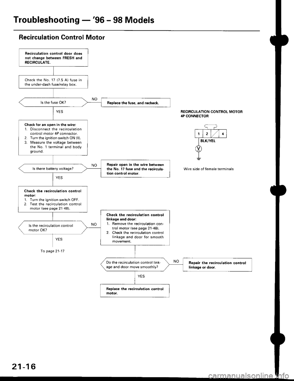
Troubleshooting -'96 - 98 Models
Recirculation Control Motor
Becirculation control door doesnot change between FRESH andRECIBCULATE.
check the No- 17 (7.5 A) fuse inthe under-dash fuse/relay box.
Reolace the tuse. and recheck.
Check for an open in the wire:1. 0isconnect the recirculationcontrol motor 4P connector.2. Tu.n the ignition switch ON (ll).
3. Measure the voltage betweenthe No. l terminal and bodyground.
Repair open in the wir6 betweenthe No. 17Iuse and the recircula-lion conlrol motor.ls there battery voltage?
Check lhe recirculation control
1. Turn the ignition switch OFF.2. Test the recirculation controlmotor {see page 21 48).
Check the recirculation controllinkage and door:1. Remove the recirculation con'trol motor {see page 21 48}.2. Check the recirculation controllinkage and door for smooth
Do the recirculation control linkage and door move smoothly?Reoair the r€circulation controllinkage or door.
RECIRCULATION CONTROL MOTOR4P CONNECTOR
BLK/YEI-
Wire side of temale terminals
Io page 21 17
21-16
Page 1393 of 2189
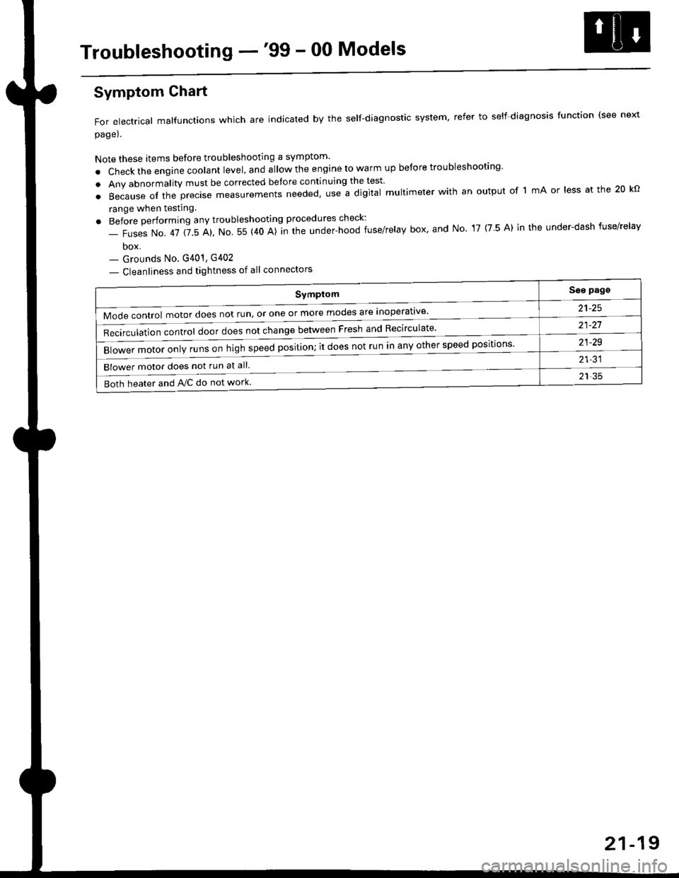
Troubleshooting -'99 - 00 Models
Symptom
Mode control motor does not run, or one or more modes are inoperat've'
Recirculation control door does not change between Fresh and Recirculate'
Blower motor only runs on high speed position; it does not run in any other speed positions
Blower motor does not run at all.
Both heater and Ay'C do not work
See pags
a1_tq
21-21
21-29
21-31
21 35
Symptom Chart
For electrical malfunctions which are indicated by the self-diagnostic system, refer to self-diagnosis function (see next
page).
Note these items before troubleshooting a symptom'
. Check the engine coolant level, and allow the engine to warm up before troubleshooting'
. Any abnormality must be corrected before continuing the test
.Becauseoftheprec|semeasurementsneeded,UseadigitaImu|timeterwithanoutputoflmAor|essatthe20ko
range when testing
. Before performing any troubleshooting procedures check:
- Fuses No. 41 115 Al, No 55 (40 A)]n the under-hood fuse/relay box' and No 17 (7 5 A) in the under-dash fuse/relav
box- Grounds No. G401, G402
- Cleanliness and tightness of all connectors
21-19
Page 1399 of 2189
![HONDA CIVIC 1998 6.G User Guide Mode control motor does not run.
or one or more modes arc inope]a-
tive.
Check the No. 17 (7.5 A) fuse in
the under-dash fuse/relay box.
Replace the Iuse. and recheck.
Check for an open in the wire:
1](/img/13/6068/w960_6068-1398.png "HONDA CIVIC 1998 6.G User Guide Mode control motor does not run.
or one or more modes arc inope]a-
tive.
Check the No. 17 (7.5 A) fuse in
the under-dash fuse/relay box.
Replace the Iuse. and recheck.
Check for an open in the wire:
1")
Mode control motor does not run.
or one or more modes arc inope]a-
tive.
Check the No. 17 (7.5 A) fuse in
the under-dash fuse/relay box.
Replace the Iuse. and recheck.
Check for an open in the wire:
1. Disconnect the mode control
motor 7P connector,
2. Turn the ignition switch ON (ll)-
3. MeasLrre the voltage between
the No. 1 terminal of themode control motor 7P con
nector and body ground
Repair open in the wire between
the No. 17 luse and lhe mode
control motor.ls there battery voltage?
Check the mode control motor:
1- Turn the ignition switch OFF
2, Test the mode control motor(see page 21 47).Check lhe mode control linkage
and doors:1. Remove the mode controlmotor (see page 21 47).
2. Check the mode control linkage
and doors for smooth move
ls the mode control motor OK?
Do the mode control linkage
and doors move smoothlY?
ReDlace the mode control motor'
Check for a short to Power in the
wires:1. Iurn the,gnitjon switch ON(ll).
2, Disconnect the heater controlpanel20P connector.3. Check for voltage betweenthe No. 2, 5, 6, 7, I and 9 ter'minals of the heater controlpanel 20P connector andbody ground individuallY.Repair shorl to power in the
wire{sl between the heater con-
trol oanel and the mode controlmotor. This short also damagesthe heater control Pan6l. RePair
the short to power before replac'ing the heater control Panel
ls lhere any voltage?
MODE CONTROL MOTOR 7P CONNECTOR
t2315
BLK/YEL
Wire side of female terminals
HEATER CONIROL PANEL 2OP CONNECTOR
Wire side of female terminals
NO
(cont'd)
21-25Io page 21 26
Page 1441 of 2189
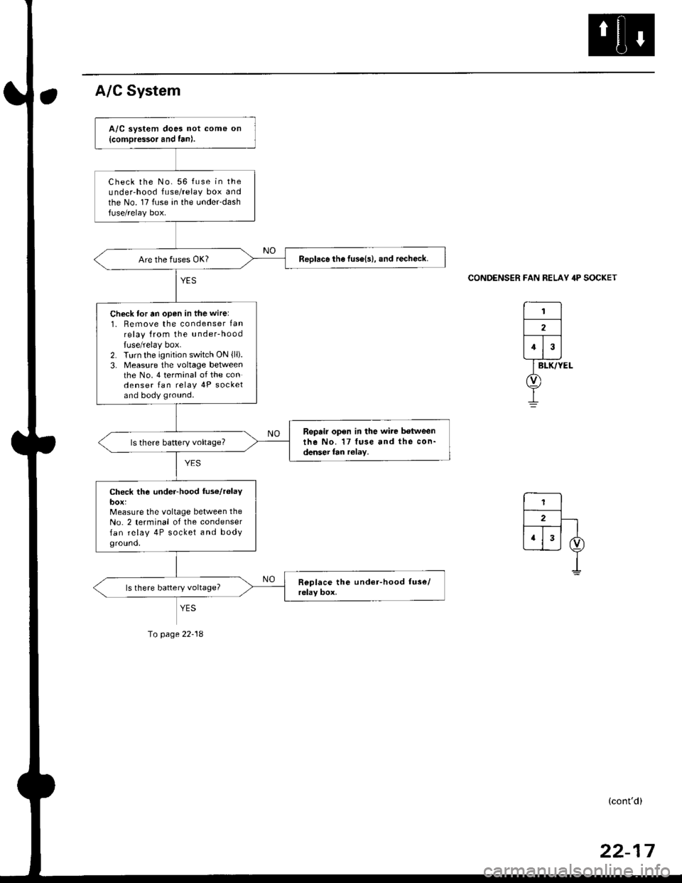
A/C System
CONDENSER FAN RELAY 4P SOCKET
A/C system does not come on
{comDressor and fan).
Check the No. 56 fuse in theunder'hood fuse/relay box andthe No. 17 fuse in the under-dashfuse/relay box.
ReDlace the fus6{s}, and recheck.
Check for tn open in the wire:
1. Remove the condenser lanrelay from the u nderhood
luse/relay box.2. Turn the ignition switch ON {lli.3- Measure the voltage betweenthe No. 4 terminal of the condenser fan relav 4P socketand body ground.
Repair open in the wire between
the No. 17 fuse and the con-denser fan r6lay,
Check the under-hood fus€/r6laybox:Measure the voltage between the
No. 2 terminal of the condenser
fan relay 4P socket and bodyground,
YES
Io page 22-18
(cont'd)
Page 1502 of 2189
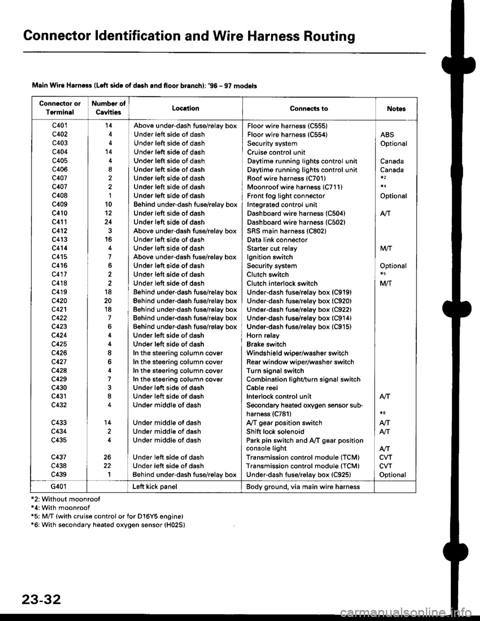
Connector ldentification and Wire Harness Routing
Connector or
Terminal
Number of
CavhiosLocationConnocts ioNotes
c401
c402
c403
c404
c405
c406
c407
c407
c408
c409
c410
c411
c412
c413
c414
c415
c416
c417
c418
c4l9
c420
c42'l
c423
c424
c425
c426
c427
c42A
c429
c430
c431
c432
c433
c434
c435
c431
c438
c439
'14
't4
I
I
10't2
24
16
7
o
18
20
18
7
6
I
o
4
7
8
14
1
Above under-dash fuss/relay box
Under left side ot dash
Under left sid€ of dash
Under left side of dash
Under left side of dash
Und€r left side of dash
Under left side of dash
Under left side of dash
Under left side of dash
Behind under-dash fuse/relay box
Under left side of dash
Under left side of dash
Above under-dash fuse/relay box
Under left side of dash
Under left side of dash
Above under-dash fuse/r€lay box
Under left side of dash
Under left side of dash
Under left side of dash
Behind under-dash fuse/relay box
Eehind under-dash fuse/relay box
Behind under-dash fuse/relay box
Behind under-dash fuse/relay box
Behind under-dash fuse/relay box
Under left side of dash
Under left side of dash
In the steering column cover
In the steering column cover
In the steering column cover
In the steering column covEr
Under left side of dash
Under left side of dash
Under middle of dash
Under middle of dash
Under middle of dash
Under middle of dash
Under left side of dash
Under left side of dash
Eehind under-dash fus€/relay box
Floo. wire harness (C555)
Floor wire harness (C554)
Security system
Cruise control unit
Daytime running lights control unit
Daytime running lights control unit
Roof wire harness (C701)
Moonroof wire harness (C7l1)
Front fog light connector
Integrated control unit
Dashboard wire harness (C504)
Dashboard wire harness (C502)
SRS main harness (C802)
Data link connector
Starter cut relay
lgnition switch
Security system
Clutch switch
Clutch interlock switch
Under-dash fuss/relay box (C9191
Undor-dash fuse/r€lay box {C920)
Under-dash tuse/relay box (C922)
Under-dash luse/relay box (C914)
Under-dash fuse/rBlay box (C915)
Horn relay
Brake swilch
Windshield wiper/washer switch
Rear window wiper/washer switch
Turn signal switch
Combination lighvturn signal switch
Cable reel
lnterlock control unit
Secondary heated oxygen sensor sub-
harn€ss (C781)
Ay'T gear position switch
Shift lock solenoid
Park pin switch and Ay'T gear position
console light
Transmission control module (TCM)
Transmission control module {TCM)
Under-dash fuse/relay box {C925)
ABS
Optional
Canada
Canada
Optional
Atr
MTT
Optional
Mlf
NT
Atf
CVT
CVT
Optional
AN
Atr
G401Left kick panelBody ground, via main wire harness
Main Wir€ Harness (Loft side of da3h and floor branch): '96 - 97 models
*2:Without moonroof*4: With moonroof*5: M/T (with cruise control or for D16Y5 engine)*6: With secondary heated oxygen sensor (H02S)
23-32
Page 1504 of 2189
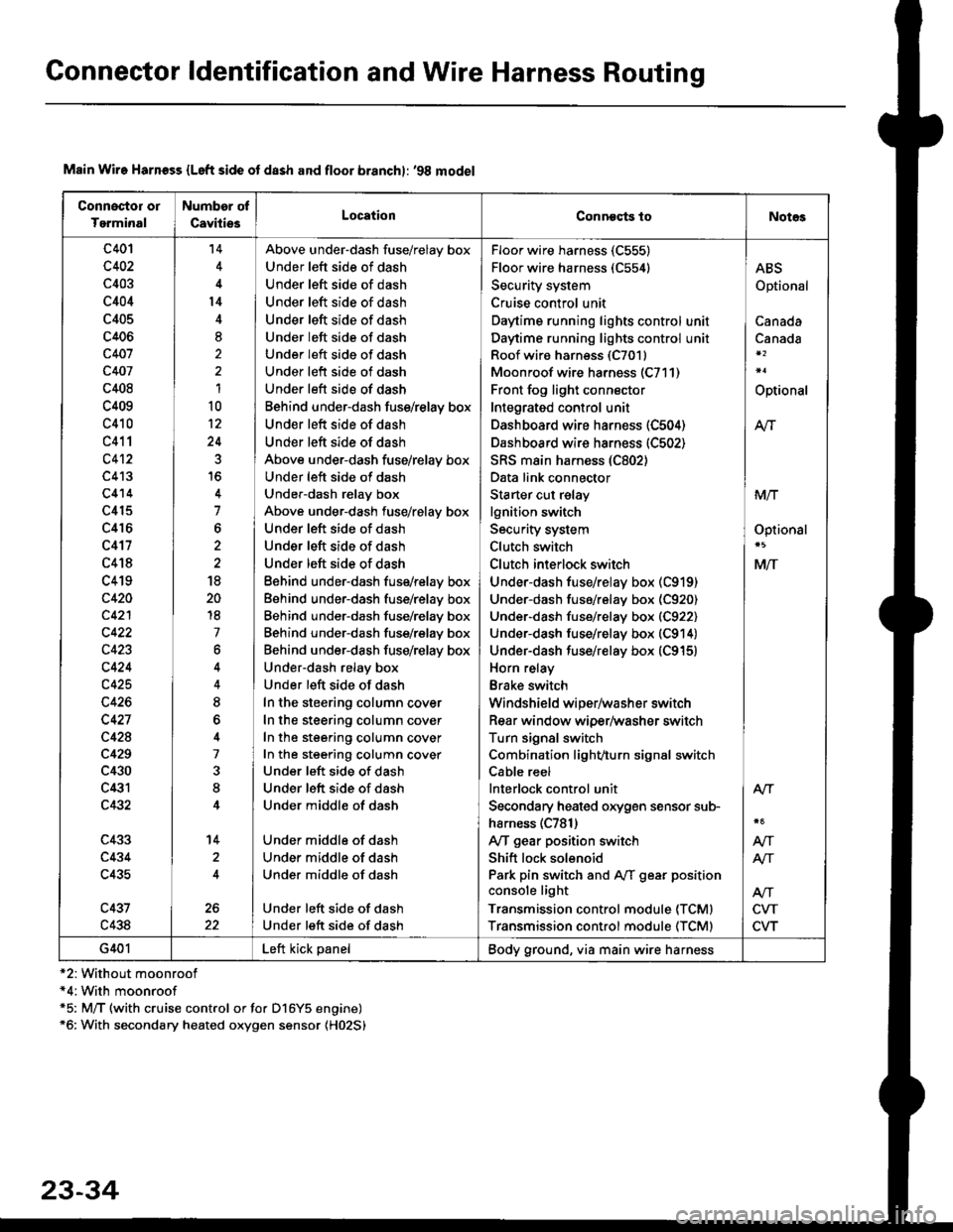
Connector ldentification and Wire Harness Routing
Connoctor or
Tgrminal
Number of
CavitiesLocationConneqts toNot€s
c401
c402
c403
c404
c405
c406
c407
c407
c408
c409
c410
c411
c4't2
c413
c414
c415
c416
c417
c418
c419
c420
c421
c422
c423
c424
c425
c426
c427
c428
c429
c430
c431
c432
c433
c434
c435
c437
c438
't4
l4
8,
1
10
12
24
7
6
18
20
18
7
6
8
7
8
14
2
Above under-dash fuse/relay box
Under left side of dash
Under left side of dash
Under left side of dash
Under left side of dash
Under left side of dash
Under left side of dash
Under left side of dash
Under left side of dash
Behind under-dash fuss/relay box
Under left side of dash
Under left side of dash
Above under-dash fuse/relay box
Under left side of dash
Under-dash relay box
Above under-dash fuse/relay box
Under left side of dash
Under left side of dash
Under left side of dash
Eehind under-dash fuse/relay box
Behind under-dash fuse/relay box
Behind under-dash fuse/relay box
Behind under-dash fuse/rslay box
Behind under-dash fuse/relay box
Under-dash relay box
Under left side of dash
In the steering column cover
In the steering column cover
In the steering column cover
In the steering column cover
Under left side of dash
Under left side of dash
Under middle of dash
Under middle of dash
Under middle of dash
Under middle of dash
Under left side of dash
Under left side of dash
Floor wire harness (C555)
Floor wire harness (C554)
Security system
Cruise control unit
Daytime running lights control unit
Daytime running lights control unit
Roof wiro harness (C7011
Moonroof wire harness (C711)
Front fog light connector
Integrated control unit
Dashboard wire harness (C504)
Dashboard wire harness (C502)
SRS main harness (C802)
Data link connector
Starter cut relay
lgnition switch
Security system
Clutch switch
Clutch inlerlock switch
Under-dash fuse/relay box (C919)
Under-dash fuse/relay box (C920)
Under-dash fuse/relay box (C922)
Under-dash fuse/relay box (C914)
Under-dash fuse/relay box (C915)
Horn relay
Brake switch
Windshield wiper/washer switch
Rear window wiper/washer switch
Turn signal switch
Combination light/,turn signal switch
Cable reel
lnterlock control unit
Secondary heated orygen sensor sub-
harness (C781)
Ay'T gear position switch
Shift lock solenoid
Park pin switch and Aff gear position
console light
Transmission control module (TCMI
Transmission control module (TCM)
ABS
Optional
Canada
Canada
Optional
M
MIT
Optionsl
MlT
Alr
NT
NT
CVT
CVT
G401Left kick panelBody ground, via main wire harness
Main Wire Harn€ss {Left side ot dash and floor branchl: '98 model
*2: Without moonroof*4:With moonroof*5: M/T (with cruise control or for D16Y5 engine)*6: With secondary heated oxygen sensor (H02S)
23-34