under-dash HONDA CIVIC 1998 6.G Repair Manual
[x] Cancel search | Manufacturer: HONDA, Model Year: 1998, Model line: CIVIC, Model: HONDA CIVIC 1998 6.GPages: 2189, PDF Size: 69.39 MB
Page 1729 of 2189
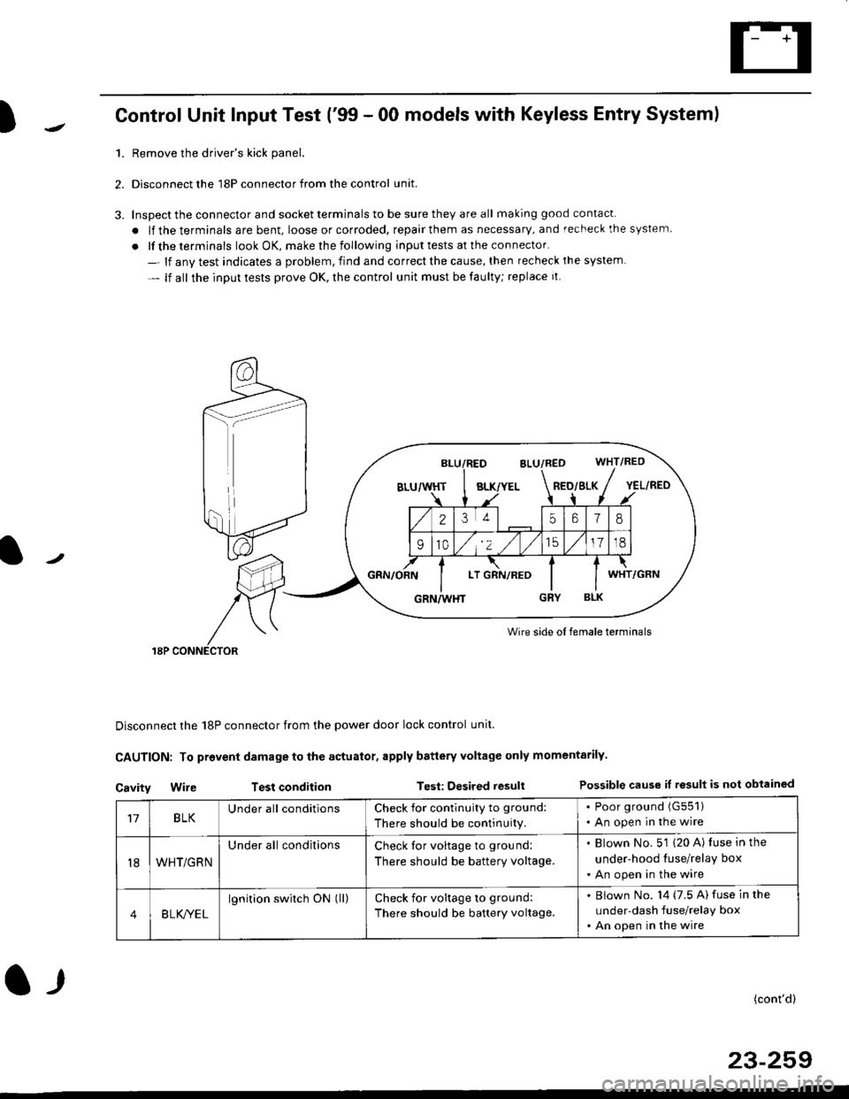
)Control Unit Input Test ('99 - 00 models with Keyless Entry System)
1.Remove the driver's kick panel.
Disconnect the 18P connector from the control unit.
Inspect the connector and socket terminals to be sure they are all making good contacl.
. lf the terminals are bent, loose or corroded, repair them as necessary, and recheck the system
. lf the terminals look OK, make rhe following input tests at the connector.
- lf anv test indicates a problem, find and correct the cause, then recheck ihe system
- lf all the input tests prove OK, the control unit must be faulty; replace it
Wire side oI female terminals
Disconnect the 18P connector from the power door lock control unit.
CAUTION: To provent damage to the actuator, apply battery Yoltage only momentarily.
Cavity Wir€ Test conditionTest: Desired resultPossible cause if result is not obtained
BLK/YELRED/SLK
25618
910/,'2 ,/
'151718
LTWHT
17BLKUnder all conditionsCheck for contlnuity to ground:
There should be continuity.
. Poor ground (G551)
. An open in the wire
t8WHT/GRN
Under all conditionsCheck tor voltage to ground:
There should be battery voltage.
. Blown No. 5'1 (20 A) luse in the
under-hood tuse/relay box
. An open in the wire
4B LK/YEL
lgnition switch ON (ll)check for voltage to ground:
There should be battery voltage.
Blown No. l4 (7.5 A) fuse in the
under-dash fuse/relay box
An open in the wire
(cont'd)
23-259
l-r
Page 1742 of 2189
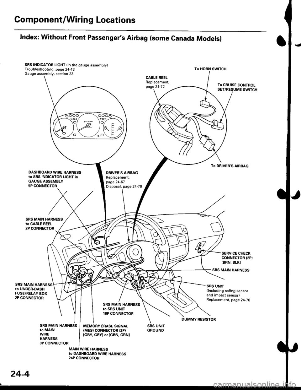
Gomponent/Wiring Locations
Index: Without Front Passenger's Airbag (some Canada Modelsl
SRS INDICATOR LIGHT (ln the gauge assembly)Troubleshooting, page 24-13Gauge assembly, section 23
DRIVER'S AIRSAGReplacement,page 24-67Disposal, page 24-70
SRS UNITGROUNO
To HORN SWITCH
SRS MAIN HARNESS
SRS UNIT{lncluding safing sensorand impact sensor)Replacement. page 24,76
To CRUISE CONTROLSET/RESUME SWITCH
oo/ \oo
To DRIVER,S AIRBAG
DASHBOARD WIRE HARNESSto SRS INDICATOR LIGHT inGAUGE ASSEMBLY5P CONNECTOR
SERVICE CHECKCONNECTOR {2P}IB8N, BLKI
SRS MAINto UNDER-DASHFUSE/RELAY BOX2P CONNECTOR
SRS MAIN HARNESSto SRS UNIT18P CONNECTOR
SRS MAIN HARNESSto MAINWIREHARNESS3P CONNECTOR
MEMORY ERASE SIGNAL(MES) CONNECTON (2P'
IGRY, GRYI o. IGRN, GRNI
MAIN WIRE HARNESSto DASHBOARD WIRE HARNESS24P CONNECTOR
24-4
DUMMY RESISTOB
Page 1763 of 2189
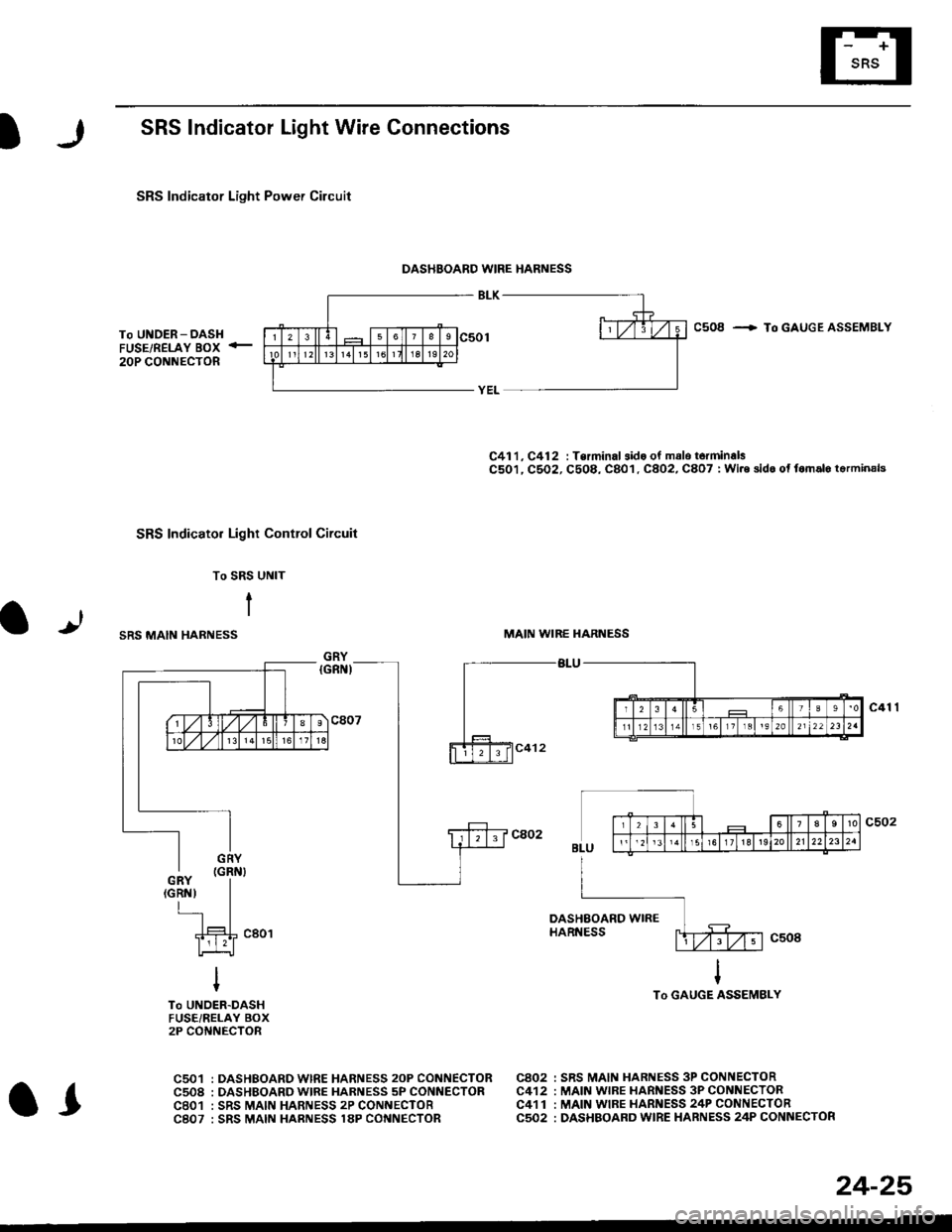
SRS Indicator Light Wire Connections
SRS Indicator Light Power Circuit
DASHBOARD WIRE HARNESS
To UNDER-DASHFUSE/RELAY BOX -
20P CONNECTOR
SRS Indicato. Light Control Circuit
To SRS UNIT
tI
SRS MAIN HARNESS
C41 1, C412 : Terminal sido of mdlo t6rminalsC501, C5O2, C508, C801. C802, C807 : Wi.6 sidc of fomalo t.rminals
MAIN WIBE HARNESS
BLU
C508 -+ To GAUGE ASSEMBLY
c41 1
To GAUGE ASSEMBLY
at
C501 : DASHBOARDWIRE HARNESS 2oP CONNECTORC508 : DASHBOARD wlRE HARNESS 5P CONNECTORC801 : SRS MAIN HARNESS 2P CONNECTORC807 : SRS MAIN HARNESS 18P CONNECTOR
C802 : SRS MAIN HARNESS 3P CONNECTORC412 : MAIN WIRE HARNESS 3P CONNECTORC41 1 : MAIN WIRE HARNESS 24P CONNECTORC502 : DASHBOARD WIRE HARNESS 24P CONNECTOR
GRY
OI
24-25
Page 1764 of 2189
Troubleshooting
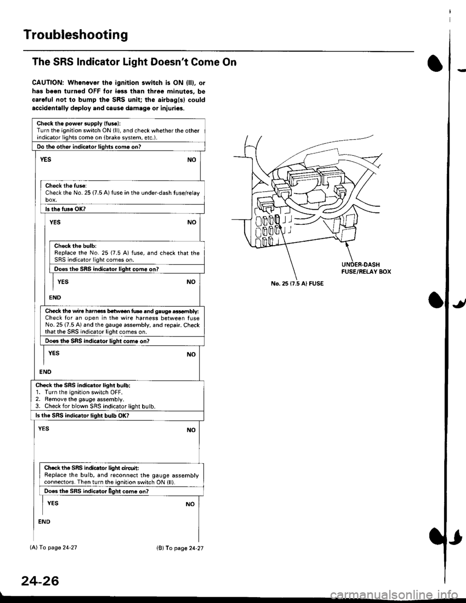
The SRS Indicator Light Doesn't Come On
CAUTION: Whonever ths ignition switch is ON {ll}, or
has been turned OFF tor less than three minutes. be
careful not to bump the SRS unit; the airbagls) could
accidentally deploy .nd caus6 damage or iniuri€s.
Check tho pow€r supply (fuse):
Turn the ignition switch ON (ll), and check whether the otherindicator lights come on (brake system, etc.).
Oo the other indicator liohts como on?
YESNO
Check th6 fuso:Check the No. 25 {7.5 A) fuse in the under-dash tuse/relayb"t
ls th6 tu36 OK?
NOYES
Check the bulb:Replace the No. 25 (7.5 A) fuse, and check that theSRS indicator light comes on.
Doos the SRS indicator liqhl come on7
I YES No
END
Check tho wire harns b€twecn fus6 and gauge aasambly:Check for an open in the wire harness between luseNo. 25 {7.5 A) and the gauge assembly, and repair. Checkthat the SRS indicator light comes on.
Doo. tho SRS indic.tor light como on?
I yEs No
I
END
Check tho SRS indicator light bulb:1. Turn the ignition switch OFF.2. Remove the gauge assembly.3. Check for blown SRS indicator light butb.
ls the SRS indicator light bulb OK?
NOYES
Ch.ck the SnS indicator liglrt circuit:Replace the bulb, and reconnect the gauge assemblyconnectors. Then turn the ignition switch ON {ll}.
Ooes th6 SRS indicato. llght come on?
I YEs No
:ND
lAl To page 24-27
24-26
lB'J fo page 24-27
))
No. 25 (7.5 Al FUSE
Page 1777 of 2189
.J
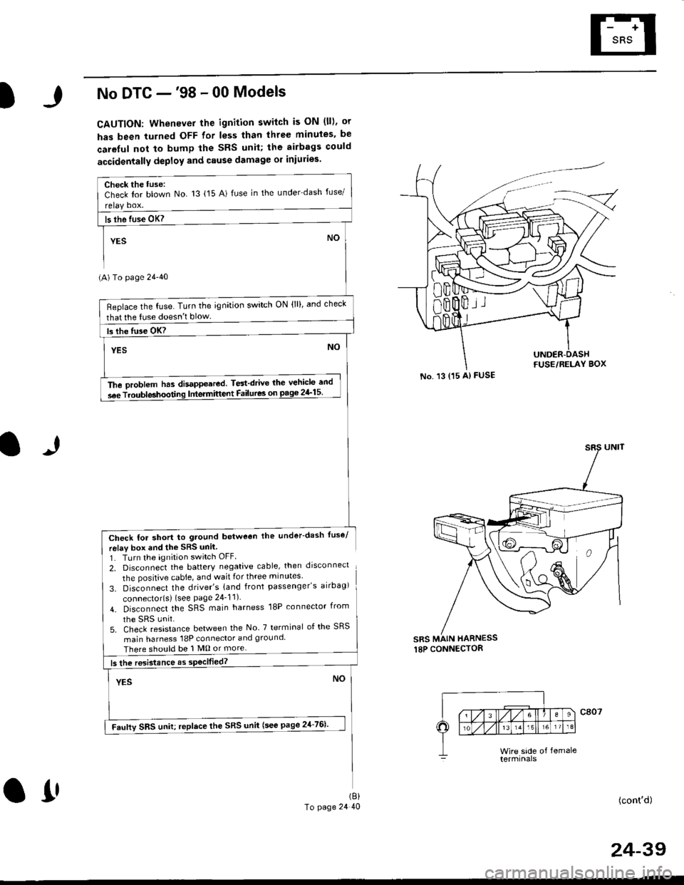
No DTC -'98 - 00 Models
CAUTION: Whenever the ignition switch is ON (ll), or
has been turned OFF for less than three minuies. be
careful not to bump the SRS unil; the airbags could
accidentally deploy and cause damage or iniuries
(A) To page 24'40
Check for short to ground betweon the under-dash fuse/
relav box end the SRS unil
1. TLrrn the ignition switch OFF
2, Disconnect the battery negative cable, then drsconnect
the positive cable, and wait for three minutes'
3. Disconnect the driver's {and front passenger's airbag)
connector{s) {see Page 24_11)
4. Disconnect the SRS main harness 18P connector irom
5. Check resistance between the No 7 terminal of the SRS
main harness 18P connector and ground
There should be 1 M0 or more
(cont'd)
No. 13 {15 A) FUSE
sRs MAIN HARNESS
Check the tuse:Check Ior blown No 13 {15 A) fuse in the under dash fuse/
Beplace the fuse. Turn the ignition switch ON (lll, and check
that lhe tuse doesn't blow
The oroblem has disappeared. Test'drive thc vehicle and
s6e Troubleahoodng lntermittent Failures on pago 2&15
Faufty SRS uniu replace the SRS unii (see page 21-761'
(8)
To page 24 40O1'
24-39
Page 1778 of 2189
Troubleshooting
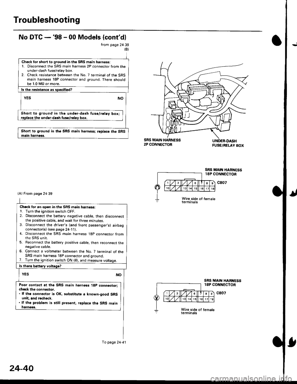
No DTG -'98 - 00 Models (cont'dl
trom page 24 39
SRS MAIN HARNESS2P CONNECTOB
SRS MAIN HARTESS18P CONNECTOR
FUSE/RELAY BOX
c807
c807
Wir€ side ot fsmaleterminals
SRS MAIN HAR ESSlAP CONNECTOR
(Bi
Check for short to ground in iho SRS main ha.no$:1. Disconnect the SRS main harness 2P connector from theunder-dash fuse/relay box.2. Check resistance between the No. 7 terminal of the SFSmain harness 18P connector and ground. There shouldbe 1.0 MO or more.
ls lha r6i3tlnce as sp.cilied?
YESNO
Short to ground in the und..-d.sh tu3a/r.lay box;roplace the undsr-dlrh tu!6/rahy box.
Short to ground in fho SRS main harness; rsplecc the SRSmain htrnors.
Check lor an open in the SRS main harn€ls:1- Turn tho ignition switch OFF.2. Disconnect the baftery negative cable, then disconnectthe positive cable, and wait for three minutes.3. Disconnect the driver's (and front passenger's) airbagconnector(sl (see page 24-11).4. Disconnect the SBS main harness 18P connector tromthe sRs unit.5. Reconnect the battery positive cable, then reconnect thenegative cable.6. Connect a voltmeter between the No. 7 terminal ol theSFS main harness 18P connector and qro!nd.7. Turn the ignition switch ON (ll), and measure
Poor contact rt the SRS main harness 18P conn.ctor:chock th€ connectoi.. ll th. connector is OK, iubstitute a known-good SRSunit, and recheck.. lf tho pioblem is still pres6nt. replace the SRS mlinhaanos3.
(A) From page 24 39
To page 24.41
24-40
Page 1779 of 2189
)
From page 24-40
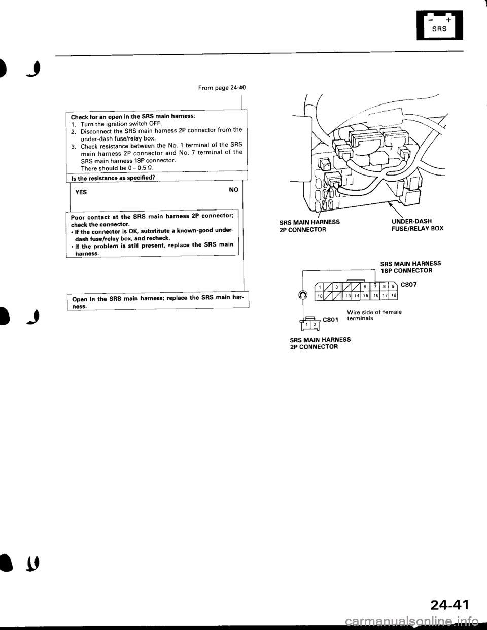
Check for an open in the SRS main harn6s:
1. Turn the ignition switch OFF.
2. Disconnect the SRS main harness 2P connector from the
under-dash fuse/relay box
3. Check resistance between the No. 1 terminal ol the SRS
main harness 2P connector and No. 7 terminal of the
SRS main harness 18P connector.
Thereshouldbe0 05O
ls the resistance es specitied?
YES
Poor contact at the SRS main hatness 2P connector;
check the connector-. It the connector i3 OK, substitute a known-good und€r-
dash fuse/relav box, and recheck..ll the Droblem i5 still pres€nt, replace lhe SRS main
harness.
NO
Open in the SRS main hsrness; leplaco the SRS main har-
ness.
)
FUSE/RELAY BOX
SRS MAIN HARNESS18P CONNECTOR
c807
Wire side of femaleterminals
SRS MAIN HARNESS2P CONNECTOR
24-41
lrt
Page 1803 of 2189
)
FUSE/BELAY BOX
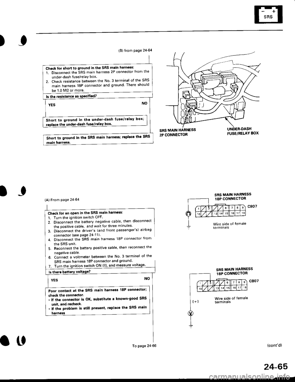
Chcck for an op€n in th6 SRS main harness:
1. Turn the ignition switch OFF.
2. Disconne;t the battery negative cable, then disconnect
the positive cable, and wait for three minutes'
3. Disconnect tho driver's (and front passenger's) airbag
connector (see Page 24'11).
4. Disconnect the SRS main harness 18P connector from
the SRS unit
5. Reconnect the battery positive cable, then reconnect the
neoative cable.
6. Co-nnect a voltmeter betlveen the No 3 terminal ol the
SFS main harness 18P connector and ground'
7. Turn theswitch ON (ll), and m€asure
(cont'd)
(B) from page 24-64
Check tor ahort to ground in the SRS main harn$s:
1. Disconnect the SRS main harness 2P connector from the
under-dash fuse/relaY box.
2. Check resistance between the No. 3 terminal of the SRS
main harness 18P connector and ground There should
be 1.0 M0 or more.
ls the re3istance a3 specified? -
NOYES
Short to giound in tho undot-drlh lut'/rol'y box;
replace the undel-da3h fusgtgEl!9l--------.-
Short to ground in tho SRS m.in harn$s; ropleco the SRS
main harness.
(AlFrom page 24'64
Poor contact at the SRS main harnoss 18P connoctor;
check lho connoctor.. ll the connector k OK, sub3titute r known'good SRS
unh. and recheck. lf the problom is slill present, lepl.ce the SRS main
To page 24-66
SRS MAIN HARNESS18P CONNECTOR
o0
24-65
Page 1804 of 2189
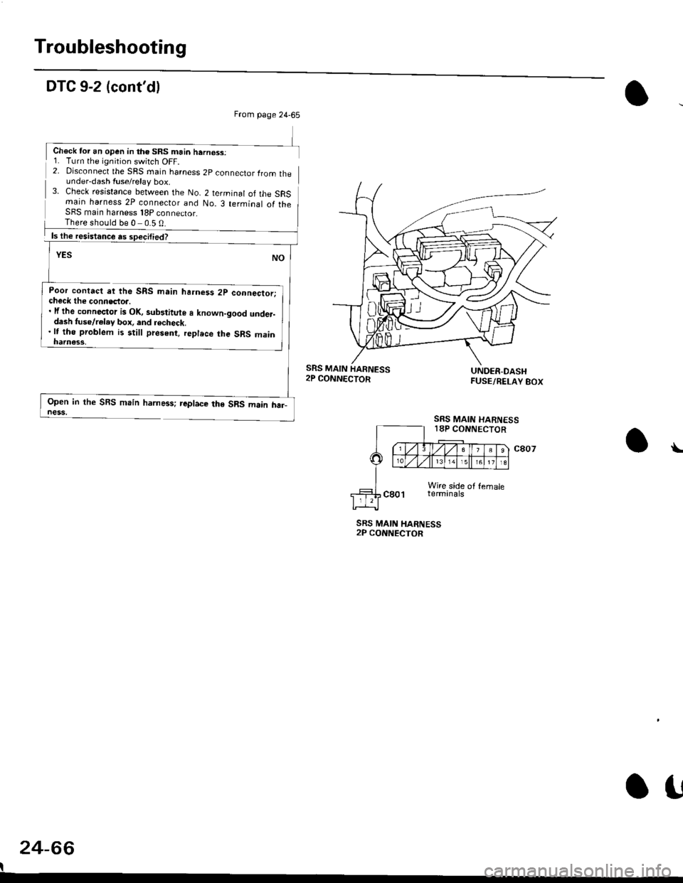
Troubleshooting
DTC 9-2 (cont'dl
2- Disconnect the SRS rnain harness 2p connector lrom theunder-dash fuse/relay box.3- Check resistance between the No. 2 terminal of the SRSmain harness 2P connecior and No. 3 terminal of theSFS main harness 18P connector_
Poor contact at the SRS main ha.ness 2p connector;check the connecto... lf the connector is Ol(, sub3titute a known-good under-dash tuse/r€lay box, and recheck.'lt tho problem is still present, replece the SRS main
Open in the SBS main harness; replace the SRS main har_ness,
SRS MAIN HARNESS2P CONNECTOR
24-66
I
\
From page 24-65
Chock tor an open in th€ SRS main hern€ss:1. Turn the ignition switch OFF.
There should be 0 0.5 0
SRS MAIN
SRS MAIN HARNESS18P CONNECTOR
o!
Page 1817 of 2189
Contents
How to Use This Manual ICircuit Schematics (see Circuit Index)Fuse/Relaylnformation 6Ground-to-Componentslndex 6-6ComponentLocationPhotooraohs 201Conriector Views 202
Circuit Index
Accessory power socket 155Air conditionerAir delivery'96198 models 61'99-'00 models 61-2Blower controls'96198 models 60'99100 models 60-1Compressor controls 62Fans 63Anti-lock brake system (ABS) 44A/T gear position indicatorCVT 89All except CVT 89-1Automatic transmission controlsAll '96-'98 models except CVT and GX 39All '99100 models except CVT 39-8All GX models 39-8'96-'98 CVT 39-4'99100 cw 39-12Back-up lightsCoupe and Sedan 110Hatchback l'10-1Brake lightsAll Coupes and'96-'98 Sedans 110-15'99-'00 Sedans 110-16Hatchback 110-17Brake system indicator light'96198 models 7'1'99100 models 71-1Ceiling light 114-3Charging system 22Condenser fan 63Console lights 114Cruise control 34Dash lights 114Daytime running lights 110- 13Engine coolant temperature gauge 81-1Fog lights 110-10Front parking lights 110-2Fuel gauge 81-1Fuse/relay boxUnder-dash 6Under-hood 6-4Underhood ABS 6-3Gauges 81Ground distribution 14Ground-to-Componentslndex 6-6Hazard warning lightsAll except '99100 Sedans 110-6'99100 Sedans 110-8Headlights 110-12Headlight switch 100Heater - See Air ConditionerHorn'96197 models 40'98 model 40-1'99100 models 40-2lgnition key reminder 73lgnition systemAll '96198 models except Dl685 20All '99100 models except D16Y5 with Mn 2O-2All D1685 engines 20-2'99-'00 D 16Y5 with M/T 20
lndicators 80Integrated control unit 70lnterlock systemAll except'96J98 CVT 138'96198CVT 138-1License plate lightsAll Coupes and '96-'98 Sedans I l0-3'99100 Sedans 1 10-4Hatchback 110-5Low fuel indicator light 74Moonrool'96197 models |22'98-'00 models 122-1Odometer 81Oil pressure indicator light 80-3Power distributionBattery to ignition switch, fuses, and relaysFuses to relays and components 10-2Power door locksAll models without keyless entry 130'96-'98 models with keyless entry 130-2'99100 models with keyless entry 130-12Power mirrorsWithout detogger 141With defogger '141-2
Power windows 120Programmed fuel injection system (PGNr-Fl)All '96-98 models except D1685 23All '99-'00 models except D16Y5with M/T and D1685 24All D1685 engines 25'99100 D16Y5 with M/T 23Radiator fan 63Rear window defogger'96-,98 models 64'99100 models 64-1Seat belt reminder 73Security system'96.'98 USA HX, LX, EX 133'96-'98 Canada EX, Si 133'99TOO USA HX, LX, EX, DX.V Si 133-4'99100 Canada EX, Si 133-4All CX and DX models 133-8Speedometer 81Starting systemA./T (All except Dl685) 21A"/r (D16Bs) 21-1Manualtransmission 21-2Slereo sound system 150Supplemental rastraint system (SRS) 47Tachometer 81TailliqhtsAllboupes and'96-'98 Sedans 110-3'99100 Sedans 1 10-4Hatchback 110-5Trunk light 114-3Turn signal lightsAll except'99100 Sedans 110-6'99-'00 Sedans 1 10-8Vehicle speed sensor (VSS) 33Wiper/washerFront 91Rear 92
10