under-dash HONDA CIVIC 1998 6.G Owner's Guide
[x] Cancel search | Manufacturer: HONDA, Model Year: 1998, Model line: CIVIC, Model: HONDA CIVIC 1998 6.GPages: 2189, PDF Size: 69.39 MB
Page 1559 of 2189
lgnition Switch
4.
Test
SRS components are located in this area Review the
SRS component locations. precautions. and procedures
in the SRS section {24} before performing repairs or ser-
1. i/ake sure you have the anti-theft code for the
radio, then write down the frequencies for the
radio's preset buttons ('99 - 00 models).
2. Disconnect the battery negative cable.
3. Remove the driver's dashboard lower cover and
knee bolster (see section 20).
Disconnect the 5P connector from the under dash
fuse/relay box and the 7P connector from the main
wire harness.
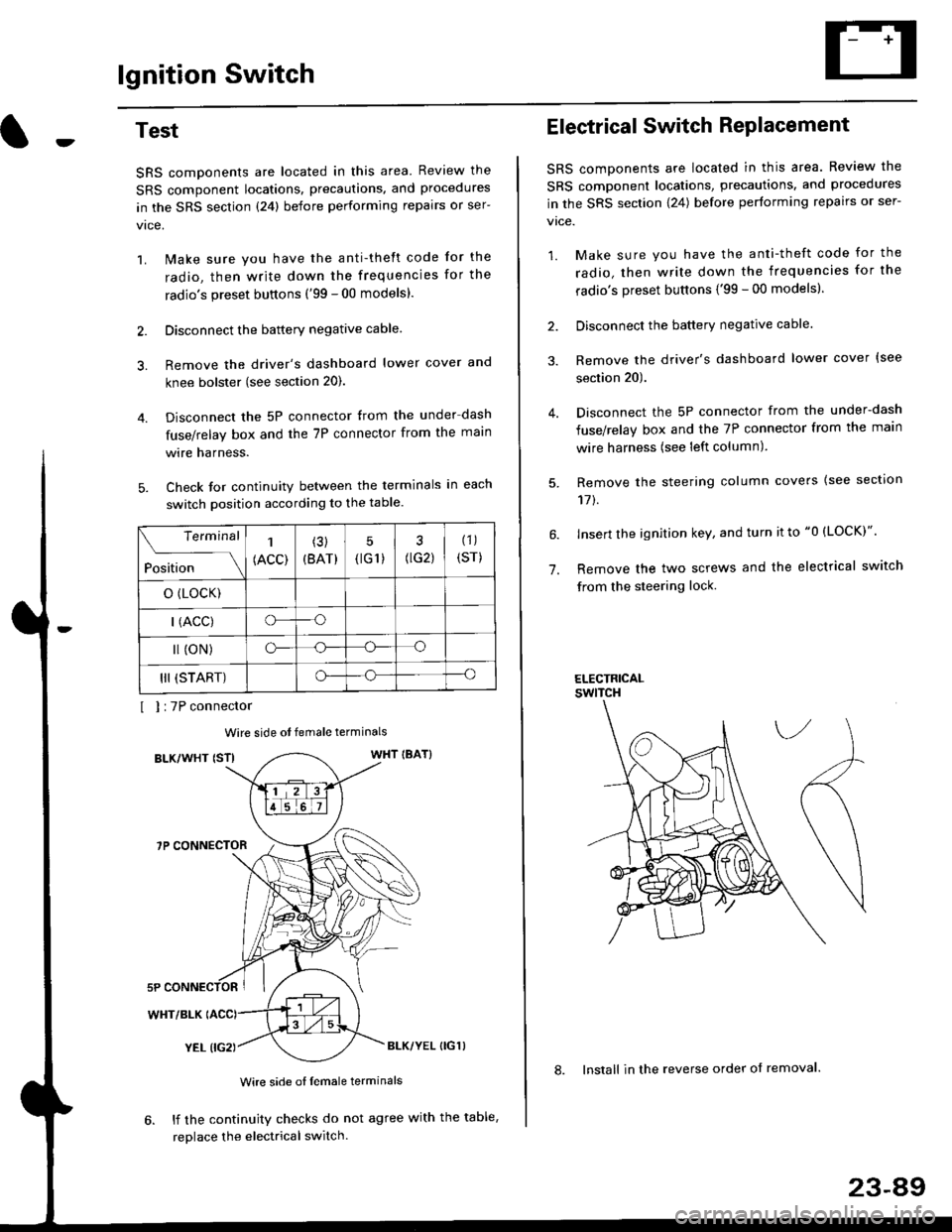
Check for continuity between the terminals in each
switch position according to the table.
I I :7P connector
Wire side ot female terminals
BLK/WHT {STIWHT IBAT}
7P CONNECTOR
WHT/BLK
YEL (IG2}BLK/YEL {IG1)
Wire side of female terminals
6. lf the continuity checks do not agree with the table,
replace the electrical switch.
Terminal
Position
1
(ACC)
(3)
(BAT)
5
{tG1) G2)
(1)
(sr)
o (LocK)
| (ACC)o--o
l (oN)o-o
III (START)o--o
1.
Electrical Switch RePlacement
SRS components are located in this area. Review the
SRS component locations, precautions, and procedures
in the SRS section \24) belore performing repairs or ser-
vtce.
1. Make sure you have the anti-theft code for the
radio, then write down the frequencies for the
radio's preset buttons {'99 - 00 modelsl.
2. Disconnect the battery negatlve cable.
3. Remove the driver's dashboard lower cover {see
section 20).
Disconnect the 5P connector from the under-dash
fuse/relay box and the 7P connector from the main
wire harness (see left column).
Remove the steering column covers {see section
11t.
lnsert the ignition key, and turn it to "0 {LOCK)".
Remove the two screws and the electrical switch
from the steering lock.
ELECTRICALswtTcH
8. Install in the reverse order of removal.
23-a9
Page 1560 of 2189
lgnition Switch
Steering Lock Replacement
SRS components are located in this area. Review theSRS component locations. precautions, and procedures
in the SRS section (24) before performing repairs or ser-vtce.
Remove:
LMake sure you have the anti-theft code for theradio, then wire down the frequencies for theradio's preset buttons ('99 - 00 models).
Disconnect the battery negative cable.
Remove the driver's dashboard lower cover andknee bolster (see section 20).
Disconnect the 5P connector from the under-dash
fuse/relay box and the 7P connector from the mainwire harness (see previous page).
Remove the steering column covers, then removethe mounting bolts and nuts from the steering col-umn (see section l7).
Lower the steering column assembly,
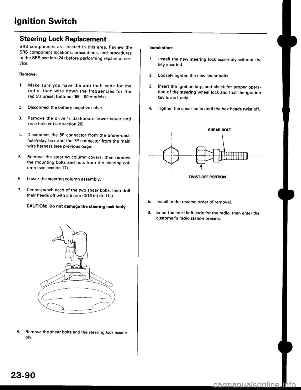
Center-punch each of the two shear bolts, then drilltheir heads off with a 5 mm (3/16 in) dritt bit.
CAUTION: Do not damago the steering lock body.
Remove the shear bolts and the steering lock assem,oty.
2.
1.
23-90
Installation:
l. Install the new steering lock assembly without thekey insened.
Loosely tighten the new shear bolts-
Insert the ignition key, and check for proper opera-tion of the steering wheel lock and that the ignitionkey turns freely.
Tighten the shear bolts untilthe hex heads twist off.
TWIST.OFF FORTION
Install in the reverse order of removar.
Enter the anti-theft code for the radio, then enter thecustomer's radio station presets.
sr{€aR SroLT
Page 1579 of 2189
Jlgnition Control Module (lCMl Input Test
NOTE:
. See section 1'l when the malfunction indicator lamp
(MlL) turned on.
. Perform an input test for the ignition control module
(lCM) after finishing the fundamental tests for the
ignition system and the fuel and emissions systems
1. Remove the distributor ignition (Dl) cap, the distrib-
utor ignition (Dl) rotor and the leak cover (TEC).
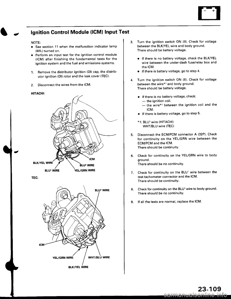
2. Disconnect the wires from the lCM.
HITACHI:
BLK/YEL
TEC:
Turn the ignition switch ON (ll). Check for voltage
between the BLK/YEL wire and body ground.
There should be battery voltage.
. lf there is no battery voltage, check the BLK/YEL
wire between the under-dash fuse/relay box and
rhe lcM.
. lf there is battery voltage, go to step 4.
Turn the ignition switch ON (ll). Check for voltage
between the wire*r and body ground
There should be battery voltage.
. lfthere is no battery voltage, check:
- the ignition coil.
- the wire*1 between the ignition coil and the
tcM.
. lf there is battery voltage, go to step 5
*1: BLU'wire (HITACHI)
WHT/BLU wire (TEC)
Disconnect the EcM/PCM connector A (32P). Check
for continuity on the YEUGRN wire between the
ECM/PCM and the lCM.
There should be continuity.
Check for continuity on the YEUGRN wire to body
ground.
There should be no continuity.
Check for continuity on the BLUl wire between the
test tachometer connector and the ICM
There should be continuitY.
Check for continuity on the BLUl wire to body ground.
There should be no continuity.
lf all the tests are normal, replace the ICM
7.
23-109
Page 1610 of 2189
Vehicle Speed Sensor (VSSI
Troubleshooting
Before testing, inspect the No. 15 (7.5 A) fuse in the under-dash fuse/relay box.
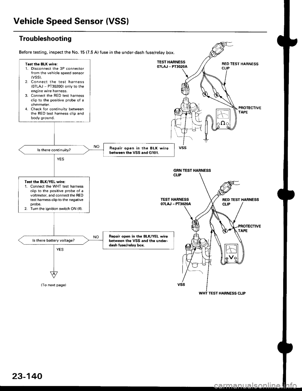
TEST HARNESSOTLAJ _ PT3O2OAREO TEST HARNESSCLIP
PROTECTIVETAPE
TEST HARNESSOTLA' . PT3O2OA
(To next page)
Test the BLK wire:1. Disconnect the 3P connectorfrom the vehicle speed sensor(vss).
2. Connect the test harness(07LAJ PT30200) only to theengine wire harness,3. Connect the RED test harnessclip to the positive probe of a
4. Check for continuity betweenthe RED test harness clip andbody ground.
Repair opon in the BLK wireb€twe€n the VSS and G101.ls there continuity?
Te3t the BLK/YEL wire:1. Connect the WHT test harnessclip to the positive probe of avoltmeter, and connectthe REDtest harness clip to the negativeprobe.2. Turn the ignition switch ON {ll).
Repair open in iho BLK/YEL wirebetween the VSS and the under-d6sh tuse/relav box.
vss
GRN TEST HARNESS
RED TEST HARNESS
WHT TEST HARNESS CLIP
23-140
Page 1612 of 2189
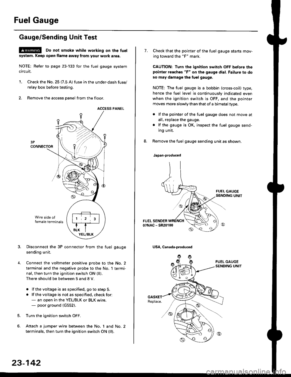
Fuel Gauge
Gauge/Sending Unit Test
!@ Do not smoke while working on tho fuel
system. Keep open tlame away trom your wotk atea.
NOTE: Refer to page 23-133 for the fuel gauge system
circuit.
'1. Check the No. 25 (7.5 A) fuse in the under-dash fuse/
relay box before testing.
2. Remove the access panel from the floor.
ACCESS PANEL
Disconnect the 3P connector from the fuel gauge
sending unit.
Connect the voltmeter positive probe to the No. 2
terminal and the negative probe to the No. I termi-
nal, then turn the ignition switch ON (ll).
There should be between 5 and 8 V.
. lf the voltage is as specified, go to step 5.
. lf the voltage is not as specified. check for:- an open in the YEUBLK or BLK wire.- poor ground (G552).
Turn the ignition switch OFF.
Attach a jumper wire between the No. 1 and No. 2
terminals, then turn the ignition switch ON (ll).
)\
23-142
1.Check that the pointer of the fuel gauge starts mov-
ing toward the "F" mark.
CAUTION: Turn the ignition switch OFF before thepoinier reaches "F" on ihe gauge dial. Failure to do
so may damage the fuel gauge.
NOTE: The fuel gauge is a bobbin (cross-coil) type,
hence the fuel level is continuously indicated even
when the ignition switch is OFF, and the pointer
moves more slowly than that of a bimetaltype.
. lf the pointer of the fuel gauge does not move at
all, replace the gauge.
. lf the gauge is OK. inspect the fuel gauge send-
ing unit.
Remove the fuel gauge sending unit as shown.
Japan-produced
USA, Canada-produced
Page 1616 of 2189
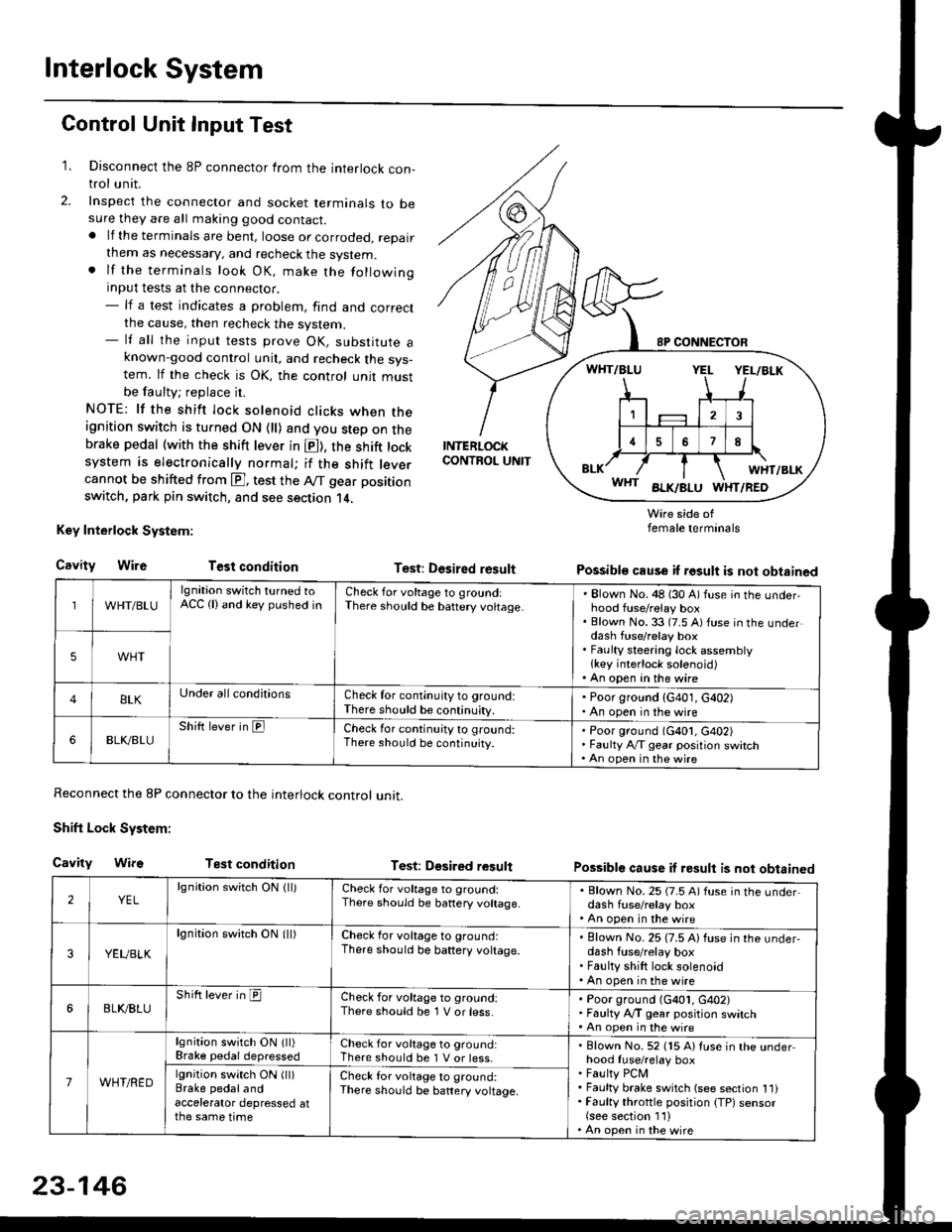
Interlock System
Control Unit Input Test
1. Disconnect the 8P connector from the interlock con-trol unit.
2. Inspect the connector and socket terminals to besure they are all making good contact.. lf the terminals are bent, loose or corroded, repairthem as necessary, and recheck the system.. lf the terminals look OK, make the followinginput tests at the connector.- lf a test indicates a problem, find and correctthe cause, then recheck the system.- lf all the input tests prove OK, substitute aknown-good control unit, and recheck the sys-tem. lf the check is OK, the control unit mustbe faulty; replace it.
NOTE: lf the shift lock solenoid clicks when theignition switch is turned ON {ll) and you step on thebrake pedal (with the shift lever in E), the shift locksystem is electronically normal; if the shift leve.cannot be shifted from E], test the Aff gear position
switch, park pin switch, and see section 14.
Key Interlock System:
CavityWireTest condition
Reconnect the 8P connector to the interlock control unit.
Shift Lock System:
Cavity WifsTest condition
INTERLOCKCONTROL UNIT
Test: Desired result
Test: Dgsired result
Wire side offemale terminals
Possible cause if result is not obtained
Possible cause if result is not obtained
WHT/BLU
lgnition switch turned toACC (lland key pushed inCheck for voltage to groundiThere should be baftery voltage.Blown No. 48 (30 A) fuse in the underhood fuse/relay boxBlown No. 33 (7.5 A) fuse in the underdash fuse/relay boxFaulty steering lock assemblylkey interlock solenoid)An open in the wire
5WHT
BLKUnder all conditionsCheck for continuity to ground:There should be continuity.
' Poor ground (G401, G402). An open in the wire
6BLK./BLUShift lever in ElCheck for continu;ty to ground:There should be continuity.Poor ground (G401, G402)Faulty Ay'T gear position switchAn open in the wire
2YELlgnition switch ON lll)Check for voltage to ground:There should be banery voltage.
. Blown No. 25 (7.5 A) fuse in the under,dash fuse/relay box. An open in the wire
3YEUBLK
lgnition swirch ON (ll)Check for voltage to ground:There should be baftery voltage.Blown No. 25 (7.5 A) fuse in the under-dash fuse/relay boxFaulty shift lock solenoidAn open in the wire
6BLI(BLUShift lever in ICheck for voltage to ground:There should be 1 V or less.Poor ground (G401, G402)Faulty A,/T gear position switchAn open in the wire
7WHT/RED
lgnition switch ON lll)Brake pedaldepressedCheck for voltage to ground:There should be 1 V or less.Blown No. 52 (15 A) Iuse in the underhood fuse/relay boxFaulty PCMFaulty brake switch (see section 1l)Faulty throttle position {TP) sensor(see section 1'l )An open in the wire
lgnition switch ON (ll)Brake pedalandaccelerator depressed atthe same time
Check for voltage to ground:There sho(Jld be battery voltage.
23-146
Page 1623 of 2189
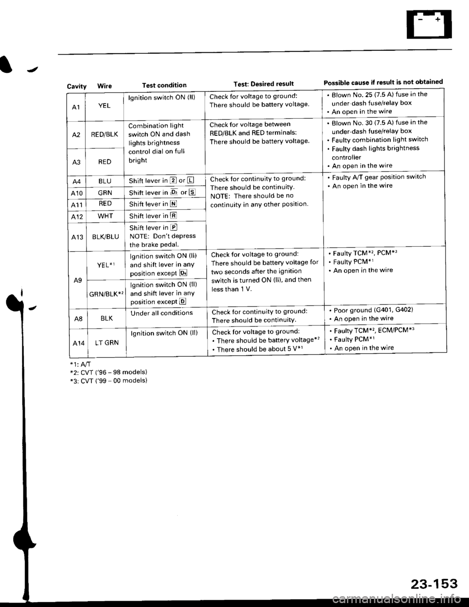
Test conditionTest: Desired resultPossible cause it result is not obtainedCavity
AIYEL
lgnition switch ON (ll)Check for voltage to ground:
There should be banerY voltage.
. Blown No.25 (7.5 A) fuse in the
under dash fuse/relay box
. An open in the wire
A2RED/BLK
Combination light
switch ON and dash
lights brightness
control dial on full
bright
Check for voltage between
RED/BLK and RED terminals:
There should be batterY voltage.
Blown No. 30 {7.5 A) fuse in the
under-dash tuse/relay box
Faulty combination light switch
Faulty dash lights brightness
controller
An open in the wireA3RED
BLUShift lever in P or ICheck for continuity to ground:
There should be continuitY
NOTE: There should be no
continuity in anY other Position.
. Faulty A/T gear Position switch
. An open in the wire
A10GRNShift lever in E or E
A11REDShift lever in E
412WHTShift lever in E
A13BLK/BLU
Shift lever in E
NOTE: Don't depress
the brake pedal.
A9
YEL+ ]lgnition switch ON (ll)
and shift lever in any
position except Pi
Check for voltage to ground:
There should be battery voltage for
two seconds after the ignition
switch is turned ON (ll), and then
less than 'l V.
Faulty TCM*', PCM*3
Faulty PCM*r
An open in the wire
GRN/err*'
lgnition switch ON {ll)
and shift lever in anY
position except E
A8BLKUnder all conditionsCheck for continuitv to ground:
There should be continuitY.
. Poor ground (G401, G402)
. An open in the wire
414LT GRN
lgnition switch ON (ll)Check for voltage to ground:
. There should be baftery voltage*'
. There should be about 5 V*r
Faulty TCM*', ECM/PCM*'
Faulty PCM*1
An open in the wire
*2: CVT ('96 - 98 models)*3r CVT ('99 - 00 modelsl
23-153
Page 1629 of 2189
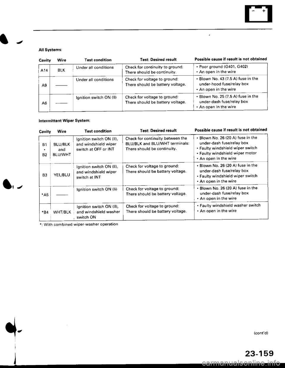
All Systems:
Cavity Wire
Cavity Wire
Intelmittent Wiper System:
Test condilion
Test condition
Test: Desired resultPossible cause il rgsull is not obtained
Test: Desired resultPossible cause if result is not obtained
Al4BLKUnder all conditionsCheck for continuity to ground:
There should be continuity.
. Poor ground (G401, G402). An open in the wire
A9
Under all conditionsCheck for voltage to ground:
There should be battery voltage.
. Blown No. 43 (7.5 A) fuse in the
under-hood fuse/relay box
. An open in the wire
A6
lgnition switch ON (ll)Check for voltage to ground:
There should be baftery voltage.
. Blown No. 25 (7.5 A) fuse in the
under-dash fuse/relay box. An open in the wire
B1
82
BLU/BLK
and
BLU,^/VHT
lgnition switch ON (ll),
and windshield wiper
switch at OFF or INT
Check for continuity between the
BLU/BLK and BLU/WHT terminals:
There should be continujty.
Blown No. 26 {20 A) fuse in the
under-dash fuse/relay box
Faulty windshield wiper switch
Faulty windshield wiper motor
An open in the wire
B3YEUBLU
lgnition switch ON (ll),
and windshield wiper
switch at INT
Check for voltage to ground:
There should be battery voltage.
Blown No.26 (20 A) fuse in the
under-dash fuse/relay box
Faulty windshield wiper switch
An open in the wire
*A5lgnition switch ON (ll)Check tor voltage to ground:
There should be battery voltage.
. Blown No.26 (20 A) fuse in the
under-dash fuse/relay box. An open in the wire
WHT/BLK
lgnition switch ON { ll),
and windshield washer
switch ON
Check for voltage to ground:
There should be battery voltage.
. Faulty windshield washer switch
. An open in the wire
*: With combined wiper'washer operatlon
{-(cont'd)
Page 1630 of 2189
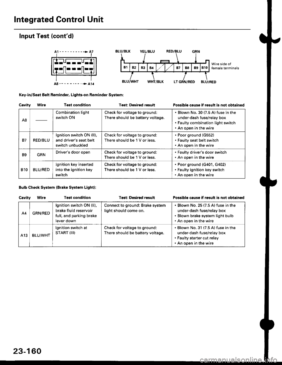
Integrated Gontrol Unit
Input Test (cont'dl
A8--------.--all
Key-in/Seat Belt R€mind€r, Lights-on Reminder Systom:
Cavity WireTest condhion
Bulb Check System (Brako System Light):
Cavity WireTest condilion
Tost: D€sirod r€guh
T6st: Dosirad result
Possible cause if result is not obtained
Possibls cause if rasuft b not obtainod
A8
Combination light
switch ON
Check for voltage to ground;
There should be battery voltage.
Blown No.30 (7.5 A)fuse in the
under-dash fuse/relay box
Faulty combination light switch
An open in the wire
B7RED/BLU
lgnition switch ON (ll),
and driver's seat belt
switch unbuckled
Check for voltage to ground:
There should be 1 V or less.
Poor ground (G552)
Faulty seat belt switch
An open in the wire
B9GRNDriver's door openCheck for voltage to ground:
There should be 1 V or less.
. Faulty driver's door switch. An open in the wire
Bl0BLU/RED
lgnition key inserted
into the ignition key
switch
Check for voltage to ground:
There should be 1 V or less.
Poor ground (G401. G402)
Faulty ignition key switch
An open in the wire
A4GRN/RED
lgnition switch ON {ll),
brake fluid reservoir
full, and parking brake
tever oown
Connect to ground: Brake system
light should come on.
Blown No.25 (7.5 Alfuse in the
under-dash fuse/relay box
Blown brake system light bulb
An open in the wire
A13BLUA/1r'HT
lgnition switch at
START (III)Check for voltage to ground:
There should be battery voltage.
Blown No.31 (7.5 A) fuse in the
under-dash fuse/relay box
Faulty starter cut relay
An open in the wire
23-160
Page 1636 of 2189
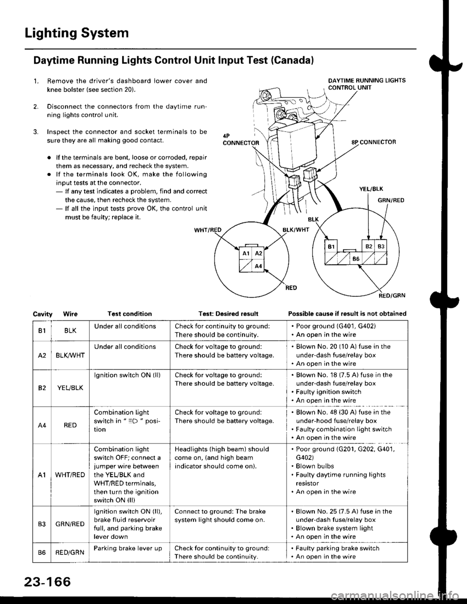
Lighting System
Daytime Running Lights Control Unit Input Test (Canadal
2.
3.
LRemove the driver's dashboard lower cover and
knee bolster (see section 20).
Disconnect the connectors from the daytime run-
ning lights control unit.
Inspect the connector and socket terminals to be
sure they are all making good contact.
lf the terminals are bent, loose or corroded. repair
them as necessary, and recheck the system.
lf the terminals look OK, make the following
input tests at the connector,- lf any test indicates a problem, find and correct
the cause, then recheck the system.- lf all the input tests prove OK, the control unit
must be faulty; replace it.
CavityWireTGst conditionTest: Desired resultPossible cause it result is not obtained
BLKU nderall conditionsCheck for continuity to g.ound:
There should be continuity.
. Poor ground (G401, G402). An open in the wire
A2BLK /VHT
Underall conditionsCheck for voltage to ground:
There should be battery voltage.
Blown No.20 (10 A) fuse in the
under-dash fuse/relay box
An open in the wire
etYEUBLK
lgnition switch ON (ll)Check for voitage to ground:
There should be battery voltage.
Blown No. 18 {7.5 A) fuse in the
under-dash luse/relay box
Faulty ignition switch
An open in the wire
A4RED
Combination light
switch in " =D " posi-
UOn
Check for voltage to ground:
There should be battery voltage.
Blown No. 48 (30 A) tuse in the
under-hood fuse/relay box
Faulty combination light switch
An open in the wire
A1WHT/RED
Combination light
switch OFF; connect ajumper wire between
the YEUBLK and
WHT/RED terminals,
then turn the ignition
switch ON (ll)
Headlights (high beam) should
come on, (and high beam
indicator should come on).
. Poor ground (G201, G202, G40'1,
G402). Blown bulbs. Faulty daytime running lights
resrstor. An open in the wire
GRN/RED
lgnition switch ON (ll),
brake fluid reservoir
full, and parking brake
lever down
Connect to ground: The brake
system light should come on.
Blown No.25 (7.5 A) fuse in the
under-dash f use/relay box
Blown brake system light
An open in the wire
REDiGRNParking brake lever LrpCheck for continuity to groundl
There should be continuity.
. Faulty parking brake switch. An open in the wire
23-166