under-dash HONDA CIVIC 1998 6.G Workshop Manual
[x] Cancel search | Manufacturer: HONDA, Model Year: 1998, Model line: CIVIC, Model: HONDA CIVIC 1998 6.GPages: 2189, PDF Size: 69.39 MB
Page 318 of 2189
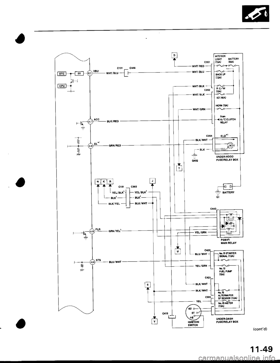
A/CO-UfAl
ELD''
;:l
T BLK
YEVGRI{
UNDER-HOODFUSE/RELAY BOX
UNDER-DASHFUg€/FELAY AOX
(cont'd)
BLtCWlfi -
*tT
sLrc /trt 1BLvwHr 1c501r.. -{
11-49
Page 378 of 2189
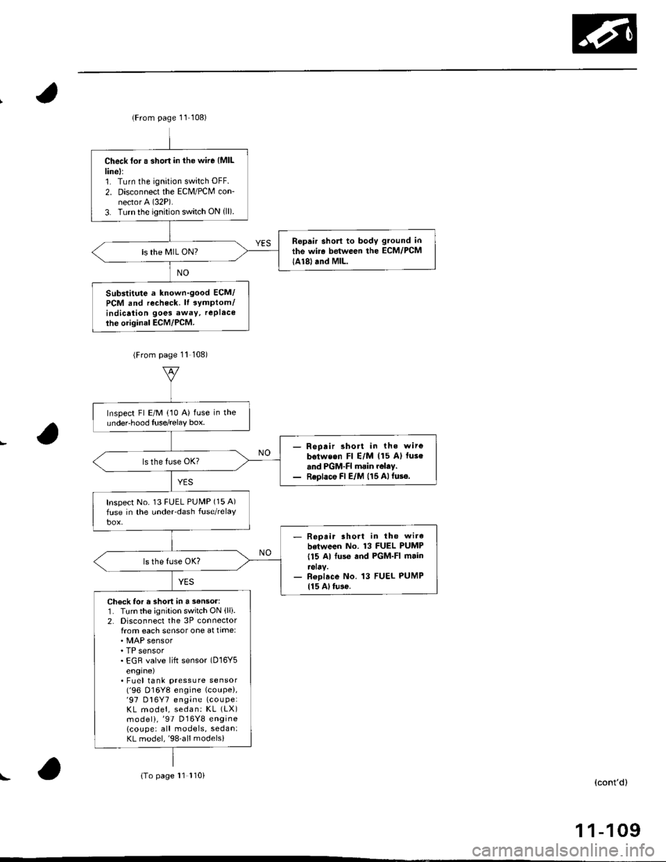
lFrom page 11 108)
Check for a short in the wire {MlLlinell1. Turn the ignition switch OFF.
2. Disconnect the Eclvl/PCM con-nector A (32P).
3. Turn the ignition switch ON {ll).
Ropair short to body gtound in
the wir. between the ECM/PCM
lA18) and MlL.ls the MIL ON?
Substitute a known-good ECM/
PCM and recheck. lt 3ymptom/indicaiion goes away, rePlace
ihe original ECM/PCM.
(From page 11 108)
Inspect Fl E/M (10 A) fuse in theundeFhood Iuse/relay box.
- Repair short in the wirg
b€tweon Fl E/M (15 A) luse
and PGM-FI main rolay.- Replace Fl E/M (15 Alfuse.
Inspect No. 13 FUEL PUMP (15 A)
fuse in the under-dash fuse/relaY
- Repait lhort in the wire
botween No. 13 FUEL PUMP
115 Al fuse and PGM-FI main
reray.- Roplace No. 13 FUEL PUMP115 Al tu3o.
Check for a short in a 3€nsor:1. Turn the ignition switch ON (lli.
2. Disconnecl the 3P connectorfrom each sensor one at time:
. TP sensor. EGR valve lift sensor (D16Y5
engrne). Fuel tank pressure sensor('96 D16Y8 engine (coupe),'97 D16Y7 engine (couPe:
KL model, sedan: KL (LX)
model),'97 D16Y8 engine
lcoupe: all models, sedan:KL model,'98-all models)
{To page 11 110)(cont'd)
1 1-109
!
Page 380 of 2189
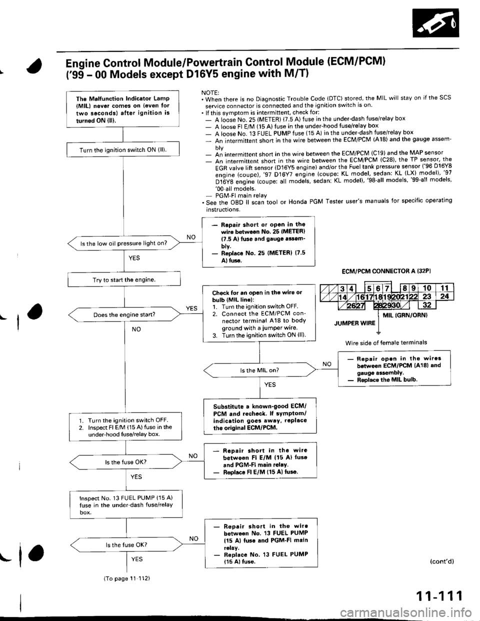
Engine Control Module/Powertrain Control Module (ECM/PCM)
('95 - 00 Models except Dl6Y5 engine with M/T)
NOTE:. When there is no Diagnostic Trouble Code lDTC) stored, the MIL will staY on if the SCS
seruice connector is connected and the ignition switch is on.. lf this symptom is intermittent, check for:- A loose No. 25 (METER) {7.5 A) fuse in the underdash fuse/relay box- A loose Fl E/M (15 Alluse in the undeFhood fuse/relay box- A loose No. 13 FUEL PUMPfuse (15 A) in the under-dash fuse/relay box- An intermittent shon in the wire between the ECM/PCM (A18) and the gauge assem'
- an intermittent short in the wire between the ECM/PCM (C19) and the MAP sensor- An intermittent short in the wire between the ECM/PCM {C28), the TP sensor, the
EGR valve lift sensor (D16Y5 engine) and/or the Fuel tank pressure sensor ('96 D16Y8
engine (coupe),'97 D16Y7 engine lcoupe: KL model, sodan: KL (LX) model)"g7
Dt6Y8 engine (coupe: all mod;ls, sedanl KL model),'98-all models,'99-al' models''00-all models.- PGM'FI main relay. See the oBD ll scan tool or Honda PGM Tester user's manuals for specific operating
instructrons,
ECM,/PCM CONNECTOR A I32PI
Wire side of {emale terminals
The Mrlfunction Indicator LamP{MlL) never comes on {even tor
two seconds) after ignition is
turned ON lll).
Turn the ignition switch ON lll).
- Repair shott or open in thowire bstwoon No. 25 IMETER)l?.5 A)tuse and gauga tsom_blv.- Reolace No. 25 (METERI (7.5
Alluse.
ls the low oil pressure light on?
Try to start the engine.
Check for an opon in the wire orbulb (MlL line):1. Turn the ignition switch OFF.2. Connect the ECM/PCM con'
nector terminal A18 to bodyground with a iumper wire.
3. Turn the ignition switch ON (ll)
Does the engine start?
- Repair open in tho wire3
betwoon ECM/PCM (A18) andgaugo .*tembly.- Rool.ce the MIL bulb.
Substitute a known-good ECM/
PCM and rochoc&. lf sYmptom/indication goes sw6y, repl.ce
tho original ECM/PCM.Turn the ignition switch OFF.Inspect Fl E/M (15 A)fuse in theunderhood Iuse/relay box.
Rop.ir short in the wirc
betwo€n Fl E/M (15 A) luso
and PGM-Fl mrin rGl.y.Reol.ce Fl E/M (15 A)tusa.
lnspect No. 13 FUEL PUMP {15 A}
luse in the under-dash fuse/relay
- Reoair short in the wiro
between No. 13 FUEL PUMP
115 Al luse sod PGM-FI mainrelay.- Reolace No. 13 FUEL PUMP115 A) tuse.
(To page 11 112)
(cont'd)
11-111
.f,
Page 472 of 2189

NOTE:. M/f: Clutch pedal must be depressed.. A,/T: Transmission in E or E position
ECM,/PCM CONNECTORS
I
This signals the ECM/PCM")
\
Starter Switch Signal ('99 - 00 Models except Dl6Y5 engine with M/T)
NOTE:. M/f: Clutch pedal must be depressed.. A,/T: Transmission in E or E position
ECM,/PCM CONNECTORS
I
This signals the ECM/PCM when the engine is cranking
Ch€ck for an open or short in the
wire {STS linel:Measure voltage between ECM/PC[/| connector terminals A24
and 820 with the ignition switch
in the start position (lll).
Inspect the No.31 STARTER SIG-NAL (7.5 Alluse in the under-dash
- Repair 3hort in tho wire be'
tween tho ECM/PCM lA24)and tho No. 31 STARTER SIG-NAL 17.5 Al fuse or the PGM-FImein relay.- ReDlaco the No. 31 STARTERSIGNAL 17.5 Al fuse.
Staner 3witch signal is OK.
Repair open in the wirc betwean
the ECM/PCM lA24) and the No.
31 STARTER SIGNAL {7.5 Alfuse.
W;re side of female terminals
Page 509 of 2189
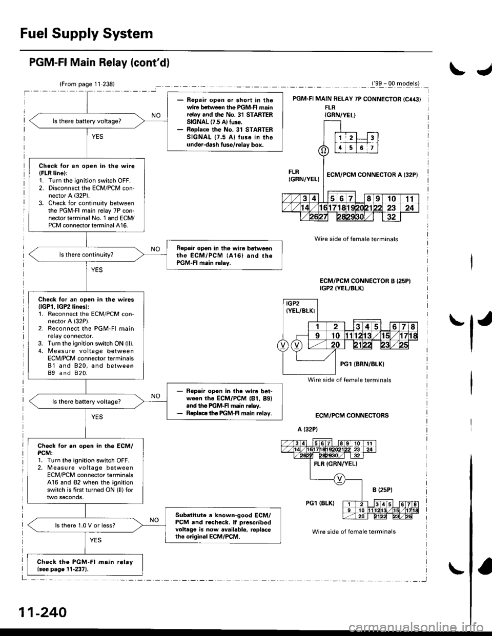
Fuel Supply System
- Repair op€n or short in thewir€ betlveen the PGM-FI mainrelay and the No. 31 STARTERSIGNAL 17.5 A) fuse.- RoDlace the No. 31 STARTERSIGNAL {7,5 Al tuse in theunder-dash luse/rolay box.
ls there battery voltage?
Check tor an open in the wire(FLR linel:1. Turn the ignition switch OFF.2. Disconnect the ECM/PCM con-nector A (32P).
3. Check for continuity betweenthe PGM-FI main relay 7P con-nector terminal No. 1 and ECM/PCM connector terminal A16.
Repair open in the wir6 botweenthe ECM/PCM (A161 and rhePGM-FI main relay.
Check for an open in the wires{lGPl, lGP2 line3):1. Reconnect the ECM/PCM con-nector A {32P).2. Reconnect the PGM-Fl mainrelay connector.3. Turn the ignition switch ON (ll).
4. Measure voltage betweenECN4/PCM connector terminals81 and 820, and betweenBg and 820.
- Repair open in the wire bet-ween th. ECM/PCM (81, Bg)snd the PGM-F main rolay.- Roplace th€ PGM-FI main relav.
Chock tor an open in th6 ECM/PCM:1. Turn the ignition switch OFF.2. Measure vo ltage betweenECM/PCM connector terminalsA16 and 82 when the ignitionswitch is first turned ON lll) for
Sub3titute . known-good ECM/PCM and rochock. lf prescribedvohege is now available, replacethe original ECM/PCM.
ls there 1.0 V or less?
Chock the PGM-Fl m.in r6lay{see p.ge 11-2371.
PGM-FI Main Relay (cont'd)
_._(9x . qq -gqerll _
PGM.FI MAIN FELAY 7P CONNECTOR {C4€}FLR
ECM/PCM CONNECTORS
A (32P1
Wire side ot female terminals
Wire side of fem6le terminals
ECM/PCM CONNECTOR B {25PIIGP2 {YEL/BLKI
IGRN/YEL}
IGP2(YEL/BLKI
Wire side of female terminals
11-240
IJ
'l'
Page 726 of 2189
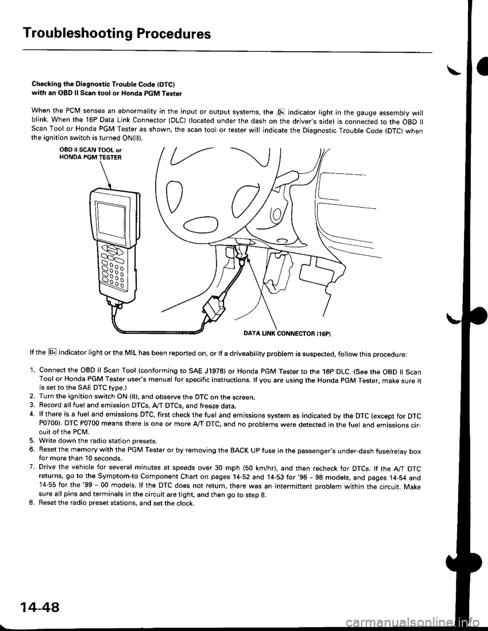
Troubleshootin g Procedures
Chccking the Diagnostic Trouble Code IDTC)with an OBD ll Scan tool or Honda PGM Tester
when the PCM senses an abnormality in the input or output systems, the pl indicator light in the gauge assembly willblink. When the 16P Data Link Connector (DLC) (located under the dash on the driver,s side) is connected to the OBD llScan Tool or Honda PGM Tester as shown, the scan tool or tester will indicate the Diagnostic Trouble Code (DTC) whenthe ignition switch is turned ON{ll).
lf the El indicator light or the MIL has been reported on, or lf a driveability problem is suspected, follow this procedure:
1. Connect the OBD ll Scan Tool (conforming to SAE J19781 or Honda PGM Tester to rhe 16p DLC. (See the OBD ll ScanTool or Honda PGM Tester user's manual for specific instructions. lf you are using the Honda PGM Tester, make sure itis set to the SAE DTC type.)
2. Turn the ignition switch ON (lll, and observe the DTC on the screen,3, Record all fuel and emission DTCS, A/T DTCS, and freeze data.4 lf there is a fuel and emissions DTC, first checkthe fuel and emissions system as indicated bythe DTC (except for DTCP0700). DTC P0700 means there is one or more A,/T DTC, and no problems were detected in the fuel and emissions cir-cuit of the PCM.
5. Write down the radio station oresets.
6. Reset the memory with the PGM Tester or by removing the BACK UP fuse in the passenger's under-dash fuse/relay boxfor more than 10 seconds.
7. Drive the vehicle for several minutes at speeds over 30 mph (50 km/hr), and then recheck for DTCS. lf the A"/T DTCreturns, go to the Symptom-to Component Chart on pages 14-52 and 14-53 for'96 - 98 models, and pages 14-54 and14-55 for the'99 - 00 models, lf the DTC does not return, there was an intermittent problem within the circuit. Makesure all pins and terminals in the circuit are tight, and then go to step g.
8. Reset the radio preset stations, and set the clock.
OBD ll SCAN TOOL orHONDA PGM TESTER
DAYA LINK CONNECTOR {16P}
14-44
Page 760 of 2189
Electrical Troubleshooting ('99 - 00 Models)
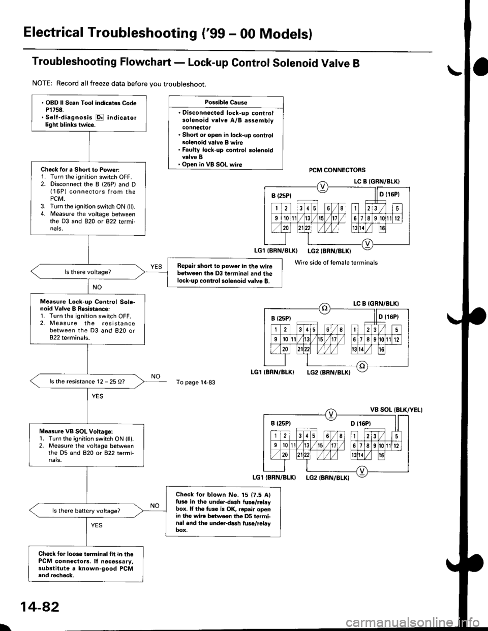
Troubleshooting Flowchart - Lock-up Control Solenoid Valve B
NOTE| Record allfreeze data before you troubleshoot.
Possibla Cause
. Oisconnected lock-uD controlsolenoid velve A/B assemblyconnector. Short or open in lock-up controlsolenoid valv€ B wire. Faulty lock-up control solenoidvalve B' Open in VB SOL wirercM CONNECTORS
To page 14-83
' OBD ll Scan Tool indic.tes CodeP1758.. Self-diagnosis E indicatorlight blinks twice.
Chack for a Short to Power:1. Turn the ignition switch OFF.2. Disconnect the I (25P) and D(16P) connectors from thePCM.3. lurn the ignition switch ON (ll).4. Measure the voltage betweenthe D3 and 820 ot 822 tetmi-nals,
Repair short to power in the wirebetween the D3 terminal and thelock-up contlol solenoid valve B.
Measure Lock-up Control Sole-noid Vdlve I R8i3tance:1. Turn the ignition switch OFF.2, Measure the resistancebetween the D3 and 820 or822 terminals.
ls the resistance 12 - 25 O?
Measure VB SOL Voltago:1. Turn the ignition switch ON lll).2. Measure the voltage betweenthe D5 and 820 or 822 termi-nals.
Check for blown No. 15 {7.5 Alfus€ in the under-dash luse/releybox. It the fuse is OK, repair openin the wir6 between th6 DS terminal and the under-dash fuse/rebyoox,
ls there battery voltage?
Chock for loose te.minal fit in thePCM connectors. It necessary,substitute a known-good PCMend recheck.
B t2sP) ll D t15P)
Wire side ol female terminals
I {2sPt ll D (16Pt
B (25P1 D t16Pt
\
14-82
Page 940 of 2189
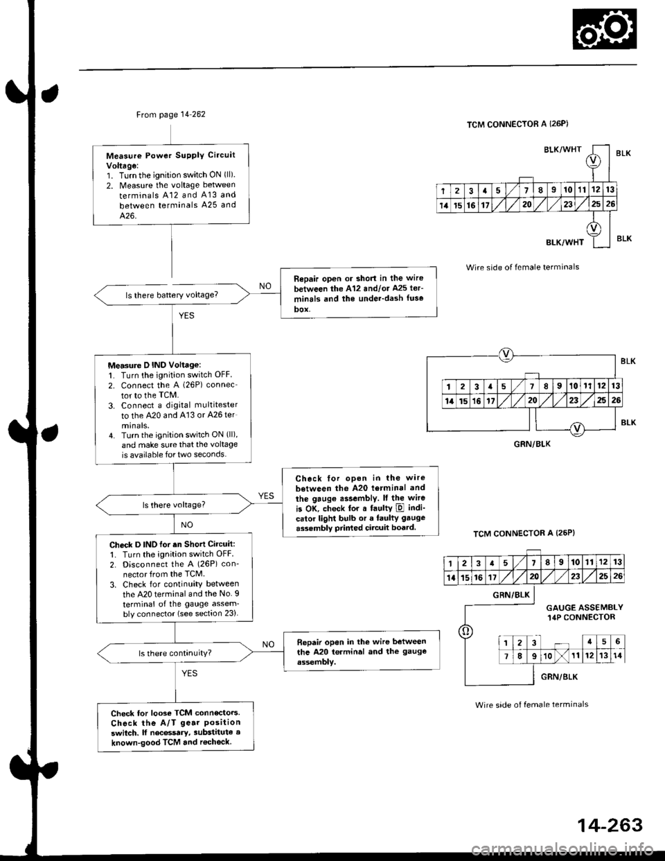
Ftom page 14 262
ls there battery voltage?
Measure Powet SUPPIY Ci.cuit
Voltage:1. Turnthe ignition switch ON (ll)
2. Measure the voltage between
terminals A12 and A13 and
between terminals A25 and
426.
Repair open or short in the wire
between the A'12 andlor Ms ler-
minrls and the under-dash fuse
DOX,
Measure D IND Voltage:1. Turn the ignition switch OFF
2. connect the A (26P) connec
tor to the TcM.
3. Connect a digkal multitester
to the A20 and A'13 or A26 ter
minals.4. Turn the ignition switch ON (ll),
and make sure that the voltage
is available for two seconds.
Check tor opon in the wire
between the A20 l6rminal and
the gaug€ assembly. It the wite
is OK, check tor a faultY ipl indi-
calor light bulb or a faulty gauge
assembly prir ed circuit boatd.
Check D INO for an Shott Circuit:1. Turn the ignition switch OFF
2. Disconnect the A (26P) con-
nector from the TCM.
3. Check for continuity between
the A20 terminal and the No. I
terminal of the gauge assem-bly connector (see section 23).
Bepair open in the wire between
the A20 terminal and the gauge
assembly.
Check tor looso TCM connecto.s.
Check the A/T ge.r Positionswitch. lf nec6ssary, substitute a
known-good TCM and r€check
BLK/WHTI
r
2a710111213
14t5161720232526
BLK/WHT
A
II
TCM CONNECTOR A I26P)
Wire side of female terminals
TCM CONNECTOR A (25P}
BLK
BLK
GRN/BLK
12a58910111213
1l15161720232526
o
GRN/BLK
GAUGE ASSEMBLY14P CONNECTOR
a5
78910111214
GRN/BLK
Wire side of female terminals
Page 948 of 2189
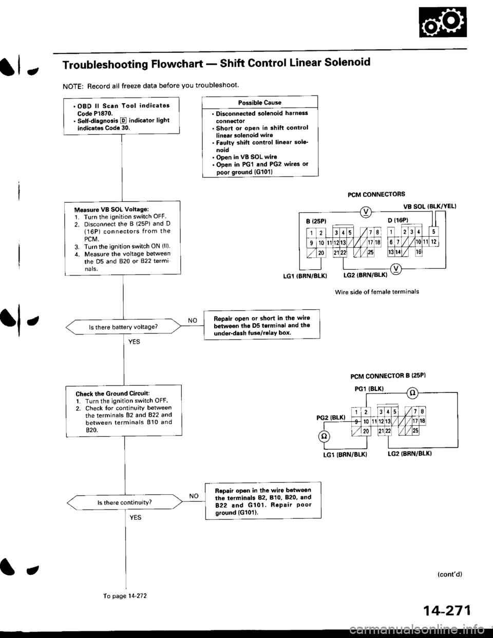
JTroubleshooting Flowchart - Shift Control Linear Solenoid
NOTE: Record all freeze data before you troubleshoot
Possiblc Cause
. Disconn€cted solenoid harnos3
connectol. Short or oDen in shilt controllinetr solonoid wiro. Faulty shift control linear sole_
noid. Op€n in VB SOL wite. ODen in PG'l and PG2 wires or
poor ground {G10'l)
f,
wire side ot female terminals
LG1 IBRN/BLKILG2IBRN/BLK)
{cont'd)
14-271
PCM CONNECTORS
B(25P) - Dll6P)
.OBD ll Scan Tool indicatos
Code P1870.. Solf-diagnosis E indic.lor light
indic.t€s Code 30.
M6a3ure VB SOL voltage:1. Turn the ignition switch OFF.
2. Disconnect the B 125P) and D(16P) connectors from the
PCM,3. Turn the ignition switch ON (ll).
4. Measure the voltage between
the D5 and 820 or 822 terminals.
Repair open or shod in the wire
between the D5 terminal and the
under-dash tuso/telay box.
Check the Ground Circuitl1. Turn the ignition switch OFF.2. Check lor continuity between
the terminafs 82 and 822 and
between terminals 810 and
820.
Repair open in the wi.e betwoen
the termin.ls 82, B10, B20, and
822 and G101. Repair Poolground (G101).
LG1 IBRN/BLKI
PCM CONNECTOR B PsPI
PG,I IBLK)
10 page 14-272
a
Page 1213 of 2189
Troubleshooting
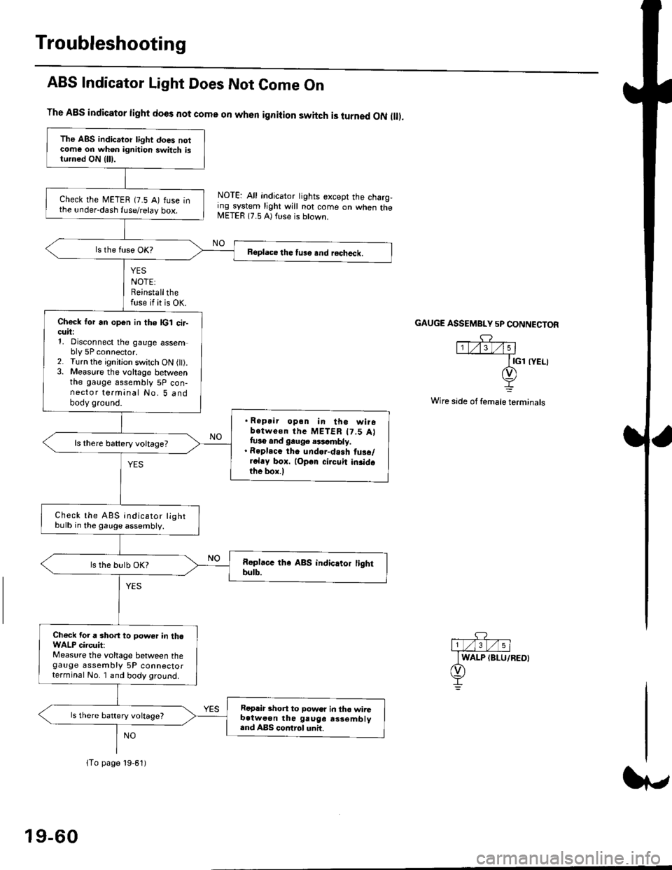
ABS Indicator Light Does Not Come On
YES
NOTE:Reinstallthefuse if it is OK.
The A8S indicator light does not come on when ignition switch is turned ON ll.
NOTE: All indicator tights except the charg,ing system light will not come on when theMETER 17.5 A) ft se is btown.
NO
GAUGE ASSEMBI"Y 5P CONNECTOR
Wire side of female terminals
Tho ABS indicator light does notcome on wh€n ignition switch istu.ned ON {lll.
check the METEB (7.5 A) fuse inthe under-dash fuse/relay box.
Beplace the tu3e and recheck.
Check for an open in th6 lcl cir-cuii:1, Disconnect the gauge assembly 5P connector.2. Turn the ignitjon switch ON l).3. Measure the voltage betweenthe gauge assembly 5P con-nector terminal No. 5 andbody ground.
. Ropair opan in tho wirobotwe€n thc METER t7.5 Attuso and gauge .$cmbly.. Roplacc th. und.r-dash tus./r.l.y box. lop.r cirouit in3idothe box.l
ls there baftery voltage?
Check the ABS indicator lightbulb in the gauge assembly.
ls the bulb OK?
Ch€ck tor a short to power in theWALP circuit:Measure the voltage between thegauge assembly 5P connectorterminal No. I and body ground.
Replir short to power in tho wiiGb.tweon the gruge rs3embly.nd ABS control unh.
ls there battery voltage?
lTo page 19-61)
19-60