CABLE HONDA CIVIC 1999 6.G Owner's Manual
[x] Cancel search | Manufacturer: HONDA, Model Year: 1999, Model line: CIVIC, Model: HONDA CIVIC 1999 6.GPages: 2189, PDF Size: 69.39 MB
Page 478 of 2189
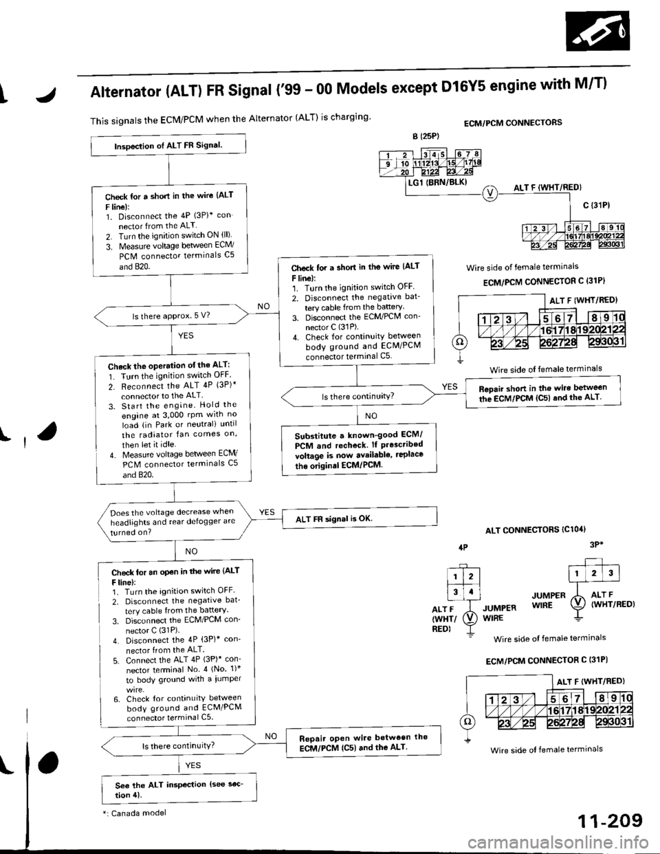
tAlternator (ALT) FR Signal ('99 - 00 Models except Dl6Y5 engine with M/T)
This signals the ECM/PCM when the Alternator {ALT) is chargingECM/PCM CONNECTORS
Wire side of female terminals
ECM/PCM CONNECTOR C (31P}
lt
lP
ALT CONNECTORS IClO4I
JUMPER
JUMpER WlnE
WIRE
Wire side of female termlnals
ECM/PCM CONNECTOR C (31PI
3P*NO
Check lor an op€n in the wire (ALT
F line,:1. Turn the agnition switch OFF
2. Disconnect the negative bat-
tery cable {rom the battery.
3. Disconnect the ECM/PCM con'
nector C (31P).
4. Disconnect the 4P (3P)* con'
nector from the ALT.
5. Connect the ALT 4P (3P)* con-
nector terminal No 4 (No. 1)*
to bodY ground with a iumper
6. Check lor continuity between
body ground and ECM/PCM
connector terminal C5
--?--1l2l|�#i3l.l
otriJrwxrr (V)
neor Y
lnsoeclion oI ALT FB Signal.
Check {or a short in the wire {ALT
F line):1. Disconnect the 4P (3P)+ con
nector from the ALT
2. Turn the ignition switch ON (ll)
3. Measurc voltage between EcM/
PCM connector terminals C5
and 820.Check tor a short in the wirc (ALt
F line):1. Turn the ignition switch OFF
2. Disconnect the negative bat_
tery cable from the baRery'
3. Disconnect the ECM/PCM con'
nector C (31P).
4. Check for continuity between
body ground and ECM/PCM
connector terminal C5
ls there aPProx. 5 V?
Check the operation otthe ALT:
1. Turn the ignition switch OFF.
2- Reconnect the ALT 4P (3P)*
connector to the ALT
3. Start the engine. Hold the
engine at 3,000 rpm wrth no
load {in Park or neutrali until
the radiator fan comes on,
then let it idle.
4- Measure voltage between ECM/
PCM connector terminals C5
and 820.
Repair short in the wire between
the EcM/PCM {C5l and the ALT.
Substitute a known-good ECM/
PCM and rechock. lf P.esc.ibedvoltage is now availabl€, ieplace
tho original ECM/PCM
Does the voltage decrease when
headlights and rear delogger are
turned on?
ALT FF signal is OK.
Repair oPen wire betwoen t|lo
ECM,/PCM {C5) and the ALT.
ALT F (WHT/RED)
Wire side of temale terminals
*: Canada model
Wire side of female termrnals
Page 498 of 2189
t
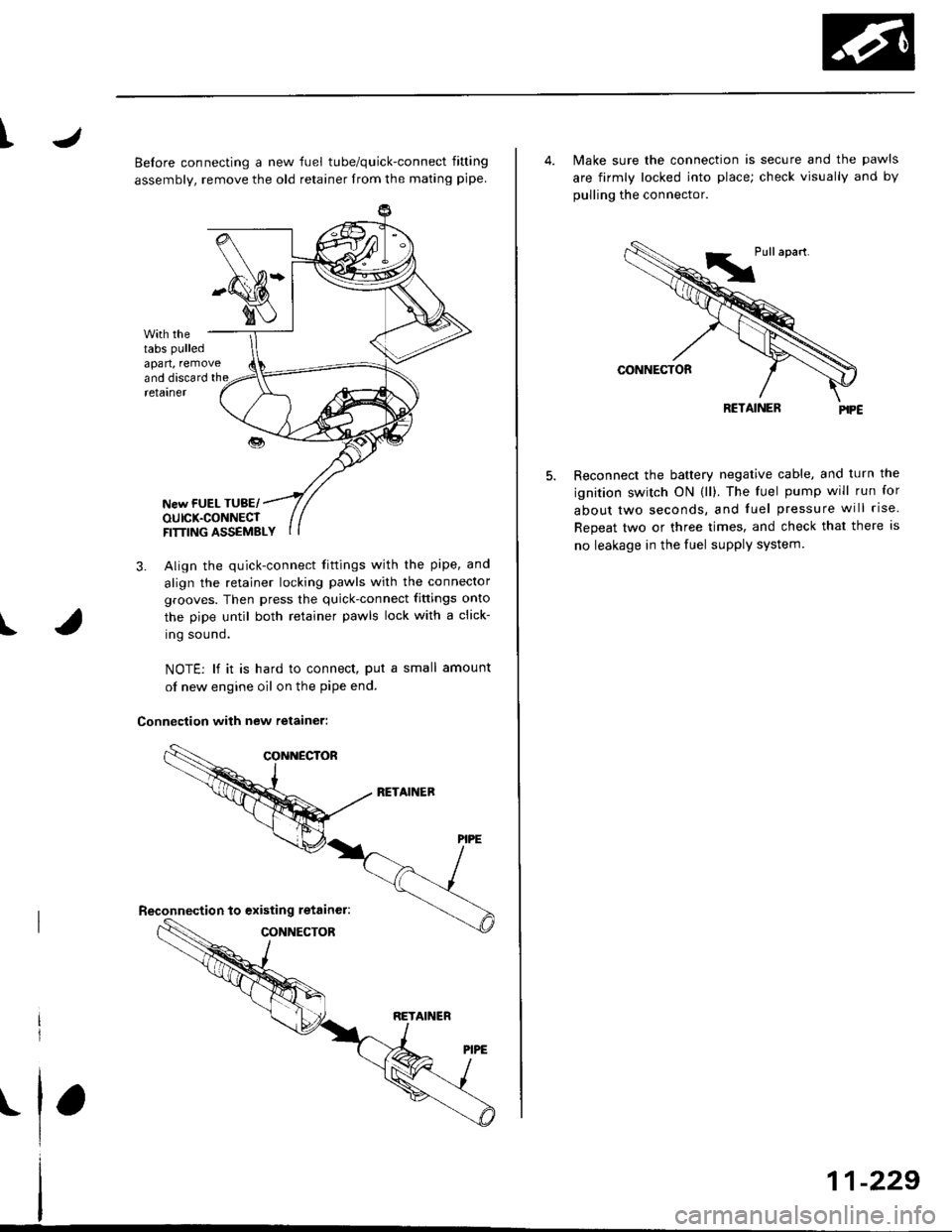
Belore connecting a new fuel tube/quick-connect fining
assembly, remove the old retainer from the mating pipe
with thetabs pulled
apan, removeand discard the
I
retarner
New FUEL TUBE/OUICK.CONNECTFITTING ASSEMELY
3. Align the quick-connect fiftings with the pipe, and
align the retainer locking pawls with the connector
grooves. Then press the quick-connect fittings onto
the pipe until both retainer pawls lock with a click-
ing sound.
NOTE: lf it is hard to connect, put a small amount
of new engine oil on the pipe end.
Connection with new retainer:
4. Make sure the connection is secure and the pawls
are firmly locked into place; check visually and by
pulling the connector.
RCTAINER
Reconnect the battery negative cable, and turn the
ignition switch ON (ll). The fuel pump will run for
about two seconds, and fuel pressure will rise.
Repeat two or three times, and check that there is
no leakage in the fuel supplv system
11-229
Page 499 of 2189
Fuel Supply System
System Description
The fuel supply system consists of a fuel tank, in-tank
high pressure fuel pump, PGM-FI main relay, fuelfilter,
fuel pressure regulator, fuel injectors. and fuel delivery
and return lines. This system delivers pressure-regu-
lated fuel to the fuel injectors and cuts the fuel delivery
when the engine is not running.
Fuel Pressure l'96 Modelsl
Relieving
Before disconnecting fuel pipes or hoses, release pres-
sure from the system by loosening the 6 mm service
bolt on top of the fuel filter.
. Do not smoke whil6 working on the fuel system.
Kgsp opon flames or sparks away from youl work
area.
. Be sure to relieve fuel pressure while the ignition
switch is off.
1. Write down the frequencies for the radio's preset
buttons.
2. Disconnect the battery negative cable from the bat-
tery negative terminal.
3. Remove the fuelfill cap,
4. Use a box end wrench on the 6 mm service bolt at
the fuel filter while holding the special banjo bolt
with another wrench,
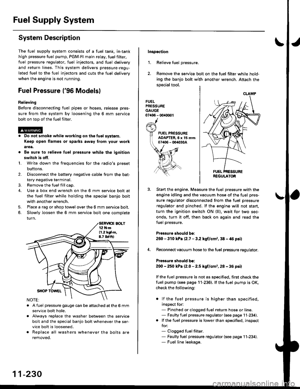
5. Place a rag or shop towel over the 6 mm service bolt.
6, Slowly loosen the 6 mm service bolt one complete
rurn.
. A fuel pressure gauge can be attached at the 6 mm
service bolt hole.
. Always reDlace the washer between the service
bolt and the special banjo bolt whenever the ser-
vice bolt is loosened.
. Replace all washers whenever the bolts are
removeo.
11-230
Inspoction
1. Relieve fuel pressure.
2. Remove the service bolt on the fuel filter while hold-
ing the banjo bolt with another wrench. Attach the
special tool.
FUELPRESSUREGAUGE07406 - 00ir0(x)1
Start the engine. Measure the fuel pressure with the
engine idling and the vacuum hose of the fuel pres-
sure regulator disconnected from the fuel pressure
regulator and pinched. lf the engine will not start,
turn the ignition switch ON (ll), wait for two sec-
onds, turn it off, then back on again and read the
fuel pressure.
Pr€3sure should bo:
260 - 310 kPa (2.7 - 3.2 kgt/cmr, 38 - 46 psi)
Reconnect vacuum hose to the fuel pressure regulator,
Pressure should bo:
200 - 25O kPa l2.O - 2.5 kgf/cm'�, 28 - 36 psil
lf the fuel pressure is not as specified, first check the
fuel pump {see page 11-2361. lf the fuel pump is OK,
check the following:
. lf the fuel pressure is higher than specified,
inspect for;- Pinched or clogged fuel return hose or line.- Faulty fuel pressure regulator (see page 11-234).. lf the fuel pressure is lower than specified, inspect
for:- Clogged fuelfilter.- Faulty fuel pressure regulator {see page 11-234).- Fuel line leakage.
REGULATOB
Page 500 of 2189
tJFuel Pressure {'97 and later Models)
ReliGving
Before disconnecting tuel pipes or hoses, release pres-
sure from the system by loosening the 12 mm banjo
bolt on top of the fuel filter.
@o Do not smoke whilo working on the fuel sy3lom.
Ksgp op€n flames or sparks away tlom Your work
arga.
. Be sure to relieve fuel pressule while the ignition
swhch is off.
1. Write down the frequencies for the radio's preset
buttons,
2. Disconnect the battery negative cable from the bat-
tery negative terminal.
3. Remove the fuel fill cap.
Use a box end wrench on the 12 mm banjo bolt at
the fuel filter while holding the fuel filter with anoth-
er wrench.
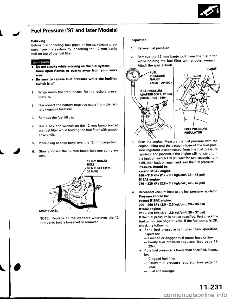
Place a rag or shop towel over the 12 mm banio bolt.
Slowly loosen the 12 mm banjo bolt one complete
turn.
4.
I
12 mm BAtt OBOLT33 N.m (3.i1 kgf m,25 tbf.f0
NOTE: Replace all the washers whenever the 12
mm banio bolt is loosened or removed.
Inspaqtion
1. Relieve fuel pressure.
2. Remove the 12 mm banjo bolt from the fuel filter
while holding the fuel Jilter with another wrench
Attach the special tools.
3. Start the enginethe fuel Pressure with the
engine idling and the vacuum hose of the fuel pres-
sure regulator disconnected from the fuel pressure
regulator and pinched lfthe engine will not start, turn
the ignition switch ON {ll), wait for two seconds, turn
it off, then back on again and read the fuel pressure'
Pr$3uro ehould be:
excepi 816A2 sngine:
260 - 310 kPa {2'7 - 3.2 kgf/cm" 38 - {6 Fi}
B16A2 engine:
27O -32O kPa P.8 - 3'3 kgf/cm'�, '10 - 47 psi)
4. Reconnect vacuum hoso to the fuel pressure regulator'
Pre33ure 3hould be:
except B16A2 engin€:
2OO - 250 kPa {2.0 - 2'5 kgf/cm'�, 28 - 36 psi)
B16A2 engino:
210 - 260 kPa 121 - 2.6 ksf/cm'�, 30 - 37 psi)
lf the fuel pressure is not as specified, first check the
fuel pump (see page 11-236) lfthetuel pumpisoK,
check tho following:
. lf the fuel pressure is higher than specified,
inspect for:- Pinched or clogged fuel return hose or line.
- Faulty fuel pressure regulator (see page 11-
2341.
. lf the fuel pressure is lower than specified, inspect
for:- Clogged fuel filter.
- Faulty fuel pressure regulator (see page l1-
2341.- Fuel line leakage.
FUEL PRESSUREADAPTER BOLT, 12 mm
tguxt8-PD6-0101
CLAMP
REGULATOR
11-231
Page 513 of 2189
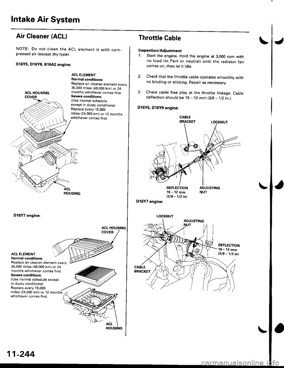
lntake Air System
Air Cleaner (ACLI
NOTE: Do not clean the ACL element it with com-pressed air {except dry type).
D16Y5, D16Y8, 816A2 engine:
ACL ELEMENTNormal conditions:Replace air cleaner element every30,000 miles (48,000 km) or 24months whichever comes first.S€voae conditions:(Use normal scheduleexcept in dusty conditions)Replace every 15,OOOmiles (24,000 km)or 12 monthswhichever comes first.
D16Y7 engine:
ACL ELEMENTNormal conditions:Replace air cleaner element every30,000 miles (48,000 km) or 24months whichever comes first,Seve.s conditions:(Use normal schedule exceptin dusty conditions)Replace every l5,000
whichever comes first.
11-244
Throttle Cable
Inspection/Adiustment
1. Start the engine. Hold the engine at 3,000 rpm withno load (in Park or neutral) until the radiator fancomes on, then let it idle.
2. Check that the throftle cable operates smoothly withno binding or sticking. Repair as necessary.
3. Check cable free play at the throttle linkage. Cabledeflection shoutd be 10- l2 mm (3/B - 112 in.l.
D16Y5, D16Y8 engine:
CABLEBRACKETLOCKNUT
DEFLECTION10-12mm
BIA- 112 inl
D16Y7 engine:
LOCKNUT
DEFLECTION10- 12 mml3lA - lninl
Page 514 of 2189
\J
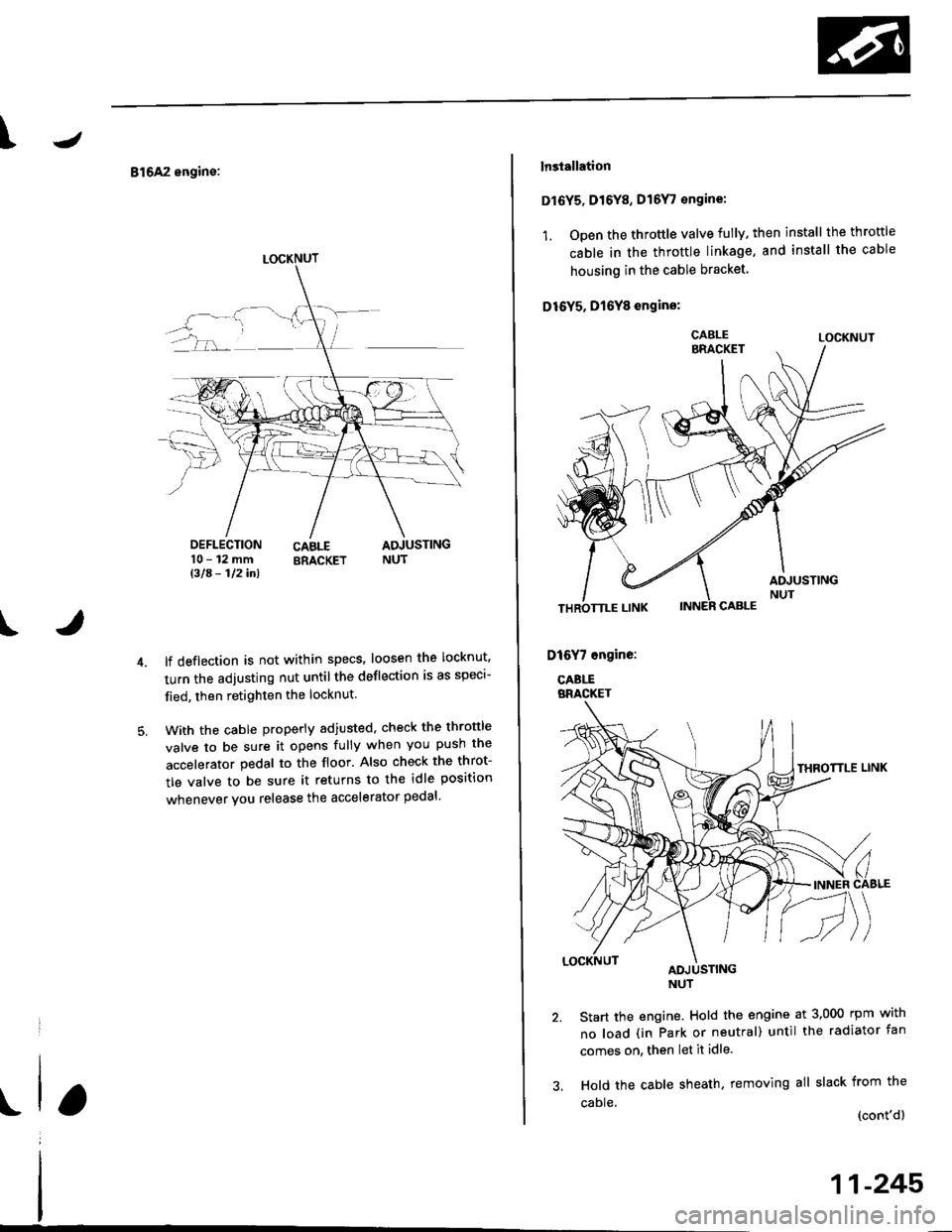
816A2 engine:
DEFLECTION10-12mmBla- 112inl
CABLE ADJUSTINGBRACKET NUT
t
lf deflection is not within specs' loosen the locknut'
turn the adjusting nut untilthe deflection is as speci-
fied, then retighten the locknut.
With the cable properly adiusted, check the thronle
valve to be sure it opens fully when you push the
accelerator pedal to the floor. Also check the throt-
tle valve to be sure it returns to the idle position
whenever you release the accelerator pedal'
LOCKNUT
lnstallation
Dl6Y5, Dr6Y8, D16Y, €ngine:
1. Open the throttle valve fully, then install the throttle
cable in the throttle linkage, and install the cable
housing in the cable bracket.
D16Y5, D16Y8 engins:
LOCKNUT
Start the engine. Hold the engine at 3,000 rpm with
no load (in Park or neutral) until the radiator fan
comes on, then let it idle.
Hold the cable sheath. removing all slack from the
caDle (cont'dl
11-245
Page 515 of 2189
Intake Air System
Throttle Cable (cont'dl
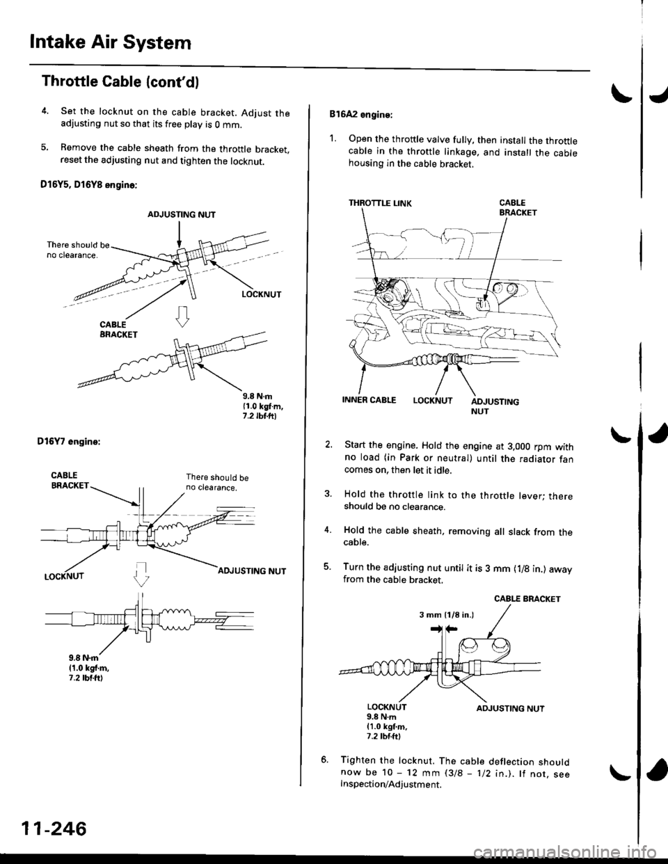
4. Set the locknut on the cable bracket. Adjust theadjusting nut so that its free play is O mm.
5. Bemove the cable sheath from the throttle bracket,reset the adjusting nut and tighten the locknut.
O16Y5, D16Y8 engino:
ADJUSTING NUT
9.8 N.m{1.0 kgl.m,1.2 tbt.ttl
DtGYT 6ngine:
11-246
816A2 engine:
1. Open the throttle valve fully, then install the throttlecable in the throttle linkage. and install the cablehousing in the cable bracket,
THROTTLE LINK
LOCKNUTADJUSTINGNUT
Start the engine. Hold the engine at 3.000 rpm withno load (in Park or neutral) until the radiator fancomes on, then let it idle.
Hold the throttle link to the throttle lever; thereshould be no clearance.
Hold the cable sheath, removing all slack from thecable.
Turn the adjusting nut untit it is 3 mm {1/8 in.) awayfrom the cable bracket,
LOCKNUT9.8 N.m(1.0 kgt m,7.2 tM.ttl
ADJUSTING NUT
Tighten the locknut. The cable deflection shouldnow be 10 - 12 mm l3/B - 1/2 in.). lf nor. seeInspection/Adjustment.
3 mm 11/8 in.)
Page 516 of 2189
IThrottle BodY
Description
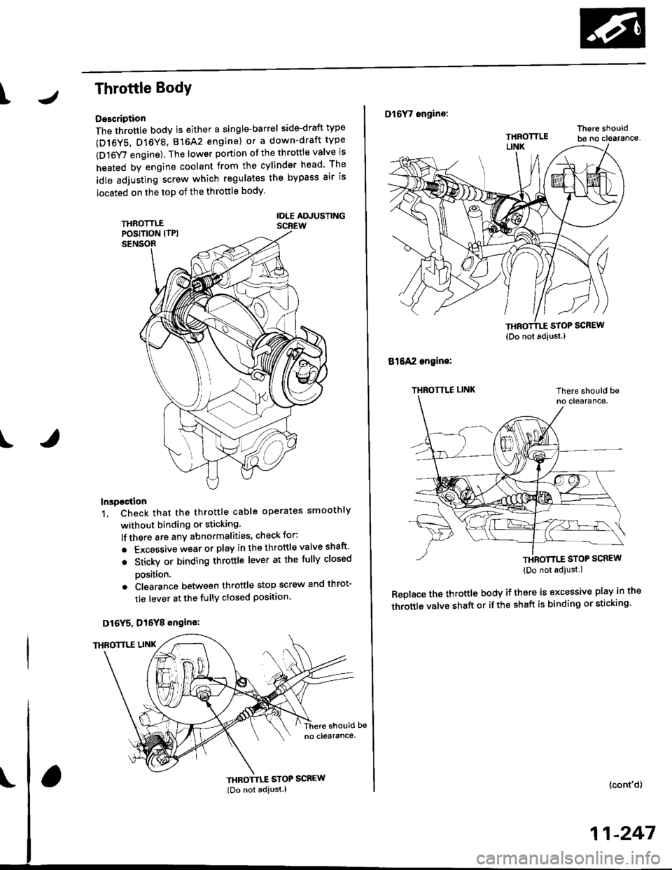
The throttle bodY is either a single-barrel side-draft type
(D16Y5, D16Y8, 816A2 engine) or a down-draft type
(D16Y/ engine). The lower portion ot the throttle valve is
heated by engine coolant from the cylinder head' The
idle adjusting screw which regulates the bypass air is
located on the top of the throttle body
THROTTLEPOS|T|ON lTPlSENSOR
IDLE AD.'USTINGSCREW
t
In3pection
1. Check that the throttle cable operates smoothly
without binding or sticking.
lf there are any abnormalities, check for:
. Excessive wear or play in the throttle valve shaft'
. StickY or binding throttle lever at the fully closed
Position.. Clearance between throttle stop screw and throt-
tle lever at the fully closed position'
D16Y5, Dl6Y8 engine:
THROTTLE STOP SCREW
{Do not adjust.)
Dl6Y7 ongine:
816A2 engins:
THROTTLE LINK
STOP SCREW
THROTTTE STOP SCREW(Do not adjust.)
Replace the throftle body if thsre is excessive play in the
throttle valve shaft or iJ the shaft is binding or sticking'
(cont'd)
11-247
{Do not adjust.)
Page 517 of 2189
Intake Air System
J
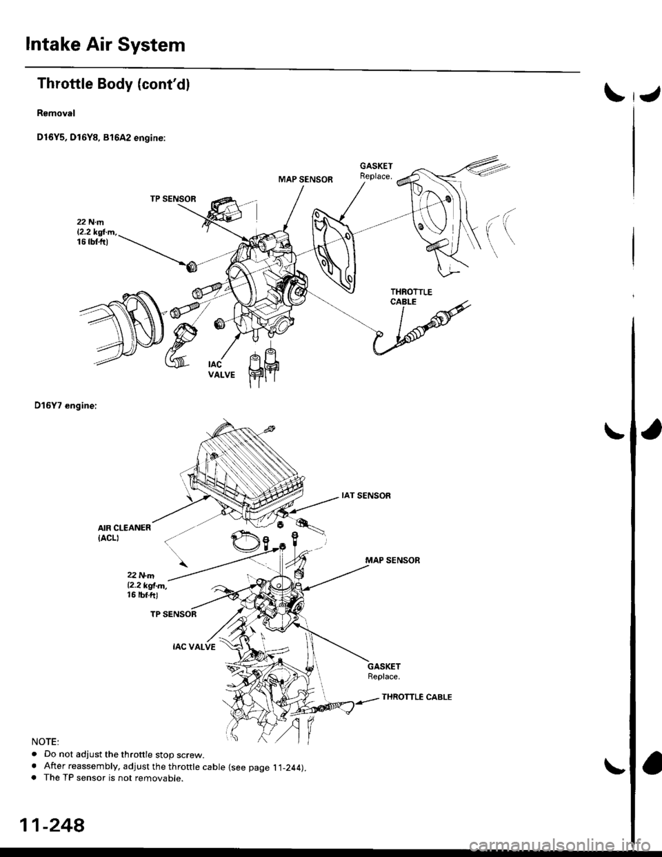
Throttle Body (cont'dl
Removal
D16Y5, Dl6Y8, 81642 engine:
D15Y7 engine:
AIR CLEANER
{ACLI
22 N.m12.2 kgl.m,16 rbf.ftl
NOTE:
. Do not adjust the throttle stop screw.. After reassembly, adjust the throttle cable {see page l l-244).. The TP sensor is not removable.
IAT SENSOR
MAP SENSOR
GASKETReplace.
11-248
THROTTLE CABLE
Page 585 of 2189
Transmission Assembly
I
Removal
@. Make sure iacks and safety stands are placed prop€dy,
and hoist brackets are atlach€d to correct position on
the enginc.
. Apply parking brake and block rear whosls so car will
nol roll olf stands and lall on you while working under
it.
CAUTION: Use fender covers to svoid damaging painted
surfaces.
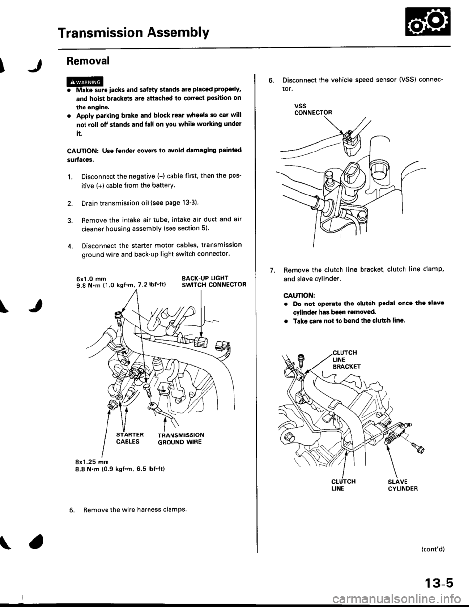
1. Disconnect the negative {-) cable first, then the pos-
itive (+) cable from the battery'
Drain transmission oil {see page 13-3).
Remove the intake air tube. intake air duct and air
cleaner housing assembly (see section 5).
Disconnect the starter motor cables, transmission
ground wire and back-up light switch connector.
6x1.0 mm BACK-UP LIGHT
9.8 N.m (1.0 ksf.m, 7.2 lbI.ft) swlTcH CoNNECTOR
8x 1 .25 mm8.8 N.m {0.9 kgt.m,6.5 lbf.ftl
\
ARTER
5. Remove the wire harness clamps.
vssCONNECTOR
6. Disconnect the vehicle speed sensor (VSS) connec-
ror.
Remove the clutch line bracket, clutch line clamp,
and slave cvlinder.
CAUTION:
. Do not opsr.te tho clutdh pedal once the 3lavc
cylindor has b6on romoved.
. Tske care not to bend tha clutch lin6.
7.
(cont'd)
13-5