ect HONDA CIVIC 1999 6.G Workshop Manual
[x] Cancel search | Manufacturer: HONDA, Model Year: 1999, Model line: CIVIC, Model: HONDA CIVIC 1999 6.GPages: 2189, PDF Size: 69.39 MB
Page 1018 of 2189
Transmission
Reassembly (cont'd)
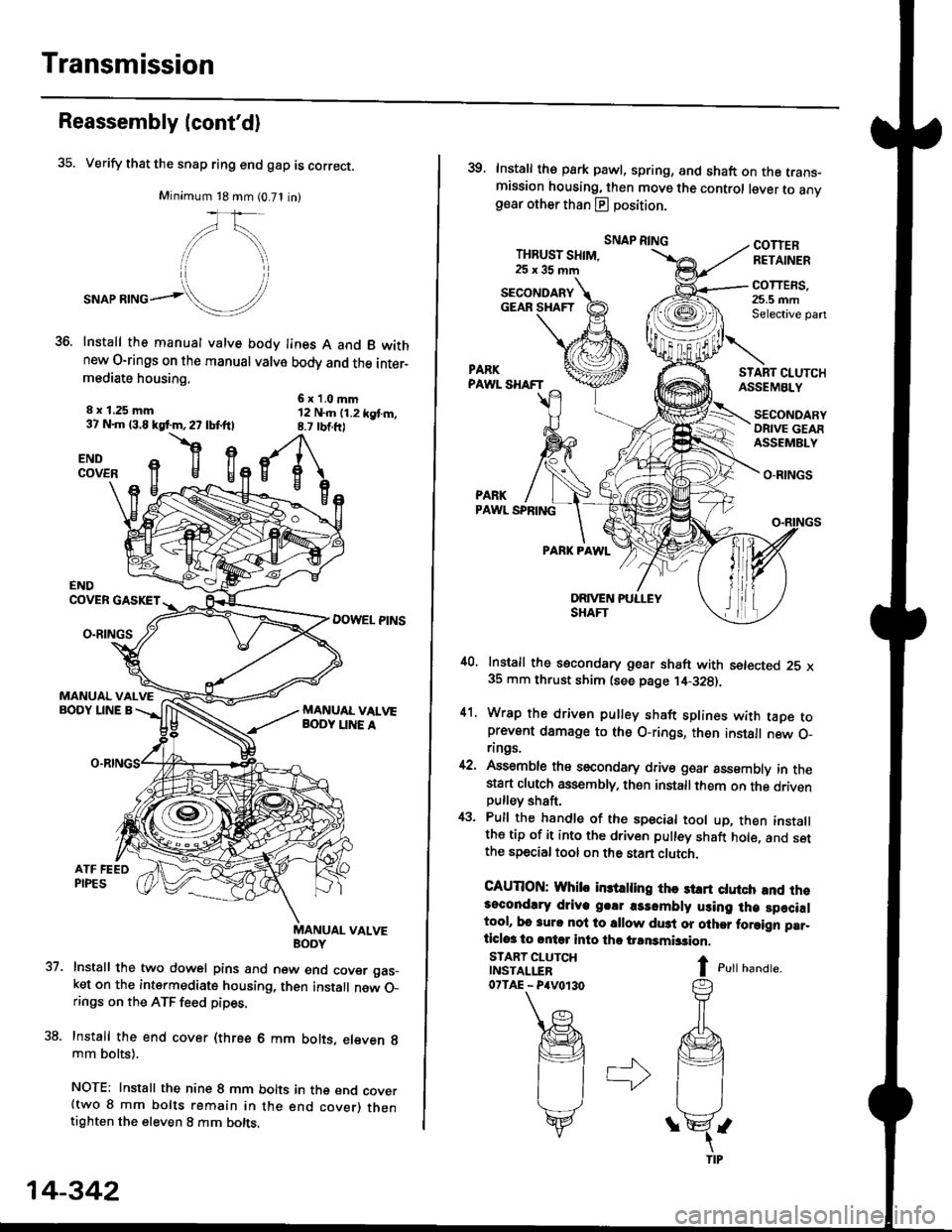
35. Verify that the snap ring end gap is correct.
Minimum 18 mm (0.71 in)
,/\,
."or**ol!/'
Install the manual valve body lines A and B wkhnew O-rings on the manual valve body and the inter-mediate housing.
6x1.0mm12 N..n (1.2 kgt m,8.7 rbtft)
8 x 1.25 mm37 N.m 13.8 kgf.m,27 lbf.ftl
flgENDCOVER
37.
ENDCOVER GASKET
DOWEL PINSO-RINGS
MANUAL VALVEBODY LINE A
uaNYuAL VALVE
Install the two dowel pins and new end cover gas_ket on the intermediate housing, then install new O_rings on the ATF feed pipes.
Install the end cover (three 6 mm bolts, eleven g
mm bolts).
NOTE: Install the nine 8 mm bolts in the end cover(two 8 mm bolts remain in the end cover) thentighten the eleven 8 mm bolts.
14-342
39. Install the park pawl, spring, and shaft on the trans-mission housing, then move the control lever to anvgear other than E position.
THBUST SHIM,25x35mm
SNAP RINGCOTTERRETAINER
COTTERS,25.5 mmSelective pan
START CI.UTCHASSEMBLY
O.RINGS
PARKPAWL SPRING
PARK PAWL
,10, Install the secondary gear shaft with setected 25 x35 mm thrust shim (see page ,14-328).
41. Wrap the driven pulley shaft splines with taDe toprevent damage to the O-rings, then install new O_rings.
42, Assemble ths secondary drive goar assembly in thestart clutch assembly, then installthem on the drivenpulley shaft,
43. Pull the handle of the special tool up, then installthe tip of it into the driven pulley shaft hole, and setthe special tool on the stan clutch.
CAUTION: Whib in3trling thc st rt ctutch and rh.3ocondlry driye g.!r a3sombly using lh€ specialtool, bo 3urc nol to sllow du3t or olher foraign par_ticlos to ontq into tho iransmbsion.
I c,rr r,unar".
SECONDARYGEAR SHAFT
START CLUTCHINSTALLER07TAE - P4V0r30
SECONDARYORIVE GEAFASSEMBLY
Page 1019 of 2189
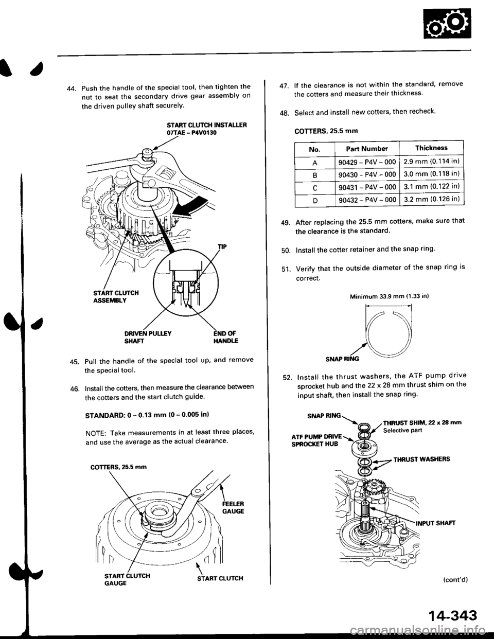
44. Push the handle of the special tool, then tighten the
nut to seal the secondary drive gear assembly on
the driven pulleY shaft securelY.
STAAT CLUTCH Ii'ISTALIIR07TAE - PaV0130
OF
46.
SHAFTHA'{DI,-E
Pull the handle of the special tool up, and remove
the special tool.
lnstallthe cotters, then measure the clearance Delween
the cotters and the start clutch guide
STANDARD: 0 - 0.13 mm (0 - 0.005 inl
NOTE: Take measurements in at least three places,
and use the average as the actual clearance
GAUGE
lil(il
COTTERS, 25.5 mm
START 1
GAUGCSTART CLUTCH
14-343
47.
48.
lf the clearance is not within the standard, remove
the cotters and measure their thickness
Select and install new cotters, then recheck.
COTTERS, 25.5 mm
After replacing the 25.5 mm cotters, make sure that
the clearance is the standard
lnstall the cotter retainer and the snap rlng
Verify that the outside diameter of the snap ring is
correct.
Minimum 33.9 mm (1.33 in)
SNAP RII{G
lnstall the thrust washers. the ATF pump drrve
sprocket hub and the 22 x 28 mm thrust shim on the
inDUt shaft, then install the snap ring.
49.
50.
52.
THRUST WASXERS
INPUT SHAFT
(cont'd)
No.Part NumberThickness
90429-P4V-0002.9mm(0.114 in)
B90430-P4V-0003.0mm(0.118 in)
c90431 -P4V-0003.1 mm (0.122 ln)
D90432-P4V-0003.2 mm (0.126 in)
SNAPRING\
ATF PUMP DRIVESPROCKET HUB
THFUST SHIM, 22 x 2a mm
Selective pan
Page 1020 of 2189
Transmission
Reassembly (cont'd)
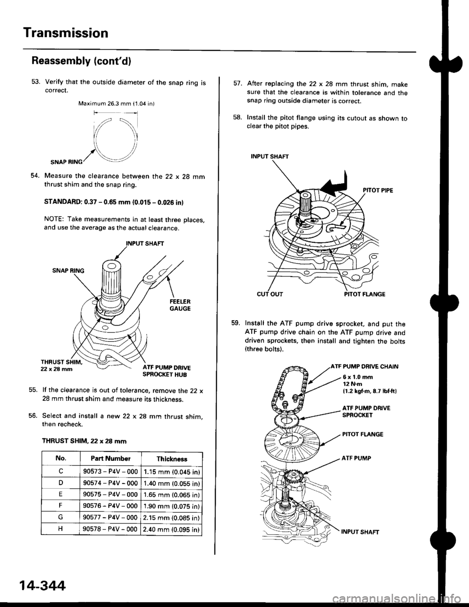
53. Verify that the outside diameter of the snap ring iscorrect.
Maximum 26.3 mm (1.04 in)
54.
SNAP RING
Measure the clearance between the 22 x 28 mmthrust shim and the snap ring.
STANDARD: 0.37 - 0.65 mm (0.015 - 0.026 inl
NOTE: Take measurements in at least three places,
and use the average as the actual clearance.
lf the clearance is out of tolerance, remove the 22 x
28 mm thrust shim and measure its thickness.
Select and install a new 22 x 28 mm thrust shim,then recheck.
THRUST SHIM, 22 x 28 mm
55.
co.
No.Part Numb€rThicknsss
c90573-P4V-0001.15 mm (0.0,{5 in)
D90574-P4V-0001.40 mm {0.055 in)
E90575-P4V-0001.65 mm (0.065 in)
F90576-P4V-0001.90 mm (0.075 in)
90577-P4V-0002.15 mm (0.085 in)
90578-P4V-0002.40 mm (0.095 in)
14-344
INPUT SXAFT
After replacing the 22 x 28 mm thrust shim. makesure that the clearance is within tolerance and thesnap ring outside diameter is correcr.
Install the pitot flange using its cutout as shown toclear the pitot pipes.
Install the ATF pump drive sprocket. and put theATF pump drive chain on the ATF pump drive anddriven sprockets, then install 8nd tighten the bolts(three bolts).
TF PUMP DRIVE CHAIN
58.
59.
6x1.0mm12 N.m
11.2 kg{.m,8.7 lbf.ftl
ATF PUMP ORIVESPROCKET
PITOT FLANGE
ATF PUMP
Page 1021 of 2189
l.
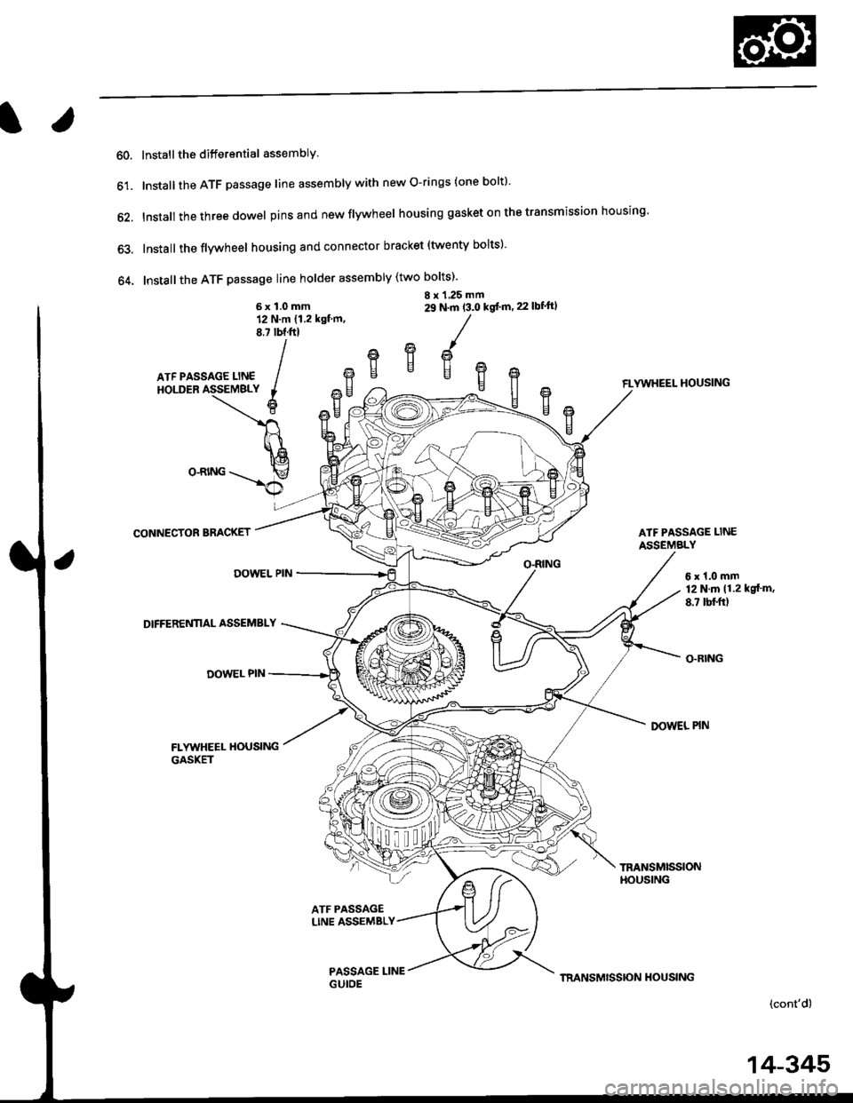
60. Install the ditferential assembly
61. Installthe ATF passage line assembly with new O-rings (one boltl'
62. Install thethreedowel pinsand new flywheel housing gasket on the transmission housing'
63. Install the flywheel housing and connector bracket (twenty bolts)'
64. Installthe ATF passage line holder assembly (two bolts)'
8 x 1.25 mm29 N.m t3.o kg['m, 22 lbf'ttl
IATF PASSAGE L|NE I"o.o.'o{
d
rm
\A
o-nrnc--.-..ff
FLYWHEEL HOUSINGGASKET
6x1.0mm12 N.m {1.2 ksf'm,
8.7 tbf.ftl/g
ugs llFLYWHEEL HOUSING
CONNECTOR BRACKET
DOWEL PIN
DIFFERENNAL ASSEMBLY
DOWEL PIN
ATF PASSAGE LINE
ASSEMALY
6x1.0mm12 N.m 11.2 kgd'm,
8.7 tbr.tr)
O.RING
DOWEL PIN
TRANSMISSIONItousrNG
ATF PASSAGELINE ASSEMBLY
PASSAGE LINEGUIOE
(cont'd)
TRANSMISSION HOUSING
14-345
Page 1022 of 2189
Transmission
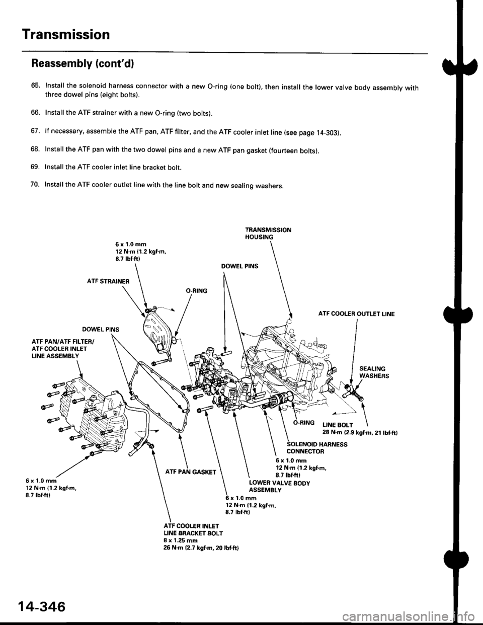
Reassembly (cont'dl
65 lnstall the solenoid harness connector with a new O-ring (one bolt), then install the lower valve body assembly withthree dowel pins (eight bolts).
66. Install the ATF strainer with a new O-ring (two bolts).
67. lf necessary, assemble the ATF pan, ATF filter, and the ATF cooler inlet line (see page 14_303).
68. Install the ATF pan with the two dowel pinsand a new ATF pan gasket (fourteen bolts).
69. Install the ATF cooler inlet line bracket bolt.
70. Installthe ATF cooler outlet line with the line bolt and new sealing washers.
6x1.0mm12 N.m 11.2 kgf.m,8.7 rbtft)DOWEL PINS
ATF STRAINER
DOWEL PINS
ATF PAN,/ATF FILTER/ATF COOLER INLETLINE ASSEMELY
@
@
C4
CONNECTOE
6x1.0mm12 N.m {1.2 kgf.m,8.7 tbtftl6x1.0mm12Nm11.2kgl.m,8.? tbf.ft)
LOWER VALVE BODYASSEMBLY
6x1.0mm12 N.m 11.2 kgf.m,8.7 tbt.ft)
ATF COOI.ER INI.ITLINE BRACKET BOLTI x 1.25 mm26 N.m (2.7 kgt.m, 20 lbf.ft)
ATF COOLER OUTI.IT LINE
14-346
Page 1023 of 2189
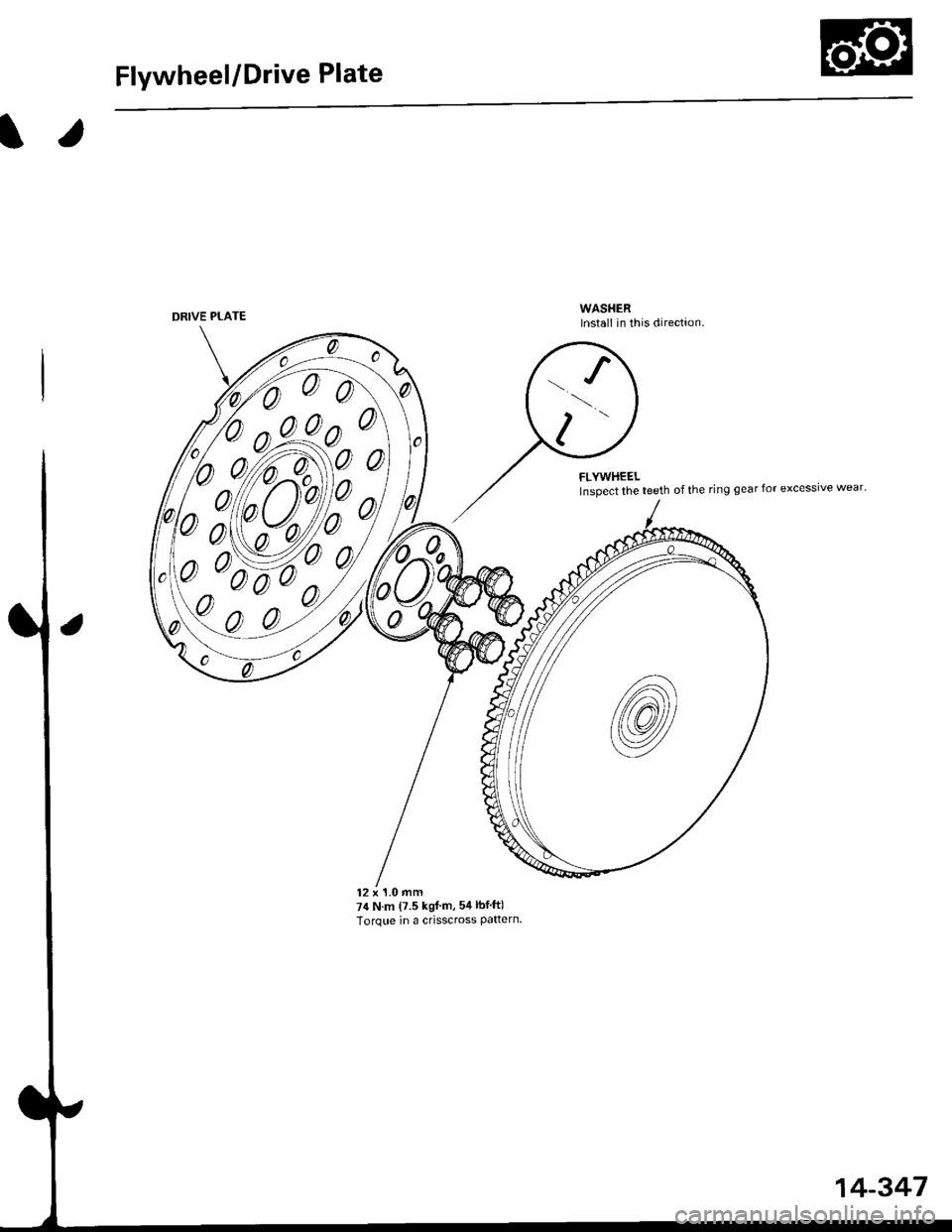
Flywheel/Drive Plate
DRIVE PLATE
/,1vl
a
o0
a9
WASHERInstall in this direction.
FLYWHEELlnspect the teeth of the ring gear for excessive wear'
../
.t
12 x 1.0 mm74 N.m (7.5 kgf.m, 54lbfft)
Torque in a crisscross Pattern
Page 1025 of 2189
l.
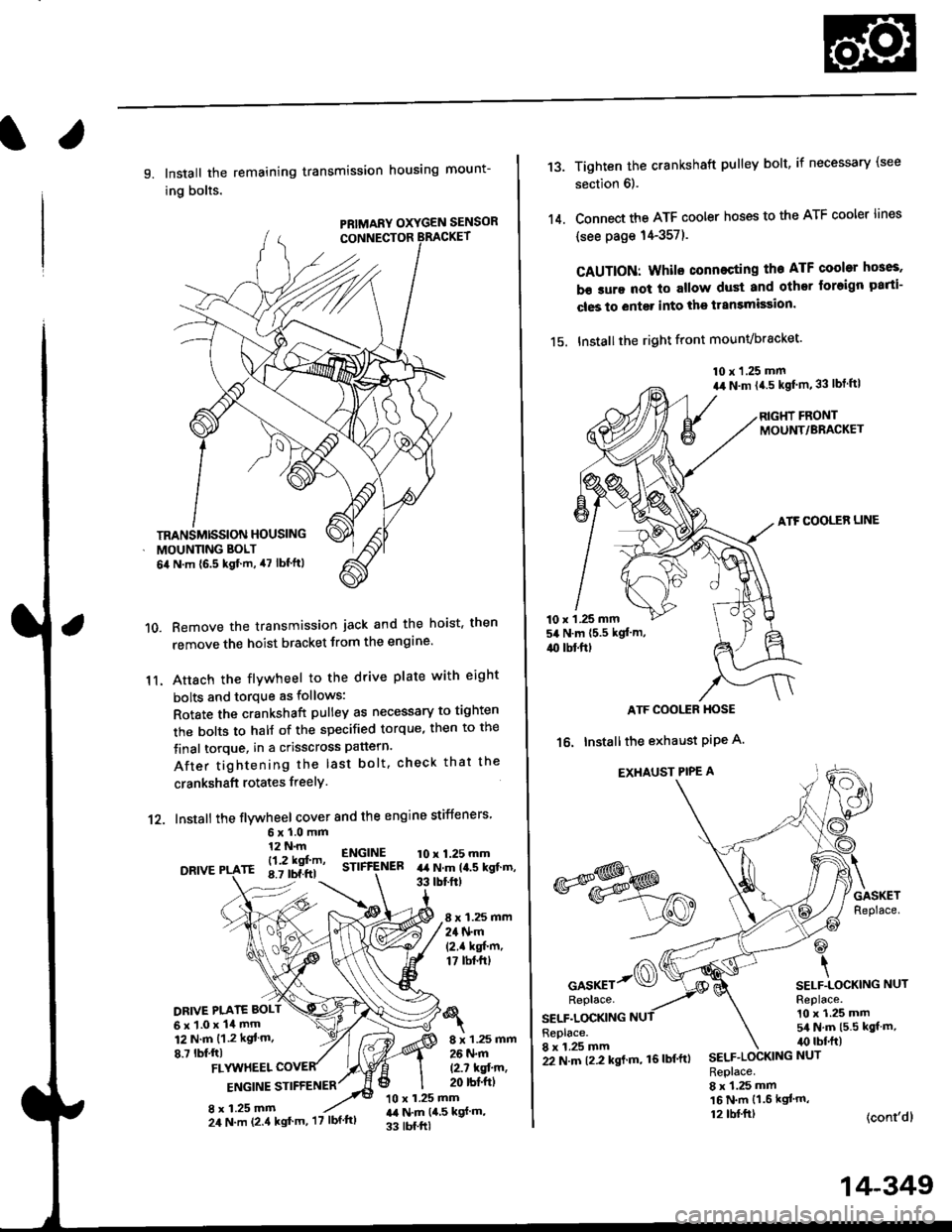
9. Install the remaining transmission housing mount-
ing bolts.
PRIMARY OXYGEN SENSOR
Remove the transmission jack and the hoist. then
remove the hoist bracket from the engine'
Attach the flvwheel to the drive plate with eight
bolts and torque as follows:
Rotate the crankshaft pulley as necessary to tighten
rhe bolts to half of the specified torque, then to the
final torque, in a crisscross pattern.
After tightening the last bolt. check that the
crankshaft rotates freelY.
10.
11.
12. Install the flywheel cover and the engine stiffeners
DRIVE
6xl.0mm12 N.m
- l12 kgf'm'rE 8.7 tbf.ftl
ENGINESTIFfENEB10 x 1.25 mmart N.m la.s kgt.m,33 tbtftt
8 x 1.25 mm24 N.m(2.1 kgf'm,17 tbt.ftt
DRIVE PI.ATE BOLT
6x1.0x14mm12 N.m {1.2 kgt m.
8.7 lbf,ftl8 x 1.25 mm26 N.m
12.7 kqfin,20 rbt'ftlFLYUTHEEL
ENGINE STIFFENER
8 x 1.25 mm10 x 1.25 mmr,a N.m {4,5 kgf m,
33 tbf.ftl
TRANSMISSION HOUSING
MOUNNNG BOLT
6il N.m {6.5 kgf.m, 47 lbf'ftl
24 N.m (2.4 kgt'm, '17 lbf'ftl
22 N.m t2.2 kgl m, 16lbf'ftl
14-349
13.
14.
Tighten the crankshaft pulley bolt, if necessary (see
section 6).
Connect the ATF cooler hoses to the ATF cooler lines
(see page 14-357).
CAUTION: Whilo connecting the ATF cooltr hGes,
b€ sure not lo allow dust and other loreign parti-
cles to entg. into the transmission.
15. Installthe right front mounvbracket'
10 x 1.25 mm
a,r N.m {4.5 kgf'm,33 lbt ftl
RIGHT FRONTMOUNT/BRACKET
ATF COOLER LINE
10 x 1 .25 mm54 N.m {5.5 kgt'm,
4{) tbl.ftt
ATF COOI,TR HOSE
16. Installthe exhaust PiPe A.
EXHAUST PIPE A
GASKETReplace.
@
\SELF.LOCKING NUTReplace.10 x 1.25 mm5/a N.m {5.5 kgt m,irc lbf.ft)
(cont'dl
*s$o
oor*rr-@Replace.
SELF.LOCKINGReplace.8 x 1.25 mmSELF.LOCKING NUT
Replace.8 x 1.25 mm16 N.m {1.6 kgl'm,12 tbl.ftt
Page 1026 of 2189
Transmission
17.
Installation (cont'd)
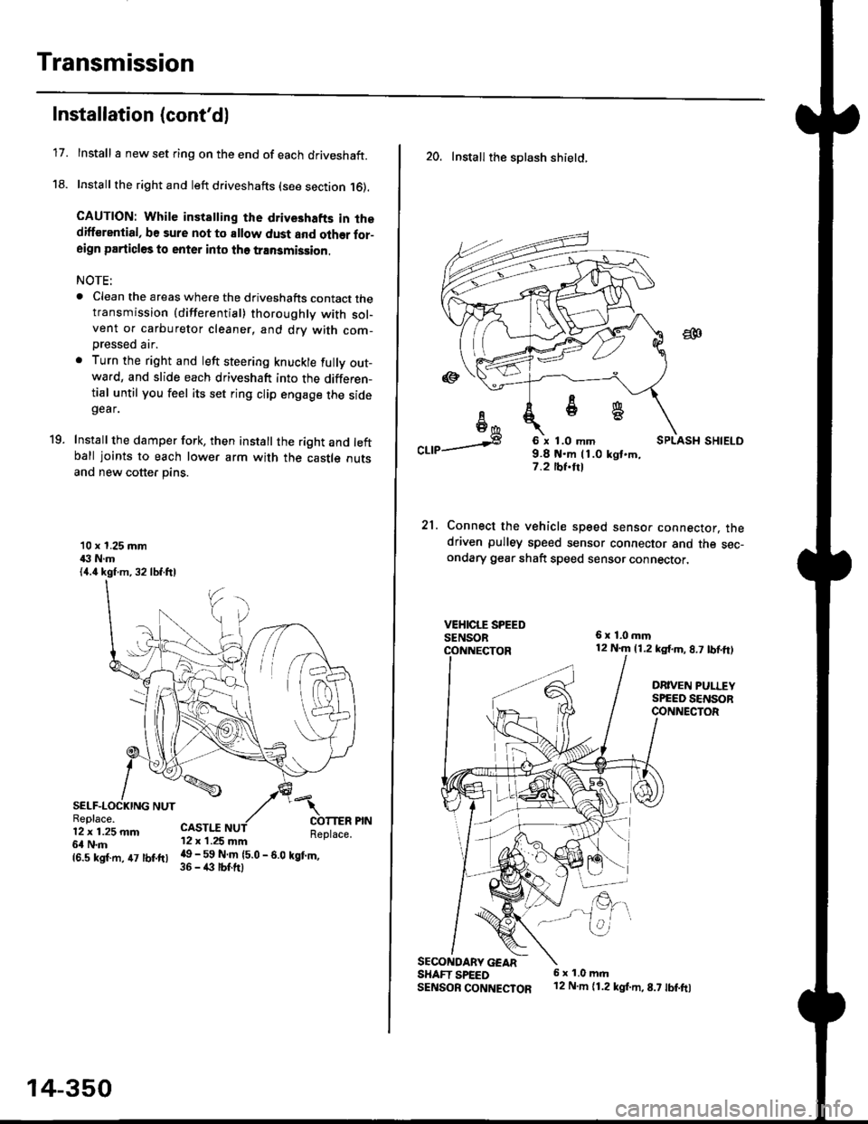
Install I new set ring on the end of each driveshaft.
Install the right and left driveshafts (see section 16).
CAUTION: While instatling the drive3hafts in thedifferential, be sure not to allow dust and olher for-aign particles to enter into tho transmission.
NOTE:
. Clean the areas where the driveshafts contact thetransmission {differential} thoroughly with sol-vent or carburetor cleaner, and drv with com-
Dressed air.
. Turn the right and left steering knuckle fully out-wa.d, and slide each driveshaft into the differen-tial until you feel its set ring clip engage the sidegear.
Install the damper fork, then install the right and leftball joints to each lower arm with the castle outsand new cotter pins.
19.
10 x 1.25 mm43 N.m{4.4 kgf.m, 32 lbf.ftl
SELF-LOCKING NUTReplace.12 x 1.25 mm6l N.m
CASTI.I'12 x 1.25 mm
{6.s ksr.m. 47 tbr.ftr l! _ ll ffiteo
- s.o tet'.,
14-350
20. Install the splash shietd.
aa
I6I6*
"a,a s
21.
SECONOARY GEARSHAFT SPEEDSENSOB CONNECTOR
6 x 1.0 mm9.8 t{.m 11.0 kgt.m,7.2 tbf.trl
Connect the vehicle speed senso. connector. thedriven pulley speed sensor connector and the sec-ondary gear shaft speed sensor connector,
6x1,0mm12 N.m {1.2 kg{.m, 8.7 tbf,ft)
DRIVEN PULLEYSPEED SENSORCONNECTOR
E.
6 x 1.0 m.rl'12 N.m {1.2 kg{.m,8.7 tbf.fo
Page 1027 of 2189

22. Install the shift cable end on the control lever, and
install the shift cable on the shift cable bracket'
CAUTION: Take care not to bend the shift cable'
23. lnstall the clip in the direction shown.
LOCKNUT
SHIFI CABLE 29 N m {3.0 kg{ m, 22lblftl
SHIFT CABLEERACKET
WASHERIPLASTIC)
CONTROL LEVER
24, Connect the solenoid harness connector. the drive
pulley speed sensor connector. and the ground
cable terminals.
6x1.0mm12 N.m {1.2 kgf.m.8,7 rbtft)
GROUND CABLETERMINAL 6x1.0mm
GROUNDTERMINAL
12 N.m {1.2 kgf'm,8.7lbtfrl
DRIVE PULLEYSPEED SENSORCONNECTOR
SOLENOID HARNESS
CONNECTOR
25. Connect the starter motor cable on the starter motor.
and install the cable holder.
NOTE: When installing the staner motor cable. make
sure that the crimped side of the ring terminal is
facing out (see section 23).
STARTEB
BMOUNTING NUT
9 N.m (0.9 kgf m,7 lbf ft)
26. Install all removed connectors and clamps'
27. Install the distributor.
28. Install the intake air duct and air cleaner housing
29.
assemDly.
Refill the transmission with the recommended
Genuine Honda CVT Fluid (see page 14-2991
CAUTION: While filling the CvT Fluid, bs surs not io
allow dust and other fotoign particles to entor into
the transmission.
Connect the battery positive (+) terminal first, then
the negative (-l terminal to the battery'
Check the ignition timing (see section 23).
Start the engine. Set the parking brake, and shift the
transmission through all gears three times Check
shift cable adjustment (see page 14-355).
Check the front wheel alignment (see section 18)
Let the engine reach operating temperature (the
radiator fan comes on) with the transmission in lXl
or E position, then turn it off and check fluid level'
Perform the start clutch calibration procedure on
page 14-293.
Road test as described on pages 14-296 and 14-297
30.
31.
34.
36.
STARTER MOTOR
14-351
Page 1028 of 2189
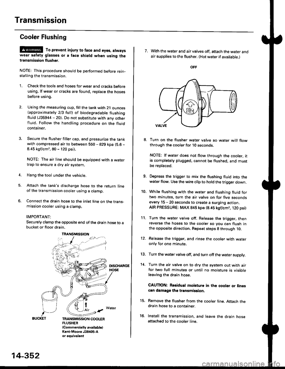
Transmission
Gooler Flushing
@ To prevent iniury to face and eyes, alwayswear safety glasses or a tace shield when using thetransmission flusher.
NOTE: This procedure should be performed before rein-stalling the transmission.
'1. Check the tools and hoses for wear and cracks before
using. lf wear or cracks are found, reDlace the hoses
before using.
4.
Using the measuring cup. fill the tank with 2,1 ounces(approximately 2/3 full) of biodegradable flushingfluid (J35944 - 20). Do not substitute with any otherfluid. Follow the handling procedure on the fluidcontatner.
Secure the flusher filler cap, and pressurize the tankwith compressed air to between 5S0 - 829 kpa (5.6 -
8.45 kgf/cm'�, 80 - 120 psi).
NOTE: The air line should be equipped with a watertrap to ensure a dry air system,
Hang the tool under the vehicle.
Attach the tank's discharge hose to the return lineoi the transmission cooler using a clamp.
Connect the drain hose to the inlet line on the trans-mission cooler using a clamp.
IMPORTANT:
Securely clamp the opposite end ofthe drain hose to abucket or floor drain,
t
TRANSMISSION COOLERFLUSHER{Commercially available)Kent-Moore J384O5-Aor oouivalent
TRANSMISSION
14-352
7. With the water and air valves off, attach the water andair supplies to the flusher. (Hot water if available.)
8. Turn on the flusher water valve so water will flowthrough the cooler for 10 seconds.
NOTE: lf water does not flow through the cooler, itis completely plugged, cannot be flushed, and mustbe replsced.
9. Depress the trigger to mix the flushing fluid into thewater flow. Use the wire clip to hold the trigger down.
'10. While flushing with the water and flushing fluid fortwo minutes. turn the air valve on for five secondsevery 15 - 20 seconds to create a surging action.AIR PRESSURE: MAX 845 kpa (8.45 kgflcmr, 120 psi)
11. Turn the water valve off. Release the trigger, thenreverse the hoses to the cooler so you can flush inthe opposite direction. Repeat steps 8 through 10.
12. Release the trigger. and rinse the cooler with wateronly for one minute.
13, Turn the water valve off, and turn off the water supply.
'14. Turn the air valve on to dry the system out with airfor two full minutes or until no moisture is visibleleaving the drain hose.
CAUTION: Rosidual mobturo in the qooler or linescln damage the transmission,
15. Remove the flusher from the cooler line. Attach thedrain hose to a container.
16. Install the transmission. and leave the drain hoseattached to the cooler line.