100 HONDA CIVIC 2000 6.G Workshop Manual
[x] Cancel search | Manufacturer: HONDA, Model Year: 2000, Model line: CIVIC, Model: HONDA CIVIC 2000 6.GPages: 2189, PDF Size: 69.39 MB
Page 1954 of 2189
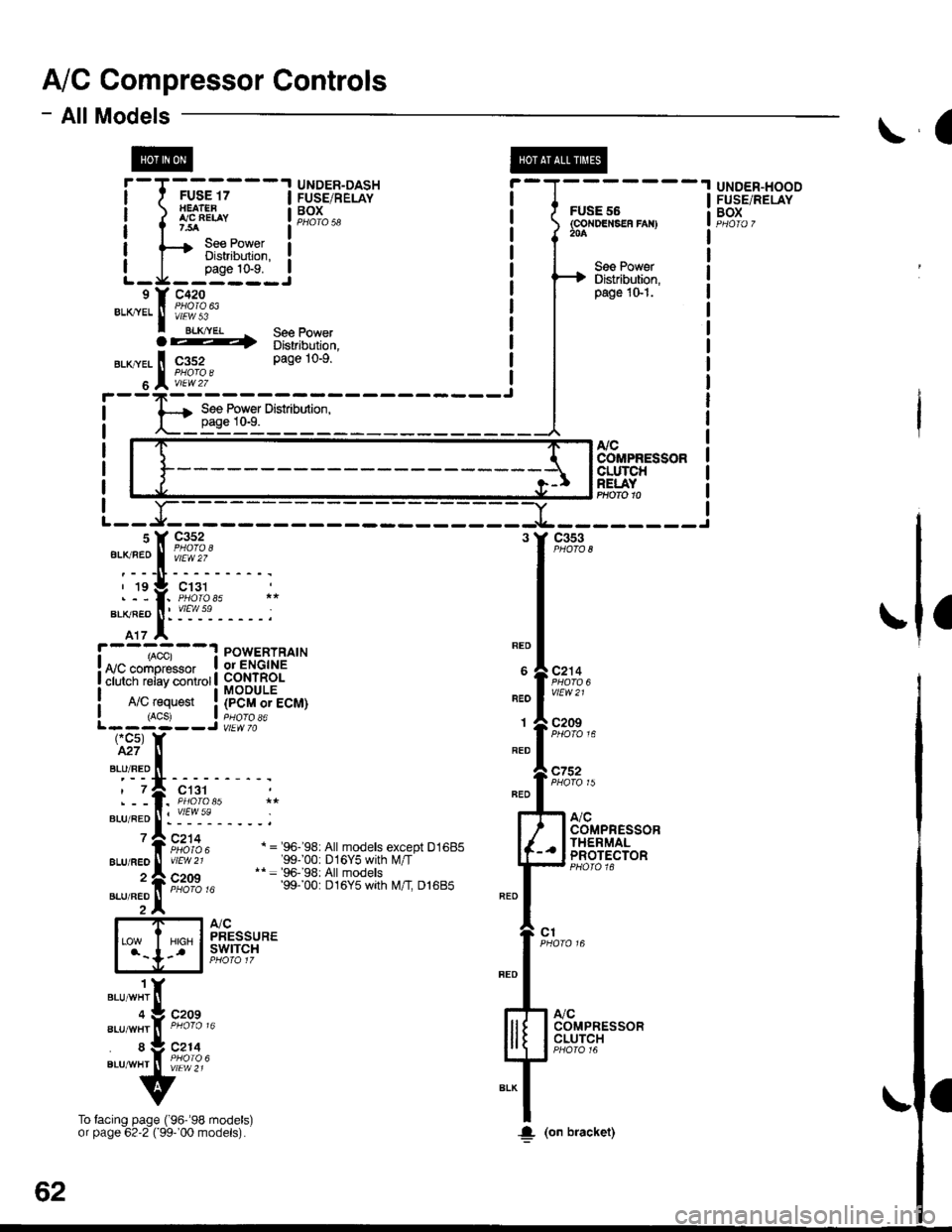
A/C Compressor Controls
- AllModels
cc5)M7
BLU/RED
?
\a
@
&cCOMPRESSORCLUTCHRELAYPHOfO 10
a
! ,acc, : POWERTRATN! arn.^-^,o..^, I or ENGINE
! ii i"i-iiii"v i.,ii.r | fi 3$18.
I A/C request ! (pCM or ECM)I (ACSJ a pHOrO a6L------J vtEw 70
REO
BEO
1
RED
BLU/FEO
2
BLU/FEO
ct31
:"1'!i'------;
Fi:rz, a ='e6-'s8: A|| moders except D1685vtEw 21 '99100: D16Y5 with l\illT'* = 96-'98: All models
ir'iio ," 99. 00: Dt6y5 wth t\4/t Dl6Bb
atcPRESSUREswtTcH
c752
c1
".,n""t 1(
".r-".rf, "tA% "
"."-:,fi tfr,]4.
v
To facing page ('96''98 models)or page 62'2 ( 99-'00 models).
-Yl
-t---------Jc353
c2'14
vtEW21
c209
A,/CCOMPRESSORCLUTCH
COMPRESSORTHERMALPROTECTOR
UNDER-HOODFUSE/RELAYBOXf-T-*-'.T'---l H53.',EPA?' i-l-------
i iflH* !F,?r",, i f6F"'.i:.",",
| tsBi":J;"#il ! a T| | oaoe 1o-9. ! I I See PowerL_J1_j:_-_j ! H Distriburion.e Y c42o i I
pase 1o-1.
***
f ifi"l'
^ see power ! |
62
!(on bracket)
Page 1964 of 2189
Rear Window Defogger
- How the Circuit Works
'96198 Models
Voltage is applied at all limes through tuse 50 to the
rear window detogger relay (contacts). With the
ignition switch in ON (ll), voltage is applied through
tuse 16 to the rear window defogger switch.
When you turn the switch ON, voltage is applied to
the defogger timer circuit. The timer circuit supplies
voltage to the rear window defogger relay (coil). The
relay energizes and supplies voltage to the rear
window defogger. The defogger grid then heats the
rear window to remove any condensation from the
glass.
The defogger timer circuit will automatically turn off
the rear window defogger after about 25 minutes.
Refer to the Service Manual (Section 23, Electrical)
for specific tests or troubleshooting procedures.
'99100 Models
Voltage is applied at all times through fuse 50 to the
rear window delogger relay (contacts). With lhe
ignition switch in ON (ll), voltage is applied through
fuse 16 to the heater control oanel.
When you turn the rear window defogger switch
ON, a signal is sent to lhe defogger timer circuit
built-into the heater control oanel. The timer circuit
supplies voltage to the rear window defogger relay
(coil). The relay energizes and supplies voltage to
the rear window defogger. The defogger grid then
heats the rear window to remove anv condensation
from the glass.
The defogger timer circuit will automatically turn otf
the rear window defogger after about 25 minutes.
Refer to the Seryice Manual (Section 23, Electrical)
for specific tesls or troubleshooting procedures.
64-2
I
a
a
Page 1966 of 2189

See Wiper,ryVasher
@
FUSE 30l|lslFl,|tEl{luotfT3
UNDER-DASHFUSE/RELAYBOX
I
t
I
I
I
.1 1
-t
\
\\
Sea PowerDistfibution,pag€ 10-5. iz
FUSE 15ALTEi}IATORsP 8S$80n?.54
A8
7'5A soe Headtight sss Power- Switch, Distibution,page 100-t. pags 1G7. foINTEGRATEDCONTNOLUNIT
vEw af
\
\
\
t
I
,
I
I
I
a-------
FUSE 26FR \I/IP€gFi WASTIEF204
Ught8.ONnemhderCircrti
lfllsnl|literWip6r RelayCircuit
Combin€dl,Ylper/WarhotCireuit
*I "'r
II
II
-----[---t-----
""r,".* I ".u-"r l
tt\--
See WiperMasher
70-1
Page 1980 of 2189
Gauges (cont'd)
- How the Gircuit Works
When the ignition switch is in ON (ll) or START (lll),
battery voltage is supplied through fuse 25 to the
gauges in the gauge assembly.
Speedometer and Odometer
The odometer and soeedometer drive circuits
receive pulses from the vehicle speed sensor
(VSS). The pulse rate increases as the car
accelerates. The frequency and duration of these
input pulses are measured and displayed by the
speedometer, odometer and tripmeter.
Tachometer
The tachometer drive circuit receives pulses from
the ignition control module (lCM) in the distributor
assembly or the ECM/PCM. The solid-state
lachometer then displays these pulses as engine
speed. For each 200 pulses per minute from the
ignition control modul€ (lCM) or the ECM/PCM, the
tachometer displays 100 RPM.
Engine Coolant Temperature Gauge
The engine coolant temperature gauge has two
intersecting coils wound around a permanent
magnet rotor. Voltage applied to the coils, through
fuse 25, generates a magnetic lield. The magnetic
field, controlled by the coolant temperature sending
unit, causes the rotor to rotate and the gauge
needle to move. As the resistance in the sending
unit varies, current through the gauge coils
changes. The gauge needle moves toward the coil
with the strongest magnetic field.
The 6ngine coolant temperature sending unit's
resistance varies from about 137 ohms at low
engine temperature to between 3H6 ohms at high
temperature (radiator fan running).
Refer to the Service Manual (Section 23, Electrical)
for specific tests or troubleshooting procedures.
81-2
(
Fuel Gauge (All except cX)
The fuel gauge has two intersecting coils wound
around a permanent magnet rotor. Voltage applied
to the coils, through tuse 25, generates a magnetic
field. The magnetic field, controlled by the fuel
gauge sending unit, causes the rotor to rotate and
the gauge needle to move. As the resislance in the
sending unit varies, current through the gauge coils
changes. The gauge needle moves toward the coil
with the strongest magnetic field.
The fuel gauge sending unit's resistance varies
from about 2-5 ohms at full, to about 110 ohms at
empty. When you turn the ignition switch off, the
gauge remains at the last reading until you turn the
ignition switch to ON (ll) or START (lll) again,
Refer to the Service Manual (Section 23, Electrical)
for specific tests or troubleshooting procedures.
Fuel Gauge (GX)
The fuel gauge has two intersecting coils wound
around a permanent magnet rotor. Voltage applied
to the coils, through fuse 25, generates a magnetic
field. The magnetic field, controlled by the PCM,
causes the rotor to rotate and the gauge needle to
move. The PCM calculates the gas quantity in the
fuel tank by using the fuel pressure value detected
by the tuel tank pressure sensor and the fuel
temperature value detected by the fuel tank
temperalure sensor, and outputs the signal to the
gauge assembly. The gauge needle moves toward
the coil with the strongest magnetic field.
When you turn the ignition switch off , the gauge
remains at the last reading until you turn the ignition
switch to ON (ll) or START (lll) again. When the
PCM detects a malfunction with the fuel pressure or
temperature, or detects a gas leak, the PCM
reduces the fuel meter to 0.
Refer to the Service Manual GX Supplement
(Section 11 , Fuel and Emissions) for specific tests
or troubleshooting procedures.
a
a
Page 1987 of 2189

Rear WiperMasher
'l'
1r
F
I
I
I
I
3('1:2)
t:
!l
iL
BLU
6GFN/BLK
4GFN/BIK
1FEO
FUSE 3(RR WPENRn waaHERl
c423 8PHOfO 58vtEw 3
GRN
1
Gf,N/BLK
GRIi3LT GFN
4LT GRN
(t1: 13)
LTGFN4(*1: 3)LT GAN
t
9i:;"* Lr.RN/BLXvlEw 30
c205
'1 = '96-'98 models
*' = Male - Femaleterminals reversedlor '99-'00 models
LT GRN/ELK
REARwtNoowWIPERMOTOR
GFN
4{.1: 6)
GRN
c551PHOTO 63
c562 **PHOTO 101
c607PHO|O 112Lf GRN/BLK
4
ge€ QroundDistdbr{ion,page 1+'12.
LI GRN/BLK
2
BLX
>-ra
c607PHOTO 112vtEw I
cs62 *
vlEW 42
c401
c767 6PHOTO 126
c607
vlEw 9
c562 ri
vtEw 42
c40'l
B (C427\
c767
(.1r 14)
".- I lrcFN/BlK
t G761
lPhofo 132'98100 oodsls)
a
REARwtNDowWASHERMOTOR
s (c427'l
S€e GoundDietrlbution,page t4"6.
LT GFN/BLK
BLK
BLKc205
So€ GroundDistribution,page 14-4.
II
L__l+: G40l
a
92
--f
Page 1988 of 2189
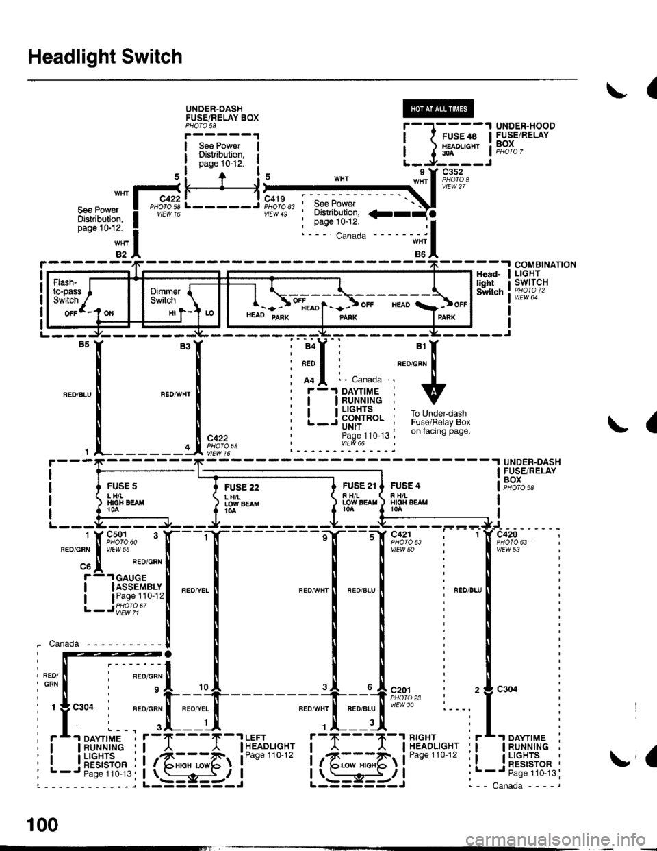
Headlight Switch
(
UNOER-OASHFUSEiRELAY BOXPHOTO 58
Sse PowerDisiribution,page 10-12-
UNDER-HOODFUSE/RELAYBOX
H
FUSE 22L H/ILOIY SEAflt0a
COMBINATIONLIGHTswtTcHHead-lightSwltch
L-----J'SeePower' Distribution,
: Page 10-12.
a
{
UNDER-DASHFUSE/RELAYBOXFUSS 2tF H/LLOW EgAtl
FUSE 4R TIILHIG|{ AEAMt0A
vtEw 53
_ ___:==
1-sr*r"
_
l_-.__
_,_.
it:
".0-", i ".o ".u I i ".o u.,
iti
Iti
llr
lli
lli
--'l --u{.sao,l,. i 2
neourrr I nroerul'/Ftr'o :---,
,.|,___ui
il--Tll''%i'sr"' ii
it@4li**"""li-; s-i5-r i .
I
I
i-t-;;l
1 J lff*n"' IL-.J----J
nrrl'?;Ii
ffif'illi! i
*itn12
HI
- - ) ot[*o1- -] ot. "roo a]ot.HEAD PAnK I panx IPAnK
!a
- -I DAYTIME
IRUNNINGI LIGHTS
! RESTSTOR'- Paqe 110-13
100
Page 1989 of 2189

UNDER.DASHFUSE/RELAYBOXPHOTO 58
I
I
I
I
I
I
FUSE 32tpE SE UGfiTStan r|{rs7,54
r--1 l ?EqnATEOI uohts I co rRoL; OFI I UNIT
! input ! im?,t
I
1f12)
To Under-dashFus€/Rglay 8oxon n6xl pag€.
-J---------rt--- ----Jc4r9 15 Y C501 c927PHOfO 6iOPTIONCONNECTORPHOTO 62
nEo/ALK
REO/ALK
* = '96-'98 models
*1[
"-"'['**,.1
_[ *[ ,*,
, FED/
I t:t t;t I
I l:l I ll IL--J ; L--J .L--J
HAZARD , REAR ' CRUISEWARNING. WINDOW :CONTROLSwITcH . DEFoGGER; MAINPage 114-1; SWITCH ' SWITCHvtEv/ 32 , Page114-1 'Pago114-1
c507(Ierminals11n6)
vtEw 56REO/EIK
14
RED/BLK
C't40PHOTO El
c723PHOfO 138
r--1 ;-r
| |ii | il || | | ll I: : A"rr GEAR !------J L--J
EEil'J",- p$i+bd'i 3333fi".' ilB?o'?u"."PANEL Eli"ira Page114 (96-'98 models)Page 114 PHoro 6, Page 1 14.1pHOfO 71 VIEW 71 pHOfO 73PHO|O 1i7 (g9'@l V|EW 6AwEtt/ 41 otv/Ew761ee-oo)
irril?.rJllPage 114-1PHOfO 13/vtEw 74
tl
tl
OASH LIGHTBRIGHTNESSCONTROLLERPage 114-1
(cont'd)
FIJSE l0
100-1
Page 1990 of 2189

100-2
Headlight Switch (cont'd)
-.I UNDER.DASHRom UderdashFur€/Bslay 8ox orprevrous prge.
- - -ri-Y c421 13 Y C5s1'- ll PHoro 63 ll esoro6J
neoialx I u/EW 50 BEDelfi i v'Edu7
'f ---- Hatchback l, Coupe and Sedan
c2o1 : I !'--'l Itlt5i:^- :i"'oYizt i i Iri"Je'tl
i l3pfif.l-"o."-i ".o,".*l =,a,e.Fema,e, ll L--J pe6161ja , ll terminals reversed
: tr_ _ _ _ _ _ _ _ _ _Y::_ _ _ _ _:
c202PNO|O 23ytEw 1
LEFTBRAKELIGHT/TAILLIGHTPage 110-5
9('99100 models 18)
FED/BLK
RIGHTTAILLIGHTPage 110-5
c562 .
vtEw42
c605
wEw a
RIGHTBRAKELIGHT/TAILLIGHTPage 110-5
LEFTLICENSEPLATELIGHTPage ! 10-5
for '99-'00 models
FUSE/RELAYBOX
1(cruise 3)c604 5
FEO/BLK
"ao,"a* |
I
/---lI \---t
LEFTTAILLIGHTPage 110-5
\;,,
LEFT FRONTPARKING/TURNSIGNALLIGHTPage 110-2
RIGHTLICENSEPLATELIGHTPage 110-5
,rUrOO ro.",. ?, I
r-\\_,
".,"-[TI
RIGHT FRONTPARKING/TURN SIGNALLIGHTPage 1l0-2
Page 1991 of 2189

FED/ALX
I(GX 6)(96-98 Sedans except GX 14)(99100 models except GX 18)
FED/BLX
t=Male-Female
terminals reversedfor99-00 models
REO/ALK
All except99r00
Sedans
c562 r
vlEw 42
FED/BIX
All Excâ")
I
\
)
FED/ALX
I(GX 6)('96-'98 Sedans except GX 14)('99100 models except GX 18)
FED/BLX
t=Male-Female
terminals reversedfor'99-'00 models
REO/ALK
All except'99r00
Sedans
c562 r
vlEw 42
FED/BIX
All Exc€pt'99'00
Sedang
FED/BLX
All except'99100 '99'00
Sgdans S€dans
'99'00
godans
RIGHTINNERTAILLIGHTPage 110-4
c617
FED/ALK
'99r00
Sedans
All exc€pt'99"'00
Sedans
'99-'00
Sodans
"'*.jx""'r{ "*^*".*:trt
"ao,"a" Iql
\/
LEFTINNERTAILLIGHTPage 110-4
c613
LEFTBRAKELIGHT/OUTERTAILLIGHTPage 110-4
RIGHTBRAKELIGHT/OUTERTAILLIGHTPage 110-4
c605c604 3
FED/BLKFED/ELK
FEO/B!K
(99-'00Sedans 1)
RED/BLX
Sedans 'l)
\
RIGHT INNERBRAKELIGHT/TAILLIGHTPage 110-3
LEFTLICENSEPLATELIGHTPage 1 10-3or 110-4
RIGHTLICENSEPLATELIGHTPage 110-3or 110-4
\/
RIGHTOUTERBRAKELIGHT/TAILLIGHTPage 1 10-3
LEFT INNERBRAKELIGHT/TAILLIGHTPage 110-3
LEFTOUTERBRAKELIGHT/TAILLIGHTPag€ 110-3
Page 1992 of 2189

Back-Up Lights
- Coupe and Sedan
*=Male-Female
terminals reversedfor '99100 models
!, (
I
10
YEURED
UNDER.DASHFUSE/RELAYBOXPHOfO 58
T
I:c,
x
FUSE 19EACK UF UGH'S754
-----Jc419
A/T except CW
YEUNEO
15('99-'00 except D16Y5 6)
YEL
2
GRN/BLK
c'13't
vlEw 59
c124PHOTO 31PHOrO 150 (Si)
vtEw 59
BACK-UPLIGHT SWITCHClosed withtransmissionin reverse.
PHO|O 75r (SD
cl24
PHOTO 15015)
3 ^ C433
yeL a VIEW 41.I A/T GEAR:+f't::
tDa
l!-iAf
;;-'i-
""",":lt
'lrry
lD.
ly*Af
:t
| | | ?osllrgN
i l"-3.^' a "s#[c#i "j!*{b. i*'o*
GFN/BLK
GRN/BIX
14('99100 except 016Y5 18)
CRN/BL(
aplF--1 i';".;t---'
o * "",0::","
o"n,".-*
[
u't' o '
!(
'99-'00
S€dan$
t gg- oo mooers l2ot | #:;",,
, rrr:eS;f""t"-!# I ;; tAll oxcept'9$'oo Sodans
"*^*f,
""::in;;'
ffi,*,,.T
@
GFN/BLK
lo
@FLRI''
"*r
>-rO
@i[TJ+."
RIGHTBACK.UPLIGHT
22
See GroundDistribution,pags 1i1.1t.
".- |
!
I
Ia
I
!G601G601
PHO|O 102 IAX)
110
(