100 HONDA CIVIC 2000 6.G Workshop Manual
[x] Cancel search | Manufacturer: HONDA, Model Year: 2000, Model line: CIVIC, Model: HONDA CIVIC 2000 6.GPages: 2189, PDF Size: 69.39 MB
Page 1126 of 2189

@
\9
o
@aa\
@
o
@
@
@
07GAF - SE00200
07GAF - SE00401
07GAG - SD40700
07JAF - SH201 l0
07JAF - SH20120
07JAF - SH20200
07MAC -")
Special Tools
Ref. No. Tool NumborDescriptionOty Page Reteronc€
o
€)
@
\9
o
@aa\
@
o
@
@
@
07GAF - SE00200
07GAF - SE00401
07GAG - SD40700
07JAF - SH201 l0
07JAF - SH20120
07JAF - SH20200
07MAC - S100200
07746 - 0010500
07749 - 0010000
07947 - 6340201
07965 - SB00100
07965 - 5800200
07965 - SD90100
07974 - SA50700
Hub Assembly Guide Attachment
Hub DivAssembly Base
Ball Joint Boot Clip Guide
Hub Dis/Assembly Pilot, 38 mm
Hub Dis/Assembly Shaft,22.4 x25.4 mm
Ball Joint Remover Base
Ball Joint Remover,2S mm
Attachment, 62 x 68 mm
Driver
Driver Attachment
Eall Joint Remover/lnstaller
Ball Joint Installer Base
Support Base
Ball Joint Boot Clip Guide
,|
1
1
1
1
1
1
1
1
1
1
1
I
1
td- tc
18- 14
18-17
18- 14
18- 14
18-16
18-12, 13
18-14
18- 14
18- 15
18- 16
18- 16
18-15
18-16, 17
o@@.@@
@
o@
1a-2
Page 1139 of 2189
I
NOTE: Wash the knuckle and hub thoroughly in
high flash point solvent before reassembly.
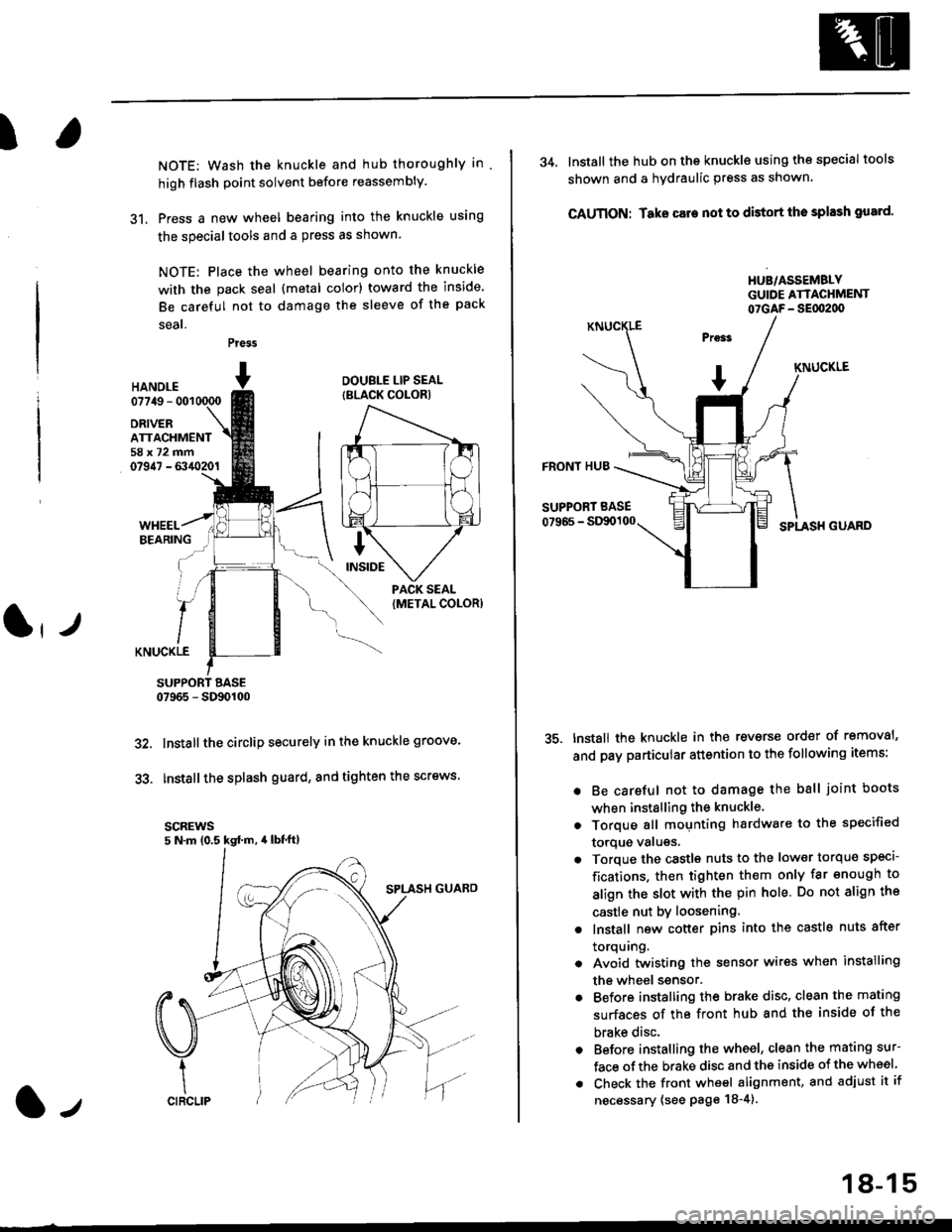
31. Press a new wheel bearing into the knuckle using
the specialtools and a press as shown
NOTE: Place the wheel bearing onto the knuckle
with the pack seal (metal color) toward the inside
Be careful not to damage the sleeve of the pack
seal.
Press
HANOI.E07749 - 001
DRIVERATTACHMENT58x72mm07947 - 6340201
DOUBLE LIP SEAL
{BLACK COLOR)
KNUCKLE
SUPPORT BASE07965 - SD90100
Installthe circlip securely in the knuckle groove'
Installthe splash guard, and tighten the screws.
scREws5 N.m (0.5 kgd m, 4lbt'ft)
32.
33.
l-,
18-15
34. lnstall the hub on the knuckle using the specialtools
shown and a hydraulic press as shown.
CAUTION: Take care not to distort tho splash gusrd'
HUB/ASSEMBLYGUIDE ATTACHMENT07GAF- SEflt2d)
KNUCKLE
FRONT HUB
SUPPORT BASE
07966 - StXx)100SPLASH GUARD
tnstall the knuckle in the reverse order of removal'
and pay particular attention to the following items:
. Be careful not to damage the ball joint boots
when installing the knuckle.
. Torque all mounting hardware to the specified
torque valugs.
. Torque the castls nuts to the low€r torque specl-
fications, then tighten them only far enough to
align the slot with the pin hole. Do not align the
castle nut by loosening.
. lnstall new cotter pins into the castle nuts after
torquing.
. Avoid twistin0 the sensor wires when installing
the wheel ssnsor.
. Before installing the brake disc, clean the mating
surfaces of the front hub and the inside of the
brake disc.
. Before installing the wheel, clean the mating sur-
face ofthe brake disc and the inside of the wheel
. Check the front wheel alignment, and adjust it if
necessary (see page 18-4).
Page 1156 of 2189
![HONDA CIVIC 2000 6.G Workshop Manual Special Tools
Ref. No. I Tool Numbo]DescriplionOty I Page Reference
o07HAE - SG00100
07JAG - SD40100
07914 - SA50001
Brake Spring Compressor
Pushrod Adjustment Gauge
Snap Ring Pliers
19-28, 33
19-22
o](/img/13/6068/w960_6068-1155.png "HONDA CIVIC 2000 6.G Workshop Manual Special Tools
Ref. No. I Tool Numbo]DescriplionOty I Page Reference
o07HAE - SG00100
07JAG - SD40100
07914 - SA50001
Brake Spring Compressor
Pushrod Adjustment Gauge
Snap Ring Pliers
19-28, 33
19-22
o")
Special Tools
Ref. No. I Tool Numbo]DescriplionOty I Page Reference
o07HAE - SG00100
07JAG - SD40100
07914 - SA50001
Brake Spring Compressor
Pushrod Adjustment Gauge
Snap Ring Pliers
19-28, 33
19-22
o@
19-2
Page 1182 of 2189
Rear Brake Galiper
Disassembly (cont'd)
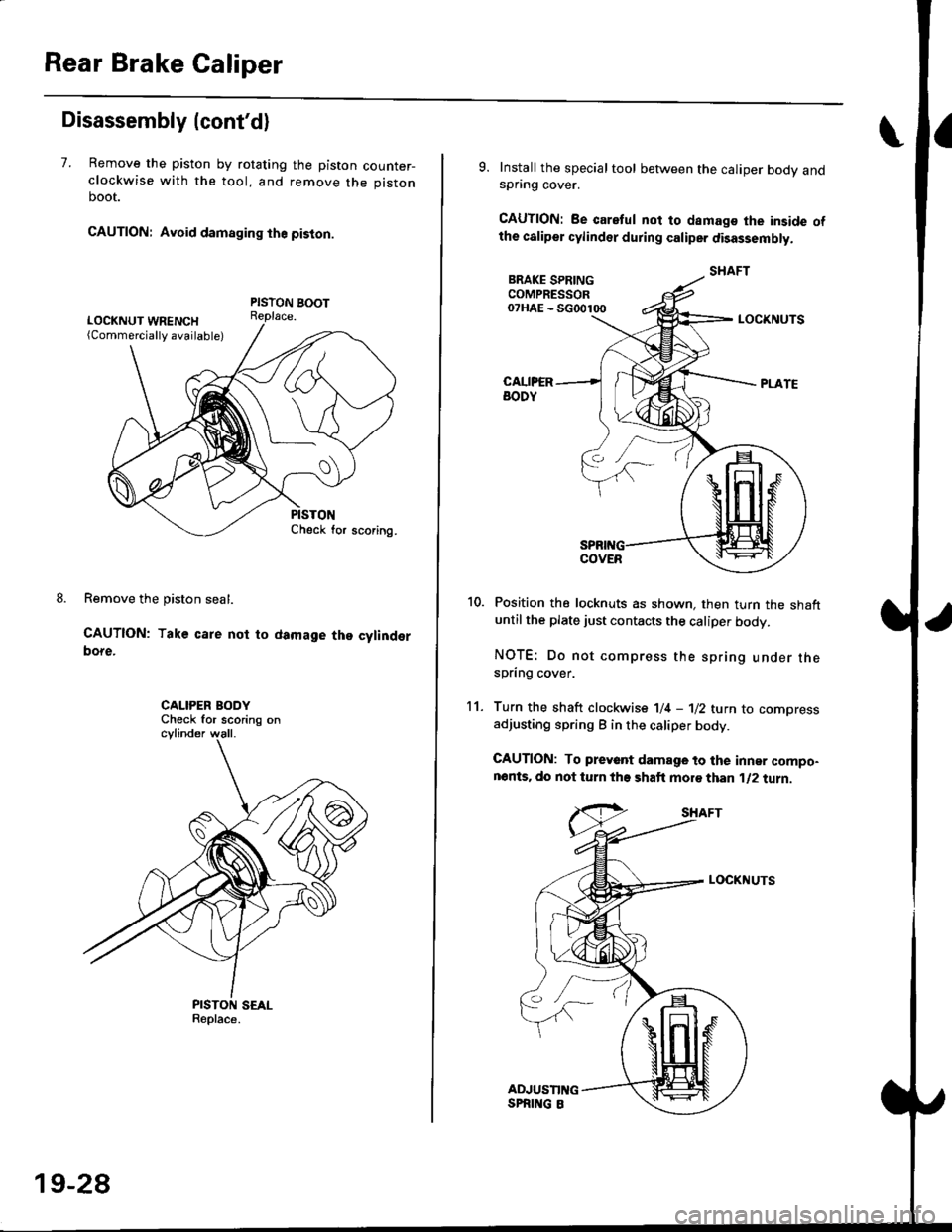
7. Remove the piston by rotating the piston counter-clockwise with the tool, and remove the piston
boot.
CAUTION: Avoid damaging the piston.
PISTON BOOTReplace.
Remove the piston seal.
CAUTION: Take care not to damage the cylinderbore.
CALIPER BODYCheck for scoring on
9. Install the special tool between the caliper bodv andspnng cover.
CAUTION: Be caretul not to damags the inside ofthe caliper cylinder during caliper disassembty.
BRAKE SPRINGCOMPRESSOR07HAE - SG00100
11.
LOCKNUTS
Position the locknuts as shown. then turn the shaftuntil the plate just contacts the caliper body.
NOTE: Do not compress the spring under thespring cover.
Turn the shaft clockwise 1/4 -'ll2 tu.n to comoressadjusting spring B in the caliper body.
CAUTION: To preyant damage to the inner compo-nonts. do not turn the shaft mor€ than 1/2 turn.
SHAFT
LOCKNUTS
PISTON SEALReplace.
ADJUSTII{GSPRING 8
19-28
Page 1197 of 2189
Special Tools
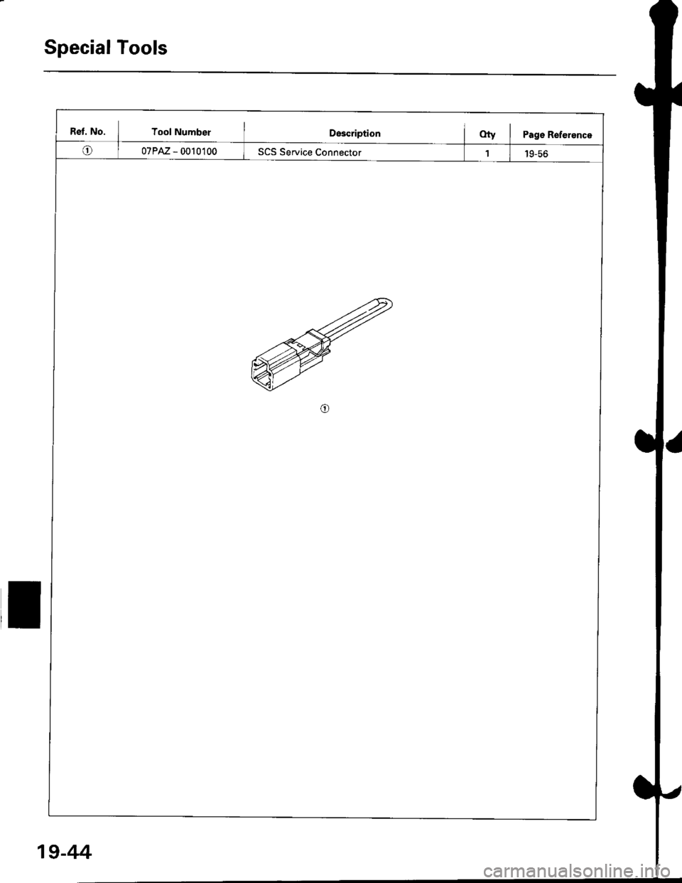
Ret. No. I Tool Number I Description I O,V I page Reference
(!) I 07PM- 0010100 I SCS Service Connector t I 19_s6
19-44
Page 1209 of 2189
Diagnostic Trouble Code (DTCI
Diagnostic Trouble Code {DTC) Indication
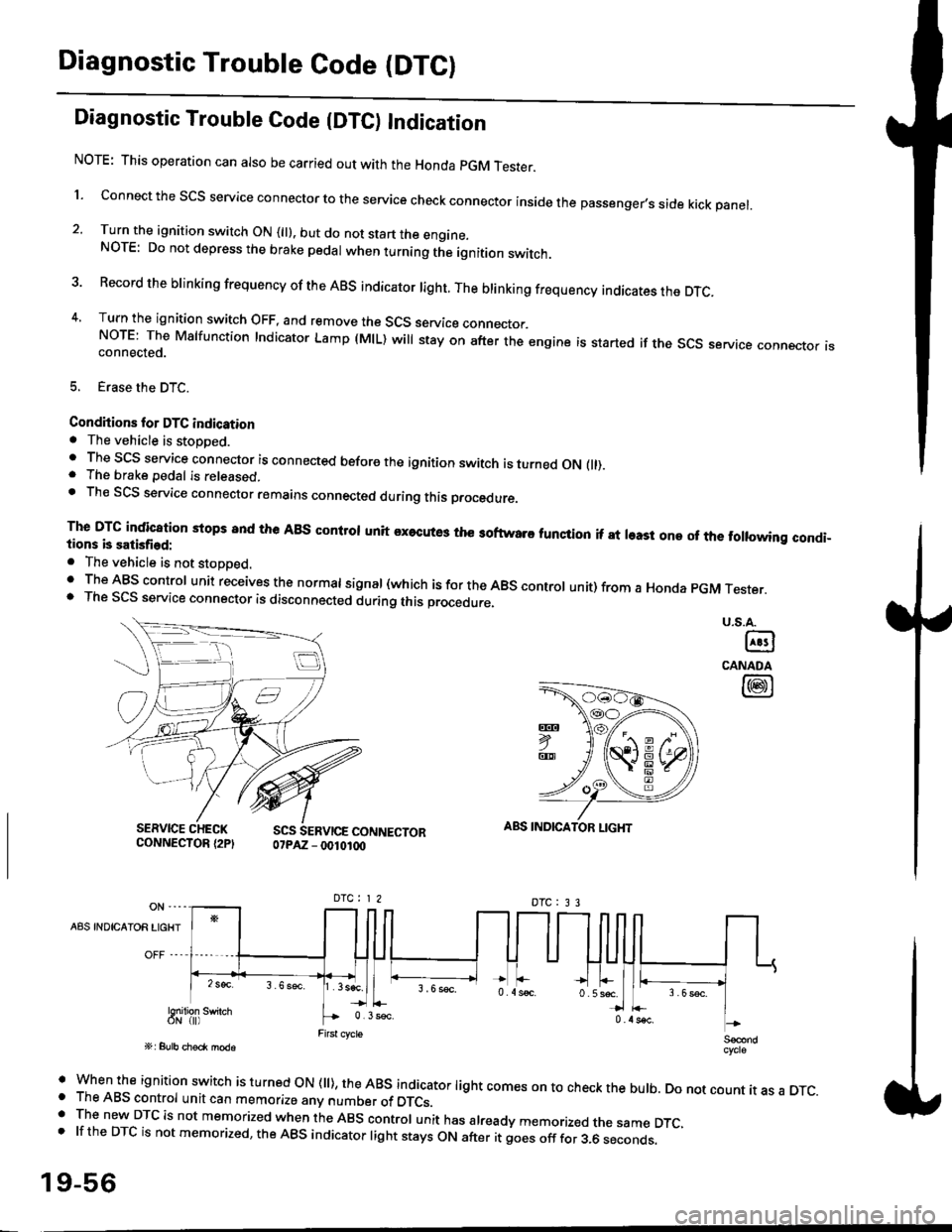
NOTE: This operation can also be carried out with the Honda pGM Tesrer.
l connect the scs service connector to the service check connector inside the passenger,s side kick panel.
2. Turn the ignition switch ON (||). but do not start the engine.NOTE: Do not depress the brake pedal when turning the ignition switch.
3 Record the brinking frequency of the ABS indicator right. The brinking frequency indicates the DTc.
4, Turn the ignition switch OFF, and remove the SCS service connector.NorE: The Mslfunction Indicator Lamp (MlL) will stay on after the engine is started if the scs service connector isconnected.
5. Erase the DTC.
Condhions for DTC indication. The vehicle is stoDDed.. The SCS service connector is connected before the ignition switch is turned ON fll).. The brake pedal is released.. Th€ SCS service connector remains connected during this procedure
The DTG indication stops 8nd the ABs conltol unit executes the softwaro tunqtion if at least one of the following condi-tions b satisfied:
o The vehicle is not stoDoed.' The ABS control unit receives the normat signal (which is for the ABS controt unit) from a Honda pGM Tester.. The SCS service connector is disconnected during this procedu.e,
u.s.A.
@
CANADA
@
SERVICE CHECKCONNECTOR {2PISCS SERVICE CONNECTOR07PAZ - 0010100
ABS INDICATOR LIGHT
DTC : 3 3
A8S INDICAIOR LIGHT
Snilion swirch
' when the ignition switch is turned oN (ll), the ABs indicator light comes on to check the bulb. Do not count it as a DTc.o The ABS control unit can memorize any number of DTCs.. The new DTC is not memorized when the ABS control unit has already memorized the same DTC,.lftheDTCisnotmemorized,theABSindicatorlightstaysONafteritgoesofffor3.6seconds.
19-56
Page 1259 of 2189
tInstallation
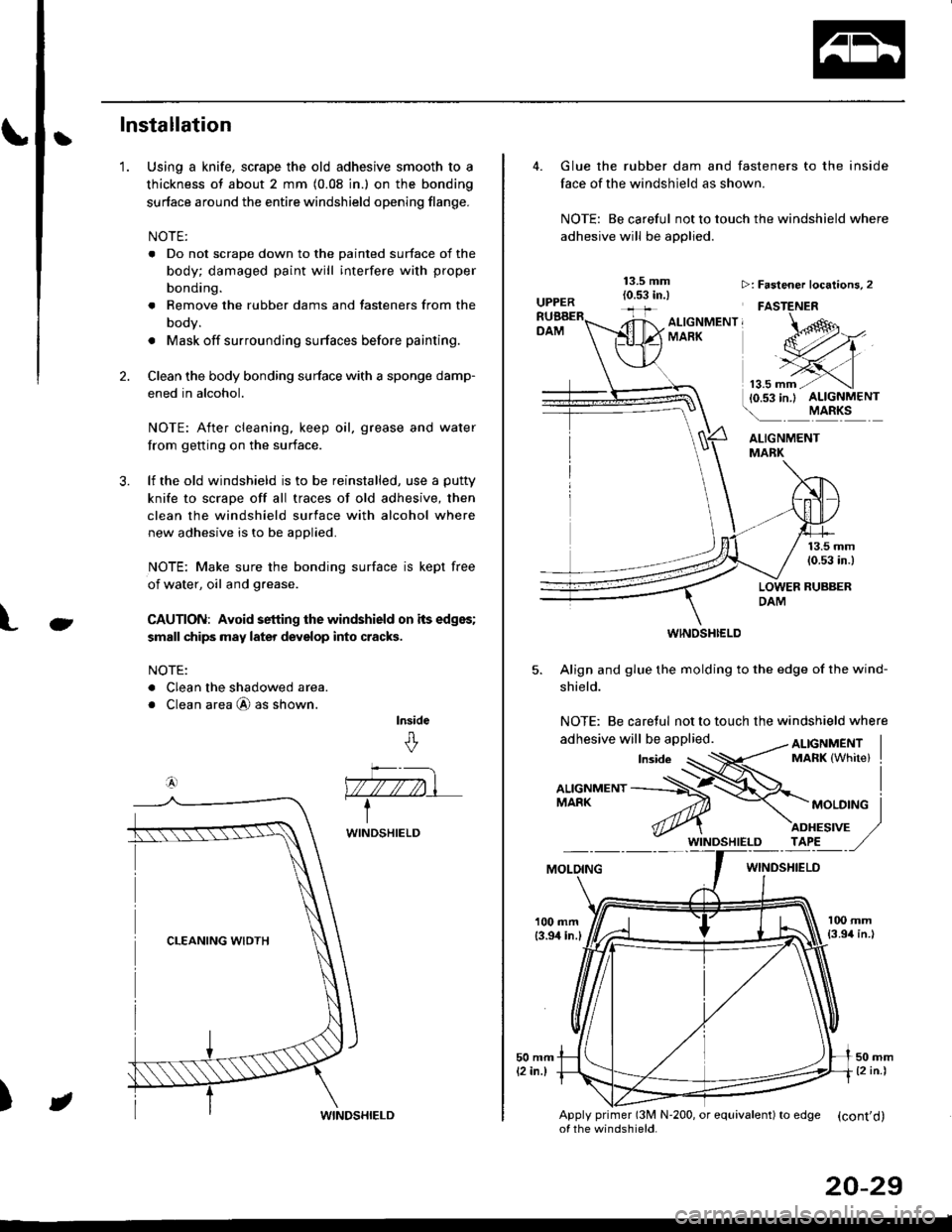
Using a knife, scrape the old adhesive smooth to a
thickness of about 2 mm (0.08 in.) on the bonding
surface around the entire windshield opening flange.
NOTE:
. Do not scrape down to the painted surface of the
body; damaged paint will interfere with proper
bonding.
. Remove the rubber dams and tasteners from the
body.
. Mask off surrounding surfaces before painting.
Clean the body bonding surface with a sponge damp-
ened in alcohol.
NOTE: After cleaning, keep oil, grease and water
from getting on the surface.
lf the old windshield is to be reinstalled, use a putty
knife to scrape off all traces of old adhesive, then
clean the windshield surface with alcohol where
new adhesive is to be applied.
NOTE: Make sure the bonding surface is kept free
of water, oil and grease.
CAUTION: Avoid setting the windshield on its edges;
small chips may later deyelop into cracks.
NOTE:
. Clean the shadowed area.
o Clean area @ as shown.
lnside
&
'1.
2.
3.
Ct
a4)
)
WINDSHIELD
JWINDSHIELD
20-29
Glue the rubber dam and fasteners to the inside
face of the windshield as shown.
NOTE: Be careful not to touch the windshield where
adhesive will be applied.
ALIGNMENTMABK
13.5 mm(0.53 in.)
LOWER RUBBERDAM
WINOSHI€LD
5. Align and glue the molding to the edge of the wind-
shield.
NOTE: Be caretul not to touch the windshield where
>: Faslener localions, 2
FASTENER
ALTGNMENT, -oMARK
MOLOINGWINDSHIELO
100 mm{3.94 in.l
Apply primer (3M N'200, or equivalent) to edSe (cont'd)of the windshield.
Page 1272 of 2189
Quarter Glass
Installation (cont'd)
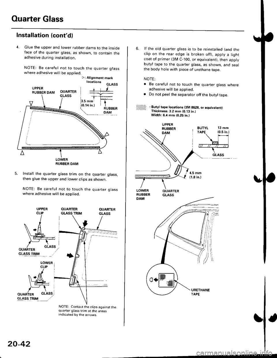
4. Glue the upper and lower rubber dams to the insideIace of the quaner glass, as shown, to contain theadhesive during installation.
NOTE: Be careful not to touch the quarter glasswhere adhesive will be applied.>: Alignment marklocationsGLASSUPPERRUBBER DAM
LOWERRUBEER DAM
Install the quarter glass trim on the quarter glass,then glue the upper and lower clips as shown.
NOTE: Be careful not to touch the quarter glasswhere adhesive will be applied.
OUARTERGLASS TRIMOUARTERGLASS
GLASS TRIM
NOTE: Contact the cljps against thequarter glass trim at the areasIndicated by the arrows.
UPPER
20-42
6. lf the old quarter glass is to be reinstalled (and theclip on the rear edge is broken off), apply a lightcoat of primer (3I/ C-100, or equivalent), then applybutyl tape to the quarter glass, as shown. and sealthe body hole with piece of urethane tape.
NOTE:
. Be careful not to touch the quaner glass whereadhesive will be applied,. Do not peel the separator offthe butyltape.
//////// '. 8u'Jt tape tocarions t3M 8628, or equivetenrl' Thickness:3.2 mm lo.t3 in.lWidth: 6.4 mm {0.25 in.)
BUTYL 13 mmTAPE (0.5 in.l
\\l
,7r--/r4--;*--T-
.. GLASS
UPPERRUEBERDAM
Page 1323 of 2189
Exterior
Component Location Index
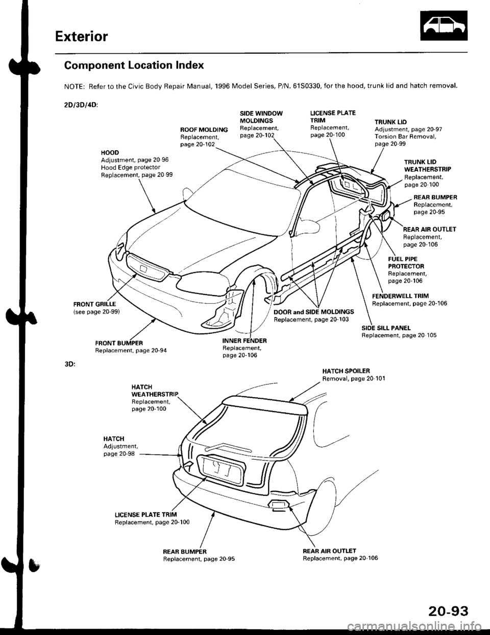
NOTE: Refer to the Civic BodV Repair Manual, '1996 Model Series, P/N.6150330,forthe hood, trunk lid and hatch removal.
2Dl30llDl
LICENSE PLATETRIM TRUNK LIDROOF MOLOINGReplacement,
SIDE WINDOWMOLDINGSReplacement,page 20-102Replacement,page 20-100Adjustment, page 20-97Tolsion Bar Removal,page 20-10220 99
HOODAdiustment, page 20 96Hood Edge protector
Replacement, page 20 99
TRUNK LIDWEATHERSTRIPReplacement,page 20-100
REAR BUMPERReplacement,page 2O-95
SILL PANELReplacement, page 20 105
REAR AIR OUTLETReplacement,page 20-106
FUEL PIPEPROTEfiORReplacement,page 20-106
FENDERWELL TRIMReplacement, page 20-106
Replacement,page 20-106
3D:
HATCH
HATCHAdjustment,page 20-98
WEATHERSTRIP
20-93
Page 1330 of 2189
Trunk Lid/Hatch
WeatherstripLicense Plate Trim
Replacement
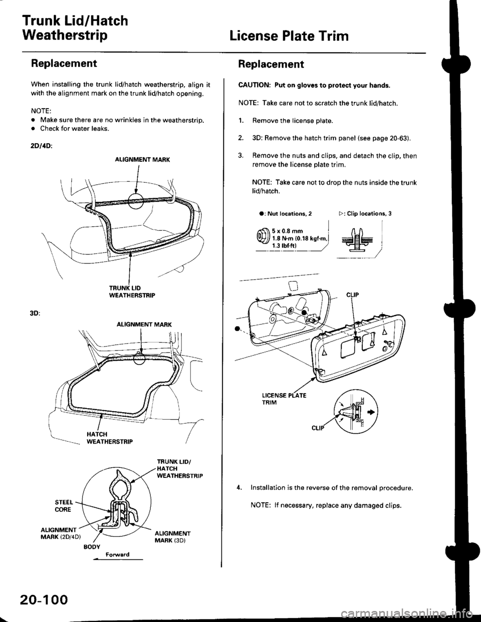
When installing the trunk lid/hatch weatherstrip. align it
with the alignment mark on the trunk lid/hatch opening.
NOTE:
. Make sure there are no wrinkles in the weatherstrip.
. Check for water leaks.
2DllDi
STEEI.CORE
3D:
ALIGNMENTMARK (2Dl4D)
ALIGNMENT MARK
WEATHERSTRIP
ALIGNMENT MARK
BODY
\
20-100
Replacement
CAUTION: Put on glov€s to plotest your hands.
NOTE: Take care not to scratch the trunk lid/hatch.
1. Remove the license plate.
2, 3D: Remove the hatch trim panel (see page 20-63).
3. Remove the nuts and clips, and detach the clip, then
remove the license plate trim.
NOTE: Take care not to drop the nuts inside the trunk
lid/hatch.
a: Nut locations,2
6fi\5x0.8mm Irvr?// 1,8 N.m {0.18 kst.m,l- j llrftl ,/
>: Clip locations,
InA
aa# )
-,/
Installation is the reverse of the removal orocedure.
NOTE: lf necessary, replace any damaged clips.