sensor HONDA CIVIC 2000 6.G Workshop Manual
[x] Cancel search | Manufacturer: HONDA, Model Year: 2000, Model line: CIVIC, Model: HONDA CIVIC 2000 6.GPages: 2189, PDF Size: 69.39 MB
Page 1211 of 2189
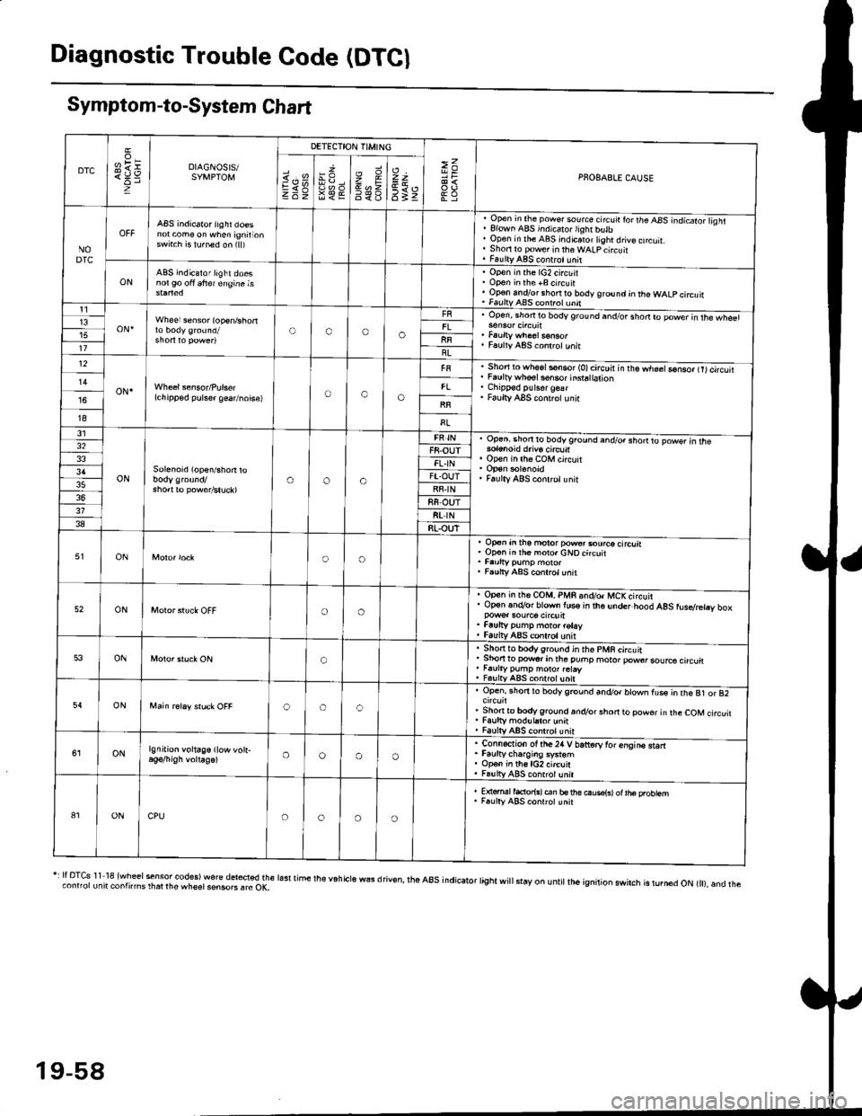
Diagnostic Trouble Code (DTCI
Symptom-to-System Chart
DTC
oH1=DIAGNOSIS/SYMPTOM
DETECTION TIMING
>=PNOBABLE CAUSEi.'sEV98€E
zr\9=6<_6
=t
6tz
NODTC
ABS indicator iighr doesnot com€ on when ignirionswrt.h is lu.ned on (ll)
, Open in the pow€. source circ!ir ror the ABS -.ndicato;l isht. Elown ABS indicalo.lighr butb' Open in rhe ABS indicaror tight drive cncuit.. Shori ro pow€r in theWALpcircuit. FaultyABS contrct!nit
ONABS indicator light doesnol90 oft 6frer engine isOpen in the lG2 circuitOpon in the +B circuirOp€n andlor short ro body ground jn the WALP circuitFaultv AAS coni.ol unnt1
oN.Wheel sensor (op€n/shortOooo13upen, snofiro bodyground and/or shodro power in rhe wh€61
Faulty ABS co.lrctunitllBL12
oN.(chipp€d pulser gea/noise)oao
Short to wh6sls€n6or (O)circuir in t'e.h;;Go-nso, trtcircutiFaulty whsel s€nsor insra|ation
Faulty ABS cont.olunir
I8
31
ONSolenoid (open/shon roaoa
Op.ni shon to bodyground and/o. shorrto powsr in rhe
op€n in lh6 coM circuit
Faulty ABS conlrclunit
32F8-OUTFL.IN3'lFT.OUTRF.IN88 OUT318t rN38RLOUT
ONoo
op€n in tho motor pow€..ourco circliaOp€n inih€ moro.cNOcircuit
Faulty ABS conrrol unit
52ONoo
Open in rh€ COM, PMR 6nd/o. MCKcircuirOp€n.n.Vor blown lus€ in the under hood AgS rusdretry box
Faufty pump moto. rotayfaulv ABS conlrolunit
53ONo
. Sho.tto bodygrou.d in the pMR circuit. Shon to powsr in tha puhp moror pow6rsource circu. r.urty pump motor.etay, FalltyABS contolunit
54ONooc
Open, rhorr ro bodygrcund and/or blown fus€ in the B1 or 82
Shonto body ground.n.Vor short to powor in rhe COM circuitFaulty modul.tor unnFaulty ABS controt unit
ONlgnition voltage (low vott-oooo
. Connection ot the24 V bariorv tor enqins starr. Faurtycharoins system. Op€n in th6lG2 circuit. Fa!lly ABS contrcl unil
81ONCPUoooo
E {€rml facior{sl en bs rhe ouse{sl ot |he probtemF.ulty ABS conrrot unit
r: It DTcs 1 1 18 {wheel sensor codes) wore del*ted the lasr time the v6h cls wEs d riv€n, rhe a8s indicator tight wi
stay on u ntit lh6 ignition swirch is rurn6d oN t), and theconnorunit contnms rhat rhe wheet sensoB . rc OK,
19-58
Page 1212 of 2189
Le
\.t
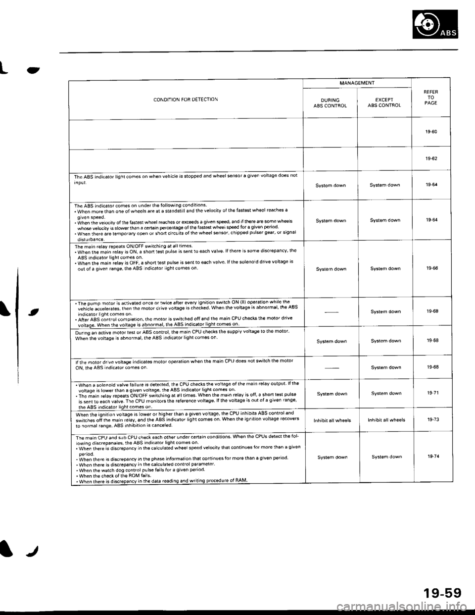
CONDITION FOR DETECTION
MANAGEI\,4ENT
FEFERTOPAGEDUNINGABS CONTFOLEXCEPTABS CONTAOL
19-60
19-62
The ABS indicator lighl cones on when vehicle is stopp€d and wheel sensor a given vohaqe does nol
19 64
The ABS indicaror comes on under th€lollowing conditions.When morethan one otwheels are a standstiland thelelocirv otthe fastest wheel reaches a
' fohen th. velocity of the faslesl wheel reaches or exceds a given sped, and it there ar€ somewh@lswhose velocity is slowe.lhan a cenain percenlage oi lh€ fast6t wheelsped for 3 given period. when rhere are lemporary open or short ctcuits ol rhe wheel sonsor' chipp€d pulser gear, orsrgnalorslJrbaaLe
19 64
The main relay repeats ON/OFF switching atalltimes.WhenthemainrelayisON,ashortt$tpulseissentloeachvalve lfthere s some dis'repa ncv, lheABS indicalor lightcomes on.. When rhe main relay is OFF, a shonl€sl pulse is s€nlto each valve lfth6 solenoid drive voltage rsout ol a qiven range, the ABS ndicalor lighl comes on19-66
'The pump nolot s activaled orc€ o' Mrce sfier every gn't'on sw'lch ON (ll) operarion whrle lte -^vchicle acLelerales lrenthemolorotivevo'taSersrhecled When lhevolla96 rs abnormar,lre Absindicaror llghl comes on.. Afte. ABS ;onl rol com pletion, the moror isswitched ofi 6nd the main CPU checks the molor dnvevoltase. when rhe vortase is abnormsl, the ABS indicato49!!!99!:l!:_-
19-68
D!rino an active motor lesl or AAS control,lhe main CPU checks ihe supplv voltage to the motor'whe;lhe vohage s abnofmal, the ABS indicator lightcomes on19,68
lirhe moror drvevoltage indicates molot operalion when the main cPU does notswilch the motoroN, rhe ABs indicaro. comes on19-64
. Wh"" " ".1"".1d ""1r. f"llure is detecred, the CPU checksth€ voltage ofthe main rel6v output lllhevohaqe is lowerthan 6 given vohage, theABS indicator light comes on. The ;ain r€lay repeats ON/OFF switching ar a!ltimss when the main rel.v is ofi, a shorl l6st pulse
is sent ro €ach valve. The CPU mon tors the reJer€nce vohage ll the vohage is out ot a g iven range'
the ABS indic.tor lightcomes on
19 71
wt'",, rt'e lgnitlon rottag" is ower or higherthan a given voltage,lhe CPU inhibils ABSlonlrolandswirches oli the ma in relaY, 6nd the ABS indicaror lig ht com€s on When the ig n ilion vohage recove'sto normal f6ng6, ABS inhibition is canceled.19.73
rimln CpU anO suU CeU ch€ck each other undercertain condnions. Whon rhe CPUS dstectthe fol'lowing discrepanaies, rhe ABS indicator light comss on. whe; rh€re is discGpancv n lhacarculated wheelspeed velocirv thar continuosJor more than a given
.i^/hen rhere is discrcoancv in the ehase informalion lhat continuesfor morerhan a given period' When rhere is discrepancY in thecalculared conlfol pa.amerer'. When thewatch dog conrrolp!lsetailslof a given penod. When th6 checkotth€ ROM tai1s.. when there is disrepancy inrhe data roading.nd wriung prcledurc ot RAM
19 7'l
tr
19-59
Page 1217 of 2189
Troubleshooting
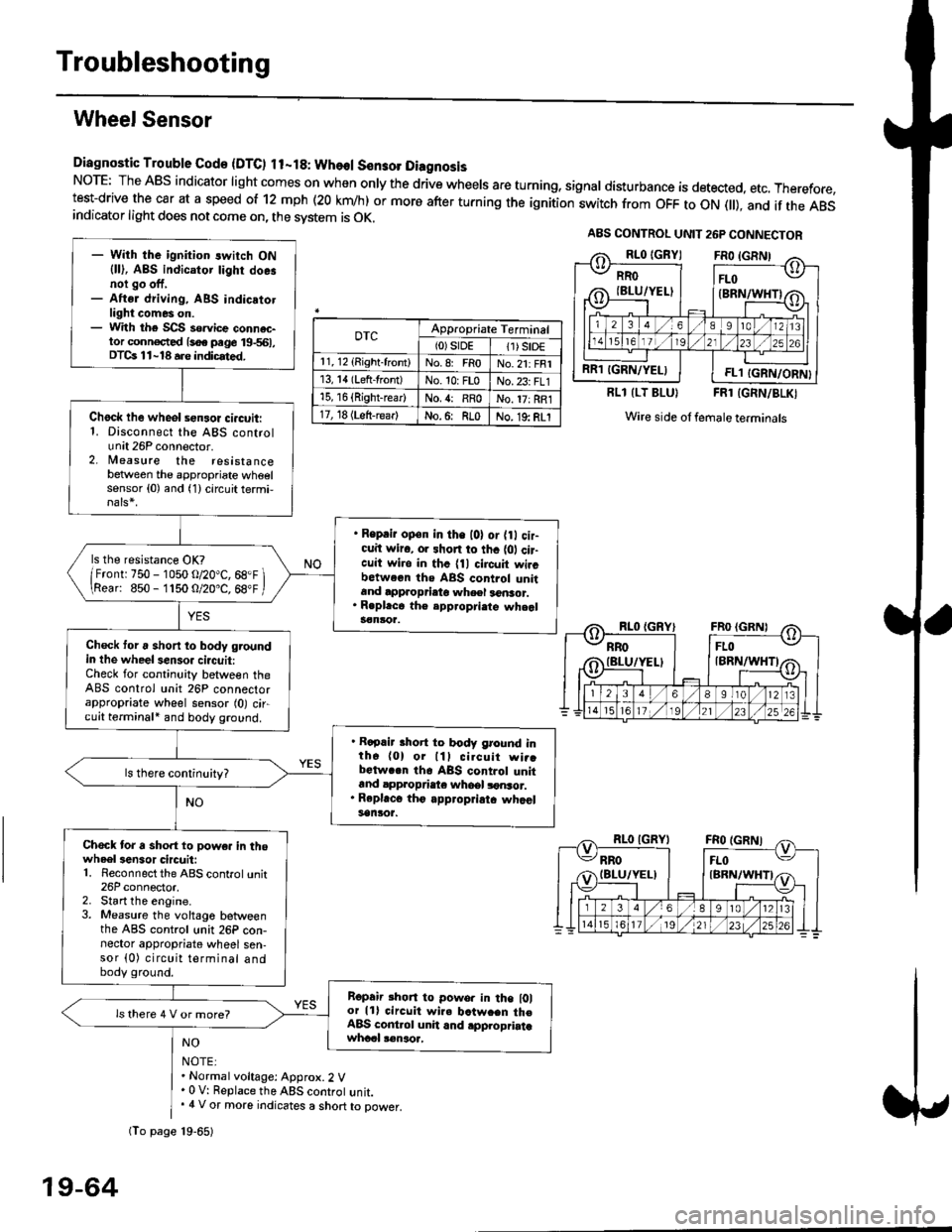
Wheel Sensor
Diagnostic Trouble Gode {DTC) ll-18: Wheol S€n3ol DiagnosisNoTE: The ABS indicator light comes on when only the drive wheels are turning, signal disturbance is detected, etc. Therefore,test-drive the car at a speed of 12 mph (20 krn/h) or more after turning the ignition:witch from OFF to ON fll), and if the ABSindicator light does not come on, the svstem is OK.
0TcAppropriate Terminal(0)srDE11) SrD€r 1, 12 (Right-front)No.8: FRoNo.21: FRI13, 14 (Left-front)No. 10: FLoNo.23: FL115, 16 {Right-rear)No. {: RRoNo. 17: RRl17, 18 (Left-rear)No.6: RLoNo. 19: RLI
RLl (LT BLU}FRl (GRN/BLKI
Wire side ol female terminals
NO
NOTE:. Normal voltage: Approx.2 V' 0 V: Replace the ABS controt unit.. 4 V or more indicates a short to power.
A8S CONTROL UNIT 26P CONNECTOR
RRO
IBLU/YELI
RR1 IGRN/YELIFL1 IGRN/ORN}
- With the ignition switch ON{ll), ABS indicator tighr doe.noi go off,- Aftsr driving, ABS indicatotlight comes on.- With the SCS so.vice connac-tor conn€c,ted {soe pege 19-561,DTCs 11-18 a.e indicrted.
Chock lhe wheol sensor ci.cuit:1. Disconnect the ABS controlunit 26P connector.2. lleasure the resistancebetween the appropriate wheelsensor (0) and (1) circuit termi,
. Reprir op€n in the l0l or {0 cir-cuit wiro, or shon to thc {01 cir-cuit wi.o in thc {11 circuit wircbctween ths ABS control unitand approprieto wheel a6nsor.. R.pl.ce th€ epp.opri.te wheal3€nloa.
ls the resistance OK?
/Frontr 750 - 1050 o/20"C, 68.F \\Rear: 850- 1150 O/20.C, 68"F /
Check toru short to body groundin the wheel senso. circuit:Check for continuity between theABS control unit 26P connectorappropriate wheel sensor (0) circuit terminali and body ground.
. Rapair short to body ground inth6 (0) or lll cilcuit wi..bctwa.n th6 ABS control unitand appropdaie whoel lonsor.. Rep|'c6 tho appropriatc whcelsanlor.
Chock tor a sho.t to powe. in thowheel3en3or circuit:1. Reconnect the ABS control unit26P connector,2. Start the engine.3. Measure the voltage betweenthe ABS control unit 26P con-nector appropriate wheel sen-sor (0) circuit terminal andbody ground.
Ropair rhon to powo. in the l0lor lll circuit wire batw.en th€ABS cont.ol unit and .pplopriatawhccl !€naoa,
ls there 4 V or more?
fio page 19-65)
19-64
Page 1229 of 2189
ABS Control Unit
Pulsers/Wheel
Sensors
Replacement
1. Remove the right side kick panel.
2. Disconnect the ABS control unit connecrors.
3. Remove the ABS control unit,
4. lnstall the ABS control unit in the reverse order of
removal,
CONNECTORS
19-76
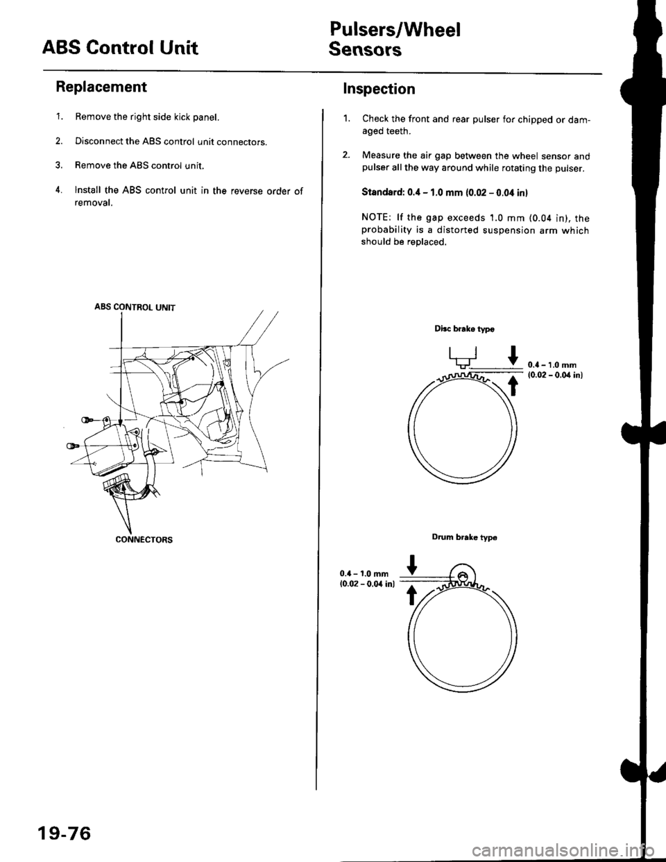
Inspection
Check the front and rear pulser for chipped or dam-aged teeth.
Measure the air gap between the wheel sensor andpulser all the way around while rotating the pulser.
Slandard: 0.4 - 1.0 mm (0.02 - 0.04 in,
NOTE; lf the gap exceeds 1.0 mm (0.04 in), theprobability is a distorted suspension arm which
should be replaced.
Dbc brake typo
0.{ - 1.0 mm(0.02 - 0.04 in)
Drum brake typ6
1.
Page 1230 of 2189
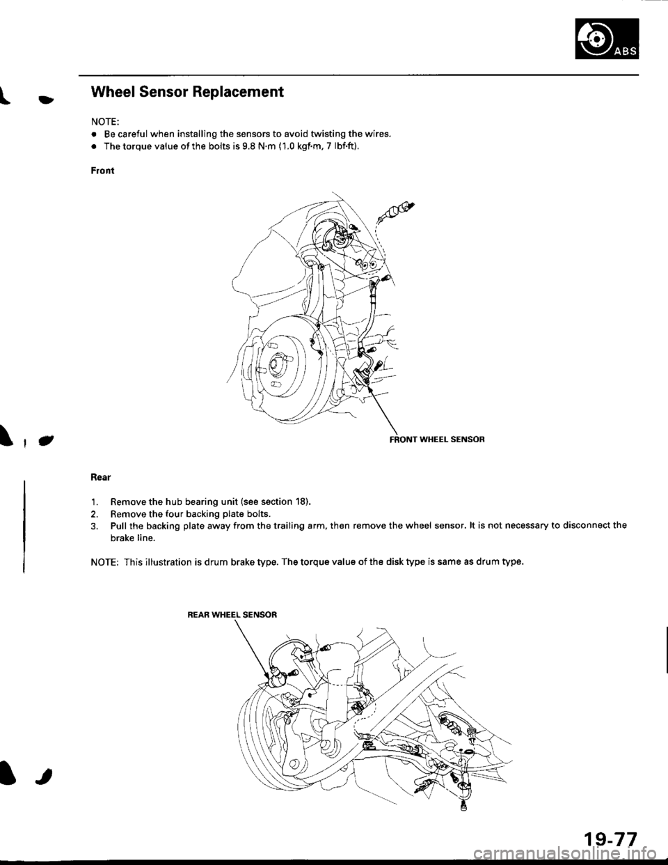
l}tWheel Sensor Replacement
NOTE:
. Becareful when installingthe sensors to avoid twisting the wires.
. The torque value of the bolts is 9.8 N.m (1.0 kgf.m, 7 lbf.ft).
Front
FRONT WHEEL SENSOR
Rear
1. Remove the hub bearing unit (see section 18).
2. Remove the four backing plate bolts.
3, Pull the backing plate away from the trailing arm, then remove the wheel sensor. lt is not necessary to disconnect the
brake line.
NOTE: This illustration is drum brake type. The torque value of the disk type is same as drum type.
REAR WHEEL SENSOR
J\
It
19-77
Page 1453 of 2189
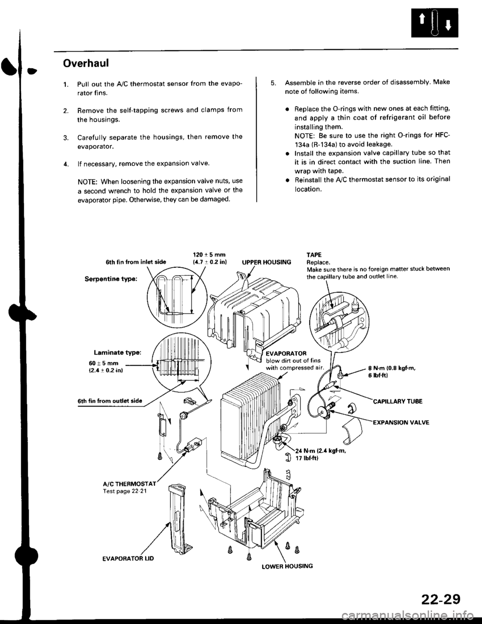
Overhaul
1.
3.
Pull out the A,/C thermostat sensor from the evapo-
rator fins.
Remove the self-tapping screws and clamps from
the housings.
Carefully separate the housings, then remove the
evaporator.
lf necessary, remove the expansion valve.
NOTE: When loosening the expansion valve nuts, use
a second wrench to hold the expansion valve or the
evaporator pipe. Otherwise, they can be damaged
5. Assemble in the reverse order of disassembly Make
note of following items.
. Replace the O-rings with new ones at each fitting,
and apply a thin coat of refrigerant oil before
installing them.
NOTE: Be sure to use the right O-rings for HFC-
134a (R-134a) to avoid leakage.
. Install the expansion valve capillary tube so that
it is in direct contact with the suction line. Then
wrap wath taPe.
. Reinstall the Ay'C thermostat sensor to its original
location.
6th tin lrom inld side
Serpentine type:
Laminate typo:
TAPEReplace.lvake sure there is no foreign matter stuck between
60t5mml'2.1! O.2 inl
EVAPORATORblow din out of linswith compressed air,
HOUSING
8 N.m 10.8 kgt m,6 tbf.ftl
6th fin lrom outle't sideCAPILLARY TUAE
VALVEN
u'
ll
6\N.m (2.it kgt.m,17 tbtftl1l
A/C THERMOSTfesr page 22 21
%
EVAPORA
LOWER
22-29
Page 1471 of 2189

l'f .
Electrical
Special Toofs .,....................,23-2
Troubleshooting
Tips and Precautions ..............,.................... . 23-3
Five-step Troubleshooting .............. ......... . . 23-5
wire color codes ..........,23-5
Schematic Symbols ........,................... . . .. .... 23-6
Relay and Control Unit Locations
Engine Compartment ...,..................... ... .. . 23'7
Dashboard ......................23-8
Dashboard/Door ......... 23-12*Airbags ................. ....... Section 24
Air Conditioning ......... Section 21
Aftelnator ..........."""" """ 23-112
Anti-lock Brake System {ABS) Section 19*A/T Gear Position Indicator .....................,. .... ... 23-149
Automatic Transmission Svstem .... . ....... Section 14
Batterv ......... . . . ... ...... .......23-91
Blower controls .. . ... Section 2l
Charging System ....'...........23'112
Connector ldentilication and Wire Harness
Routing .................. ......23'13
Cruise Control ............,........23-240
Dash Lights Brightness Controller ............. ....... 23-180
Fan controfs "" 23'126
Fuel PumD ........ . ........ section 11
Fuses/Refay ...............,..,,.. 23'62
PGM-FI Control System ......................,....... Section 1 1
*Gauges
Circuit Diagram ....,.,.......23-131
Fuef Gauge ...........'.'.......23-142
Gauge/lndicator .. . .. 23-129
Ground Distribution .. . 23-75
Heatei controls .. . ..... Section 21*Horn................. ...............23-196
*tgnition Switch ....................23-89
lgnition System .......,.... 23-102
*lntegrated Control Unit ....................................... 23-156
fnterlock System ,........ . . , ,23-144
Lighting System . . . .. ......... 23-161
Lights, Exterior
Back-up Lights ..'............23'171
Brake Lights .................. 23'174
Daytime Bunning Lights (Canadal ............... 23'166
Front Parking Lights ......,................ .'. .......... 23-167
Front Turn Signal Lights .......... . . ............ ..,.23-167
Headtights ....".'....-... ..... 23'167
High Mount Brake Light ...................... ... .23'179
License Plate Lights ...... 23'176
Taitfights ................ .......23'171
lnterior Lights ..-.......,, . 23-142
Moonroof ..,.................,........ 23-235
Power Distribution ....... . . .23-61
Power Door Locks .......,,,. .23'251
Power Mirrors ,..............,.,...23'206
Power Relays ....... . ...... . . .. 23-86
Power Windows ............,,....23-220
Rear Window Defogger .......................... . . ... . . 23-2OO
Spark Plugs . ..... . ........ .....23-111
Slarting System ................23-93*stereo Sound Svstem ,................. ..... ... . ... ,.,.,,23'147'Supplemental Restraint System (SRS) ... . Section 24
Turn Signal/Hazard Flasher System .......'.'....-... 23-173
*Undel-dash Fuse/Relay Box ............,.................. 23-85
vehicfe soeed sensor (VSSI """" ""' 23-140+Wipers/Washers .........,.,.,...23-214
NOTE: Unless otherwise specified, references to auto-
matic transmission (Mf) in this section include the CVT.
Page 1483 of 2189
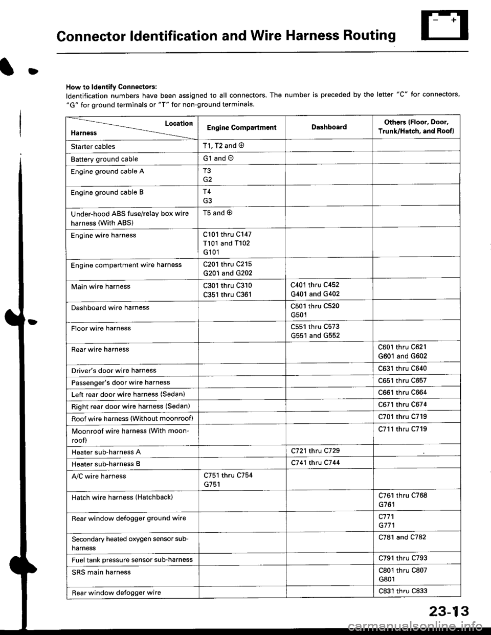
Connector ldentification and Wire Harness Routing
D
How to ldentify Connectors:
ldentification numbers have been assigned to all connectors. The number is preceded by the letter "C" for connectors,"G" for ground terminals or "T" for non-ground terminals.
Location
HarnessEngine CompartmentDashboardOthers {Floor, Door,
Trunk/Hatch, and Rootl
Starter cablesT1, T2 and @
Battery ground cableG1 and O
Engine ground cable AT3
G2
Engine ground cable BT4
Under-hood ABS fuse/relay box wire
harness (With ABS)
t5 ano (9
Engine wire harnessCl01 thru C147
T101 and T102
G101
Engine compartmenl ware harnessC201 thru C215
G201 and G202
Main wire harnessC301 thru C310
C351 thru C361
C401 thru C452
G401 and G402
Dashboard wire harnessC501 thru C520
G501
FIoor wire harnessC551 thru C573
G551 and G552
Rear wire harnessC601 thru C62l
G601 and G602
Driver's door wire harnessC631 thru C640
Passenger's door wire harnessC651 thru C657
Left rear door wire harness (Sedan)C661 thru C664
Right rear door wire harness (Sedan)C671 thru C674
Roof wire harness (Without moonroof)C701 thru C719
Moonroof wire harness {With moon-
roof)
C7l'l thru C719
Heater sub-harness AC721 thru C729
Heater sub-harness BC7 41 thtu C7 44
Ay'C wire harnessC751 thru C754
G751
Hatch wire harness (Hatchback)C761 thru C768
Rear window defogger grgund wirec771
G171
Secondary heated orygen sensor sub-
narness
C781 and C782
Fuel tank pressure sensor sub-harnessC791 thru C793
SRS main harnessC801 thru C807
G801
Rear window defogger wireC831 thru C833
Page 1486 of 2189

Connector ldentification and Wire Harness Routing
Engine Wire Harness lD16Y5, D16Y8 enginss): '96 - 98 models
Connector or
Torminal
Numbsr of
CavitissLocationConnects toNot€s
c 101c102c103c104c104c105c106c107c108c 109c110c111c112c113c114c115c116cl17c118c119c120cl21
c122c123cl23c124
c125
c127c12Ac129c130c131c132c 133c134c135
c136
c138c139c140c 141c142c 143c144cl44c145c'146cl47
10
1
22
14l4322l0I
2
2
2
2120
3l
14
14
1222
2
2
22
Left side of engine compartmentMiddle of engineMiddle of engineLeft side of engine companmentLeft side of engine compartmentMiddle of engineMiddle of engineMiddle of engineMiddle of engineMiddle of enginefvliddle of engineMiddle of engineMiddle of engineMiddle of engineMiddle of engineMiddle of engineMiddle of engineLeft side of engine compartmentMiddle of engineMiddle of engineMiddle of engineMiddle of engine
Middle of engineMiddle of engineMiddle of engineMiddle of engineMiddle of engineMiddle of engineMiddle of engineMiddle of engineMiddle of engineRight side of engine companmentBehind right kick panelUnder right side of dashUnder riOht side of dashUnder right side of dashUnder right side of dashUnder right side of dashUnder right side of dash
Under right side of dash
Under right side of dash
Middle of engineMiddle ot enginel iddle of engineMiddle of engineMiddle of ongineMiddle of engineLeft side of engine compartmentMiddle of engineMiddle of engineRight side of engine compartmentRight side of engine compartmentRight side of engine compartment
USACanada
Afi
USA
-' (A/r)
Main wire harness (C303)Crankshaft speed fluctuation (CKF) sensorEngine oil pressure switchAlternatorAlternatorNo. 'l fuel injectorNo. 2 fuel injectorNo.3 fuel injectorNo. 4 fuel injectorIAC valveThrottle position (TP) sensorl\4anifold absolute pressure (MAP) sensorIntake air temperature (lAT) sensorPower steering pressure {PSPI switchEVAP purge control solenoid valveJunction connectorJunction conn€ctorVehicle speed sensor {VSS}Countershaft speed sensorEngine coolant temp€rature (ECT) switch ADistributorEngine coolant temperature (ECT) sendingunrtEngine coolant temperature (ECT) sensorPrimary HO2S (sensor'l)Primary HO2S (sensor 1)Back-up light switchLock-up control solenoid valveSecondary HO2S (sensor 2)Mainshaft speed sensorLinear solgnoid valveShift control solsnoid valveStarter solenoidJunction connectorMain wire harnesE (C446)ECM/PCMPCMECMiPCMECM/PCMMain wire harness (C305)
Main wire harness (C305)
Main wire harness (C305)
Knock sensor (KS)IAC valveVTEC solenoid valveVTEC pressure switchEVAP control canister vent shut valveEGR control solenoid valveSecondary gear shaft speed sensorEGR valveEGR valveDrive pulley speed sensorSolenoid connector {CVT)Driven pulley speed sensor
*, (M/T)M/T*" INT\
*, tAtf)
NT:'96 model*,(A,/T):'97 - 98mooets
moqets
M/T
-1 (l,/T)*, (A,/T)-,(4,/T)*1 {M/T)*, (A,/T)*1 (CW)*, (A,T)
T101r102Left side of engine companmentRight side of engine companmentAlternatorUnder-hood fuse/relay boxG 101Middle of engineEngine ground, via engine wire harness
2
*1: Dl6Y5 engine*2: D16Y8 engine*3: D16Y5 (Ay'T), D16Y8 engines
3-16
Page 1488 of 2189
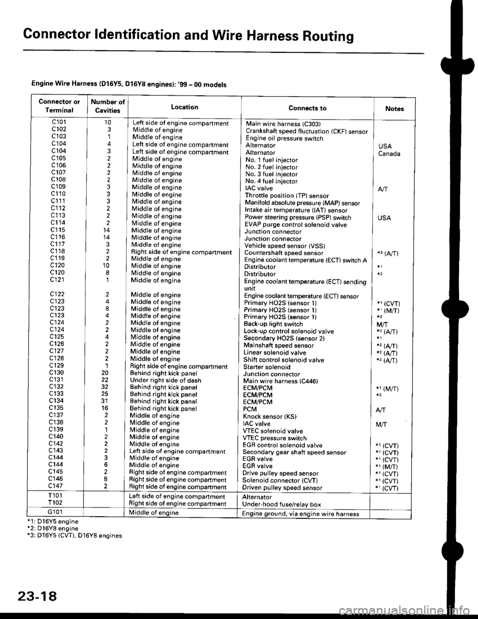
Gonnector ldentification and Wire Harness Routing
Engine Wire Harness (D16Y5, Dl6Yg engines): ,99 - 00 models
Connectot or
Terminal
Number ot
CavitiesLocationConn€cts toNotes
c'101cl02c103c104c 104c10s
c107c 108c'r09c110c111cl12c113cl14c l15c116cl17c118c119c120cl20c121
c122c123c123cl23cl24c124c125
c127c12Ac129c 130c131cl32c133c 134c135c137c138c 139c 140c142c143c144cl44c145c146c147
103,]
322223332221414322'10
8,l
2484224222120
32
2212223
282
No. 1 luel injector INo.2 fuel injectorNo.3 fuel injector ]No. 4 fuel injector iIAC valve I anThrottle position lTP) sensorManifold absolute pressure {MAP) sensor IIntake air temperature (lAT) sensor IPower steering pressure (PSP)switch USAEVAP purge control solenoid valve ]
Main wire harness 1C303)Crankshaft speed fluctuation (CKF) sensorEngine oil pressure switchAlternatorAlternator
Left side ot engine compartmentlvliddle of engineMiddle of engineLeft side ot engine compartmentLeft side of engine compartmentMiddle of engineMiddle ot engineMiddle of engineMiddle of engineMiddle oI engineMiddle of engineMiddle of engineMiddle of engineMiddle of engineNliddle of engineMiddle of engineMiddle of engineMiddle of engineRight side of engine compartmentMiddle of engineMiddle of engineN4iddle of engineMiddle of engine
Middle of engineMiddle ot engineMiddle ot engineMiddlo of engineMiddle of engineMiddle ot enginelrliddle of engineMiddle of engineMiddle oI engineMiddle ot engineRight side of engine compartmenlBehind right kick panelUnder right side of dashBehind right kick panelBehind right kick panelBehind righr kick panelBehind right kick panelMiddle ot engine[,liddle of engineN4iddle of engineMiddle of engineMiddle oI engineLeft side of engine compartmentMiddle of engineMiddle of engineRight side ol engine compartmentRight side of engine companmentRight side of engine compartment
USACanada
Junction connectorJUnct|On COnnectorVehicle speed sensor lVSS)Countershaft speed sensorEngine coolant temperature {ECT} switch ADistributorDistributorEngine coolant temperature (ECT) sendingunitEngine coolant temperature (ECT) sensorPrimary H02S (sensor 1)Primary HO2S (sensor 1)Primary HO2S lsensor 1)Back-up light switchLock'!p control solenoid valveSecondary HO2S (sensor 2)Mainshaft speed sensorLinear solenoid valveShift control solenoid valveStarter solenoidJunction connectorMain wire harness (C446)ECM/PCMECM/PCMECM/PCMPCtvtKnock sensor (KS)IAC valveVTEC solenoid valveVTEC pressure switchEGR control solenoid valveSecondary gear shaft speed sensorEGR valveEGR valveDrive pulley speed sensorSolenoid connector (CVT)Driven pulley speed sensor
*'� (A/TI
*1 (CVT)*, (M/T)
Mfia (A/Tl
" (A,/T)., (4,/r)-'� {AlrJ
*1 (M/T)
tvliT
*1 (CVT)*, (cvT)*' (cw)*1 (MiT)*1 {CVT)*1 {CVT)*, (cvr)
T101T102Left side of engine companmentRight side ot engine companmentAlternatorUnder'hood fuse/relay boxG 101Middle of englne IEngine ground, via engine wire harness*1: 016Y5*2: D16Y8*3: Dl6Y5
engineengine(CW), D16Y8 engines
23-14